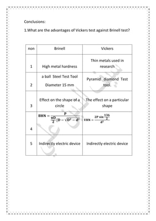
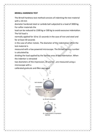
HARDNESS TESTING
Baghdad University
College of Engineering
Department of Mechanical Engineering
Name of Experiment
" HARDNESS TEST"
Preparation:
Saif al-Din Ali Madi
The second phase
Group "A "
HARDNESS TEST
1. OBJECT
The hardness test is a mechanical test for material properties
which are used in engineering
design, analysis of structures, and materials development. The
principal purpose of the
hardness test is to determine the suitability of a material for a
given application, or the
particular treatment to which the material has been subjected. The
ease with which the
hardness test can be made has made it the most common method
of inspection for metals and
alloys.
1. INTRODUCTION
Hardness is defined as the resistance of a material to permanent
deformation such as
indentation, wear, abrassion, scratch. Principally, the importance
of hardness testing has to do
with the relationship between hardness and other properties of
material. For example, both the
hardness test and the tensile test measure the resistance of a
metal to plastic flow, and results
of these tests may closely parallel each other. The hardness test
is preferred because it is
simple, easy, and relatively nondestructive.
There are many hardness tests currently in use. The neccessity
for all these different hardness
tests is due to the need for categorizing the great range of
hardness from soft rubber to hard
ceramics
THEORY
Current practice divides hardness testing into two categories:
macrohardness and
microhardness. Macrohardness refers to testing with applied loads
on the indenter of more
than 1 kg and covers, for example, the testing of tools, dies, and
sheet material in the heavier
gages. In microhardness testing, applied loads are 1 kg and
below, and material being tested is
very thin (down to 0.0125 mm, or 0.0005 in.). Applications include
extremely small parts,
thin superficially hardened parts, plated surfaces, and individual
constituents of materials.
1) Macro Hardness Testers Loads > 1 kg
 Rockwell
 Brinell
 Vickers
2) Micro Hardness Testers < 1 kg
 Knoop diamond
 Vickers diamond pyramid
BRINELL HARDNESS TEST
The Brinell hardness test method consists of indenting the test material
with a 10 mm
diameter hardened steel or carbide ball subjected to a load of 3000 kg.
For softer materials the
load can be reduced to 1500 kg or 500 kg to avoid excessive indenta on.
The full load is
normally applied for 10 to 15 seconds in the case of iron and steel and
for at least 30 seconds
in the case of other metals. The diameter of the indentation left in the
test material is
measured with a low powered microscope. The Brinell harness number
is calculated by
dividing the load applied by the surface area of the indentation. When
the indentor is retracted
two diameters of the impression, d1 and d2 , are measured using a
microscope with a
calibrated graticule and then averaged
=
2
[ − √ −
Where:
P ; is the test load [ kg]
D ;is the diameter of the ball [mm]
d ; is the average impression diameter of indentation [mm]
The diameter of the impression is the average of two readings at right
angles and the use of a
Brinell hardness number table can simplify the determination of the
Brinell hardness. A well
structured Brinell hardness number reveals the test conditions, and
looks like this, "75 HB
10/500/30" which means that a Brinell Hardness of 75 was obtained
using a 10mm diameter
hardened steel with a 500 kilogram load applied for a period of 30
seconds. On tests of
VICKERS HARDNESS TEST
The Vickers hardness test method consists of indenting the test
material with a diamond
indenter, in the form of a right pyramid with a square base and an
angle of 136 degrees
between opposite faces subjected to a load of 1 to 100 kgf. The
full load is normally applied
for 10 to 15 seconds. The two diagonals of the indentation left in
the surface of the material
after removal of the load are measured using a microscope and
their average calculated. The
area of the sloping surface of the indentation is calculated. The
Vickers hardness is the
quotient obtained by dividing the kgf load by the square mm area
of indentation.
When the mean diagonal of the indentation has been determined
the Vickers hardness may be calculated from the formula, but is
more convenient to use conversion tables. The Vickers hardness
should be reported like 800 HV/10, which means a Vickers
hardness of 800, was obtained using a 10 kgf force. Several
different loading settings give practically identical
hardness numbers on uniform material, which is much better than
the arbitrary changing of
ROCKWELL HARDNESS TEST
The penetrators for the Rockwell hardness tester range from 1/2-inch
diameter steel balls very small diamond (brale) tips (points). The smaller
points are used for to harder materials that have a greater resistance to
indentation. There are various force scales used for various materials.
The Rockwell B and Rockwell C scales will be used for this experiment.
The Rockwell B scale is suitable for soft engineering metals, and the
Rockwell c scale is appropriate for hard engineering metals. Each scale
requires a specified p and load. The B scale uses a 1 / 16- inch diameter
steel steel ball and a 100- kg load. The c scale uses a conical diamond
point and a 150-kg load.
To perform the Rockwell tests, the penetrator is pressed against
the specimen with an ini al 10-kg preload to properly seat the
penetrator. The remaining load is applied gradually after the dial on the
hardness tester has been zeroed After the penetrator has stopped
moving into the specimen, the final position of the dial pointer indicates
the Rockwell hardness number that is related to the depth of
penetration.
There are numerous scales in Rockwell test, which are made possible by the
combination of different loads and indenters .The ranges are identified by letters
and the common scales range from A through K, with I and J left out, as given in
the following table
scale indenter
Minor
Load kg
Minor
Load kg
totel
Load kg
Scale
color
A
DINMOND CONE 10
50 60
BlackC 140 150
D 90 100
F
1/6 in steel ball 10
50 60
redB 90 100
G 140 150
H
1/8 in steel ball 10
50 60
E 90 100
red
K 140 150
materials to be tested different materials specimens will be tested in
this laboratory experiment namely: aluminum alloy, carbon steel,
stainless steel, al-alloy, commercial pure copper and
brass. The hardness of mild-steel washer will also be tested to check the
validity of Brinell hardness test.
EQUIPMENT TO BE USED
Universal hardness tester up to 187.5 kg
STUDENT WORK
perform Brinell and Rockwell hardness test, Selected students will be
invited to instructor will do perform Vickers test in order to avoid the
diamond pyramid damage that could be taken place.
For Brinell experiment, student has to calculate the BHN and depth
of impression (h) through the following formulas for each material
tested:
=
[ − √ −
For Vickers experiment, student has to calculate the VHN through the
following formula for each material tested:
=
	
For Rockwell experiment, student has to calculate the depth due to
major load through the following formulas for each material tested:
	 	 = −
.
( 	 	 	 	 )	
	 	 = −
.
(RHB OR RHE OR RHF OR RHG
ORRHH OR RHK)
Table and test results
High hardness testing
B.H.N
D=10 mm
non
d
mm
P
kg
B.H.N
1 3 3000 415
2 3 1000 138
3 3 500 69.1
4 5 3000 143
5 5 1000 47.6
6 5 500 23.8
Result of theoretical;
1. =
[
=
2. =
[
= .
3. =
[
= .
4. =
[
= .
5. =
[
= .
6. =
[
= .
Table of Rockwell Processes for
Ferrous Metals
Table Rockwell Practical
Test Non - ferrous Metals
NON Pregnancy R.H.N
ferrous
Metals
R.H.N
1
100-150 kg
56
cu
71
2 58 73
3 58 73
4 69 73
5 57 73
6 57
AL
71
7 57 67
8 56 70
9 57 70
10 58 64
Result of theoretical;
AL
Avr= = 68.5
Cu
Avr= = 72.6
Steel
Avr= = 58.3
Conclusions:
1.What are the advantages of Vickers test against Brinell test?
non Brinell Vickers
1 High metal hardness
Thin metals used in
research
2
a ball Steel Test Tool
Diameter 15 mm
Pyramid diamond Test
tool.
3
Effect on the shape of a
circle
The effect on a particular
shape
4
=
[ − √ − =
	
5 Indirectly electric device Indirectly electric device
2. What surface condition is necessary for Brinell, Rockwell and
Vickers?
surface condition of specimens is very important in
testing because of its high dependency on the accuracy in
indentation depth
measurements. In order to establish a reference position a
minor load of 10 kgf. is first
applied, and the major load is then applied. Additional
penetration due to major load is
measured and readings are obtained from a calibrated scale
(dial) directly,
So smooth surface must be smooth to get rid of impurities
3. What are the limitations for distance from specimen edge to
indentation to distance between indentations? Explain why
these limitations exist in both cases
During specimen testing or coupon block verification, the
spacing between indents, as well as the material edge, must be
properly maintained to prevent any
adjent indents or worked edge from influencing the next test.
The accepted criteria is that the distance from the center of
any indentation shall be at least three
times the diameter of the indentation
In regards to distance from material edge, the distance from
the center of any indentation to the edge of the test piece shall
be at least two and one-half times the diameter of the
indentation. The purpose for these distinctions is to ensure
that any indentation made is not affected by work
hardening and flow of material around the previous
indentation. Also, the edge distance requirement ensures that
the indentation of area of contact permits prope

Hardness testing

  • 1.
  • 2.
    Baghdad University College ofEngineering Department of Mechanical Engineering Name of Experiment " HARDNESS TEST" Preparation: Saif al-Din Ali Madi The second phase Group "A "
  • 3.
    HARDNESS TEST 1. OBJECT Thehardness test is a mechanical test for material properties which are used in engineering design, analysis of structures, and materials development. The principal purpose of the hardness test is to determine the suitability of a material for a given application, or the particular treatment to which the material has been subjected. The ease with which the hardness test can be made has made it the most common method of inspection for metals and alloys. 1. INTRODUCTION Hardness is defined as the resistance of a material to permanent deformation such as indentation, wear, abrassion, scratch. Principally, the importance of hardness testing has to do with the relationship between hardness and other properties of material. For example, both the hardness test and the tensile test measure the resistance of a metal to plastic flow, and results of these tests may closely parallel each other. The hardness test is preferred because it is simple, easy, and relatively nondestructive. There are many hardness tests currently in use. The neccessity for all these different hardness tests is due to the need for categorizing the great range of hardness from soft rubber to hard ceramics
  • 4.
    THEORY Current practice divideshardness testing into two categories: macrohardness and microhardness. Macrohardness refers to testing with applied loads on the indenter of more than 1 kg and covers, for example, the testing of tools, dies, and sheet material in the heavier gages. In microhardness testing, applied loads are 1 kg and below, and material being tested is very thin (down to 0.0125 mm, or 0.0005 in.). Applications include extremely small parts, thin superficially hardened parts, plated surfaces, and individual constituents of materials. 1) Macro Hardness Testers Loads > 1 kg  Rockwell  Brinell  Vickers 2) Micro Hardness Testers < 1 kg  Knoop diamond  Vickers diamond pyramid
  • 5.
    BRINELL HARDNESS TEST TheBrinell hardness test method consists of indenting the test material with a 10 mm diameter hardened steel or carbide ball subjected to a load of 3000 kg. For softer materials the load can be reduced to 1500 kg or 500 kg to avoid excessive indenta on. The full load is normally applied for 10 to 15 seconds in the case of iron and steel and for at least 30 seconds in the case of other metals. The diameter of the indentation left in the test material is measured with a low powered microscope. The Brinell harness number is calculated by dividing the load applied by the surface area of the indentation. When the indentor is retracted two diameters of the impression, d1 and d2 , are measured using a microscope with a calibrated graticule and then averaged
  • 6.
    = 2 [ − √− Where: P ; is the test load [ kg] D ;is the diameter of the ball [mm] d ; is the average impression diameter of indentation [mm] The diameter of the impression is the average of two readings at right angles and the use of a Brinell hardness number table can simplify the determination of the Brinell hardness. A well structured Brinell hardness number reveals the test conditions, and looks like this, "75 HB 10/500/30" which means that a Brinell Hardness of 75 was obtained using a 10mm diameter hardened steel with a 500 kilogram load applied for a period of 30 seconds. On tests of
  • 7.
    VICKERS HARDNESS TEST TheVickers hardness test method consists of indenting the test material with a diamond indenter, in the form of a right pyramid with a square base and an angle of 136 degrees between opposite faces subjected to a load of 1 to 100 kgf. The full load is normally applied for 10 to 15 seconds. The two diagonals of the indentation left in the surface of the material after removal of the load are measured using a microscope and their average calculated. The area of the sloping surface of the indentation is calculated. The Vickers hardness is the quotient obtained by dividing the kgf load by the square mm area of indentation. When the mean diagonal of the indentation has been determined the Vickers hardness may be calculated from the formula, but is more convenient to use conversion tables. The Vickers hardness should be reported like 800 HV/10, which means a Vickers hardness of 800, was obtained using a 10 kgf force. Several different loading settings give practically identical hardness numbers on uniform material, which is much better than the arbitrary changing of
  • 8.
    ROCKWELL HARDNESS TEST Thepenetrators for the Rockwell hardness tester range from 1/2-inch diameter steel balls very small diamond (brale) tips (points). The smaller points are used for to harder materials that have a greater resistance to indentation. There are various force scales used for various materials. The Rockwell B and Rockwell C scales will be used for this experiment. The Rockwell B scale is suitable for soft engineering metals, and the Rockwell c scale is appropriate for hard engineering metals. Each scale requires a specified p and load. The B scale uses a 1 / 16- inch diameter steel steel ball and a 100- kg load. The c scale uses a conical diamond point and a 150-kg load. To perform the Rockwell tests, the penetrator is pressed against the specimen with an ini al 10-kg preload to properly seat the penetrator. The remaining load is applied gradually after the dial on the hardness tester has been zeroed After the penetrator has stopped moving into the specimen, the final position of the dial pointer indicates the Rockwell hardness number that is related to the depth of penetration.
  • 9.
    There are numerousscales in Rockwell test, which are made possible by the combination of different loads and indenters .The ranges are identified by letters and the common scales range from A through K, with I and J left out, as given in the following table scale indenter Minor Load kg Minor Load kg totel Load kg Scale color A DINMOND CONE 10 50 60 BlackC 140 150 D 90 100 F 1/6 in steel ball 10 50 60 redB 90 100 G 140 150 H 1/8 in steel ball 10 50 60 E 90 100 red K 140 150 materials to be tested different materials specimens will be tested in this laboratory experiment namely: aluminum alloy, carbon steel, stainless steel, al-alloy, commercial pure copper and brass. The hardness of mild-steel washer will also be tested to check the validity of Brinell hardness test. EQUIPMENT TO BE USED Universal hardness tester up to 187.5 kg
  • 10.
    STUDENT WORK perform Brinelland Rockwell hardness test, Selected students will be invited to instructor will do perform Vickers test in order to avoid the diamond pyramid damage that could be taken place. For Brinell experiment, student has to calculate the BHN and depth of impression (h) through the following formulas for each material tested: = [ − √ − For Vickers experiment, student has to calculate the VHN through the following formula for each material tested: = For Rockwell experiment, student has to calculate the depth due to major load through the following formulas for each material tested: = − . ( ) = − . (RHB OR RHE OR RHF OR RHG ORRHH OR RHK)
  • 11.
    Table and testresults High hardness testing B.H.N D=10 mm non d mm P kg B.H.N 1 3 3000 415 2 3 1000 138 3 3 500 69.1 4 5 3000 143 5 5 1000 47.6 6 5 500 23.8
  • 12.
    Result of theoretical; 1.= [ = 2. = [ = . 3. = [ = . 4. = [ = . 5. = [ = . 6. = [ = .
  • 13.
    Table of RockwellProcesses for Ferrous Metals Table Rockwell Practical Test Non - ferrous Metals NON Pregnancy R.H.N ferrous Metals R.H.N 1 100-150 kg 56 cu 71 2 58 73 3 58 73 4 69 73 5 57 73 6 57 AL 71 7 57 67 8 56 70 9 57 70 10 58 64
  • 14.
    Result of theoretical; AL Avr== 68.5 Cu Avr= = 72.6 Steel Avr= = 58.3
  • 15.
    Conclusions: 1.What are theadvantages of Vickers test against Brinell test? non Brinell Vickers 1 High metal hardness Thin metals used in research 2 a ball Steel Test Tool Diameter 15 mm Pyramid diamond Test tool. 3 Effect on the shape of a circle The effect on a particular shape 4 = [ − √ − = 5 Indirectly electric device Indirectly electric device
  • 16.
    2. What surfacecondition is necessary for Brinell, Rockwell and Vickers? surface condition of specimens is very important in testing because of its high dependency on the accuracy in indentation depth measurements. In order to establish a reference position a minor load of 10 kgf. is first applied, and the major load is then applied. Additional penetration due to major load is measured and readings are obtained from a calibrated scale (dial) directly, So smooth surface must be smooth to get rid of impurities
  • 17.
    3. What arethe limitations for distance from specimen edge to indentation to distance between indentations? Explain why these limitations exist in both cases During specimen testing or coupon block verification, the spacing between indents, as well as the material edge, must be properly maintained to prevent any adjent indents or worked edge from influencing the next test. The accepted criteria is that the distance from the center of any indentation shall be at least three times the diameter of the indentation In regards to distance from material edge, the distance from the center of any indentation to the edge of the test piece shall be at least two and one-half times the diameter of the indentation. The purpose for these distinctions is to ensure that any indentation made is not affected by work hardening and flow of material around the previous indentation. Also, the edge distance requirement ensures that the indentation of area of contact permits prope