Downloaded 140 times


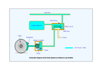
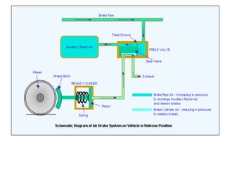
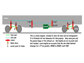
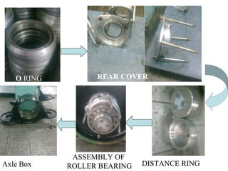

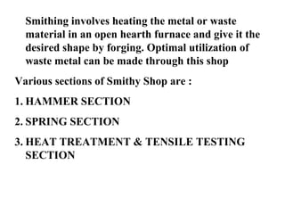
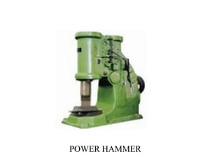
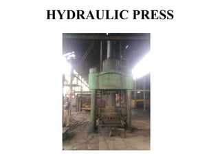
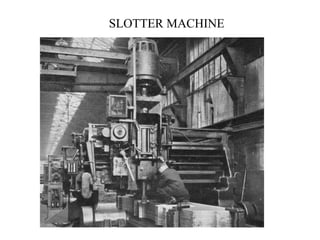
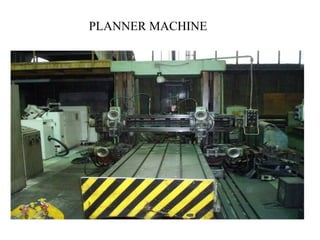

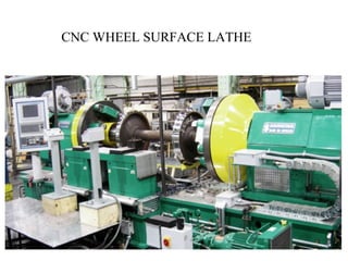
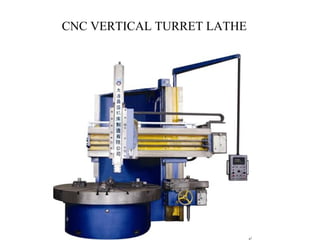
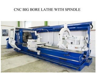
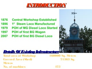

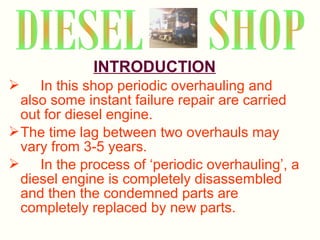


The document details the periodic overhauling process and maintenance operations for coach frames, diesel engines, and various mechanical components like braking systems and bogies. It includes descriptions of specific parts, their functions, and the assembly techniques used in the repair process. The workshop's infrastructure, including machine specifications and historical milestones, is also outlined.