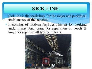
Downloaded 246 times


![Buffer height adjustment
Causes of low buffer height in ICF coaching stock :
a) excessive wear of wheel
b) Due to loss of proper stiffness of coil spring
c) Due to excessive wear on side bearer’s metal & bronze piece.
Maximum buffer height = 1105 mm [In empty condition]
Minimum buffer height = 1030 mm [In loaded condition]
To achieve buffer height a standard size of wooden packing pieces are used
which are kept below the Dash Pot Flange on axle Box wings of primary
suspension.
Serial N0. Wheel Diameter (mm) Thickness of Wooden Packing (mm)
1. Below 889 up to 863 13
2. Below 863 up to 839 26
3. Below 839 up to 819 38
4. 819 & below 48](https://image.slidesharecdn.com/amitppt-151004200417-lva1-app6891/85/SUMMER-TRAINING-PPT-On-Coach-Care-Centre-SICK-LINE-10-320.jpg)

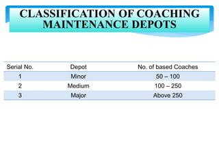
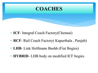
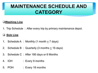
This document discusses the maintenance schedules and processes for different types of coaches in India. It provides the following key details: 1. Coaches are classified as minor, medium or major depending on their capacity of 50-100, 100-250, or above 250 passengers respectively. 2. Maintenance depots are categorized as integral coach factory (ICF), rail coach factory (RCF), link holfmann bushh (LHB), or hybrid depending on the coach design and components. 3. Regular maintenance includes washing after every trip and sick line maintenance on monthly, quarterly, or six month schedules depending on the coach category. 4. The sick line workshop performs repairs and overhauls like


