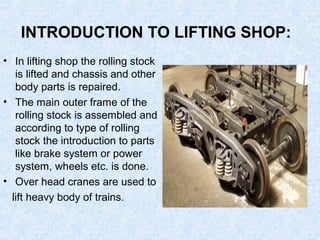
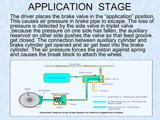
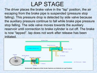
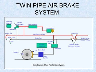
Call Girls in Dwarka Mor Delhi Contact Us 9654467111
RAILWAY WORKSHOP TRANING PPT
1. Training Report Presentation
on
Carriage & wagon workshop, Jagadhri
PRESENTED BY:
Sahil Arora
ROLL NO. 1213422
MECHANICAL ENGINEERING
SETH JAI PARKASH MUKAND LAL INSTITUTE OF ENGINEERING &
TECHNOLOGY , RADAUR, YAMUNA NAGAR
2. JAGADHRI WORKSHOP
INTRODUCTION
• The foundation stone of workshop is laid on
08/02/1952.
• Repairing of broad gauge rolling stock i.e.
wagon and coaches.
• Target of 1150 units of wagon and 135 coaches
per month.
• Main objective of company is to provide best
maintenance for railway coaches.
• Main shops on workshop includes carriage bogie
shop, roller bearing shop, wheel shop, A.C
electrician shop, paint shop, wagon shop .
3. INTRODUCTION TO LIFTING SHOP:
• In lifting shop the rolling stock
is lifted and chassis and other
body parts is repaired.
• The main outer frame of the
rolling stock is assembled and
according to type of rolling
stock the introduction to parts
like brake system or power
system, wheels etc. is done.
• Over head cranes are used to
lift heavy body of trains.
4. CLASSIFICATION OF ROLLING
STOCK :
• LOCOMOTIVE:-the vehicle containing the source of
power to pull the train is called locomotive. Usually
attached in front of train.
• COACHES :- Vehicles designed for carrying passengers
are called coaches. In addition , certain vehicles
attached to passenger trains are also covered under the
coaches. These includes postal vans, inspection
carriages, etc.
• WAGONS:- Vehicles designed for carrying commodities
are called wagons. These may be open , covered, flat,
tanks etc depending on material to be carried.
5. CNC PLASMA CUTTER
Plasma cutting is a process that is
used to cut steel and other metals of
different thicknesses (or sometimes
other materials) using a plasma torch.
In this process, an inert gas (in some
units, compressed air) is blown at
high speed out of a nozzle; at the
same time an electrical arc is formed
through that gas from the nozzle to
the surface being cut, turning some of
that gas to plasma. The plasma is
sufficiently hot to melt the metal being
cut and moves sufficiently fast to
blow molten metal away from the cut.
7. VACUUM BRAKE SYSTEM
As the term indicates vacuum is the moving is the
working medium. The equipment consists of a vacuum brake
cylinder with piston and brake rigging provided under each
vehicle. The amount of vacuum maintained on one side of
piston in the vacuum cylinder to operate the brake System IS
about the 29 Inch of mercury which gives an effective working
pressure of about 100 Lbs per Square inch on the piston
when brake are applied. The 'vacuums, Cylinder are designed
to give the required amount of brake power at the wheel the
vacuum cylinders are continuously evacuated by exhausters
provided the locomotive.
8. AIR BRAKE SYSTEM
• In this, Compressed Air is used for operating the brake
system.
• The locomotive compressor charges the feed pipe and
the brake pipe throughout the length of the train.
• The feed pipe is connected to the auxiliary reservoir and
the brake pipe is connected to the brake cylinder through
the distributor valve.
• Brake application takes place by dropping the pressure in
the bakes pipe.
• TYPES OF AIR BRAKE SYSTEM
1. Single-pipe air brake system
2. Twin-pipe air brake system
10. OPERATIONS IN AIR BRAKE
SYSTEM
Consists of Three Stages: -
• Release Stage
• Application Stage
• Lap Stage
11. RELEASE STAGE
The driver places the brake valve in the “release” position.
Pressure in the brake pipe is rising and enters the triple valve
on each car, pushing the side valve towards left. The
movement allows a feed groove to open between brake pipe
and auxiliary reservoir and another connection bellow it to open
between brake cylinder and exhaust port. The pressurized air
recharges the auxiliary cylinder and air pressure in brake
cylinder escapes through exhaust port . The spring get released
and brake block comes back to its position.
12. The driver places the brake valve in the “application” position.
This causes air pressure in brake pipe to escape. The loss of
pressure is detected by the side valve in triplet valve
,because the pressure on one side has fallen, the auxiliary
reservoir on other side pushes the valve so that feed groove
get closed. The connection between auxiliary cylinder and
brake cylinder get opened and air get feed into the brake
cylinder. The air pressure forces the piston against spring
and causes the break block to attach the wheel.
APPLICATION STAGE
13. LAP STAGE
The driver places the brake valve in the “lap” position, the air
escaping from the brake pipe is suspended (pressure stop
falling). This pressure drop is detected by side valve because
the auxiliary pressure continue to fall while brake pipe pressure
stop falling. The side valve moves towards the auxiliary
reservoir until connection to brake cylinder is cut off. The brake
is now “lapped”. lap does not work after release has been
initiated.