Downloaded 454 times
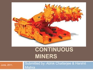

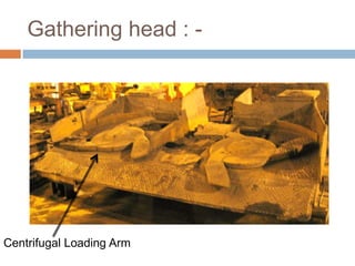
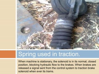
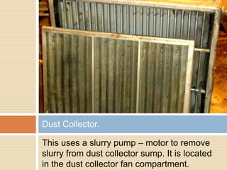
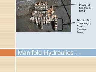
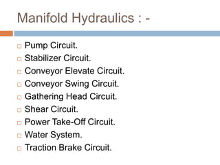

The document discusses continuous miners used in underground mining. It describes the JOY continuous miner product line which includes three machine classes for different mining heights: 14CM, 12CM, and 12HM series. Key components of the continuous miners are described, including the cutter, gathering head, conveyor, traction, dust collector, hydraulics, and electrical systems. Specifications for the Joy 12CM15 continuous miner used in two mining projects are also provided.