Downloaded 326 times
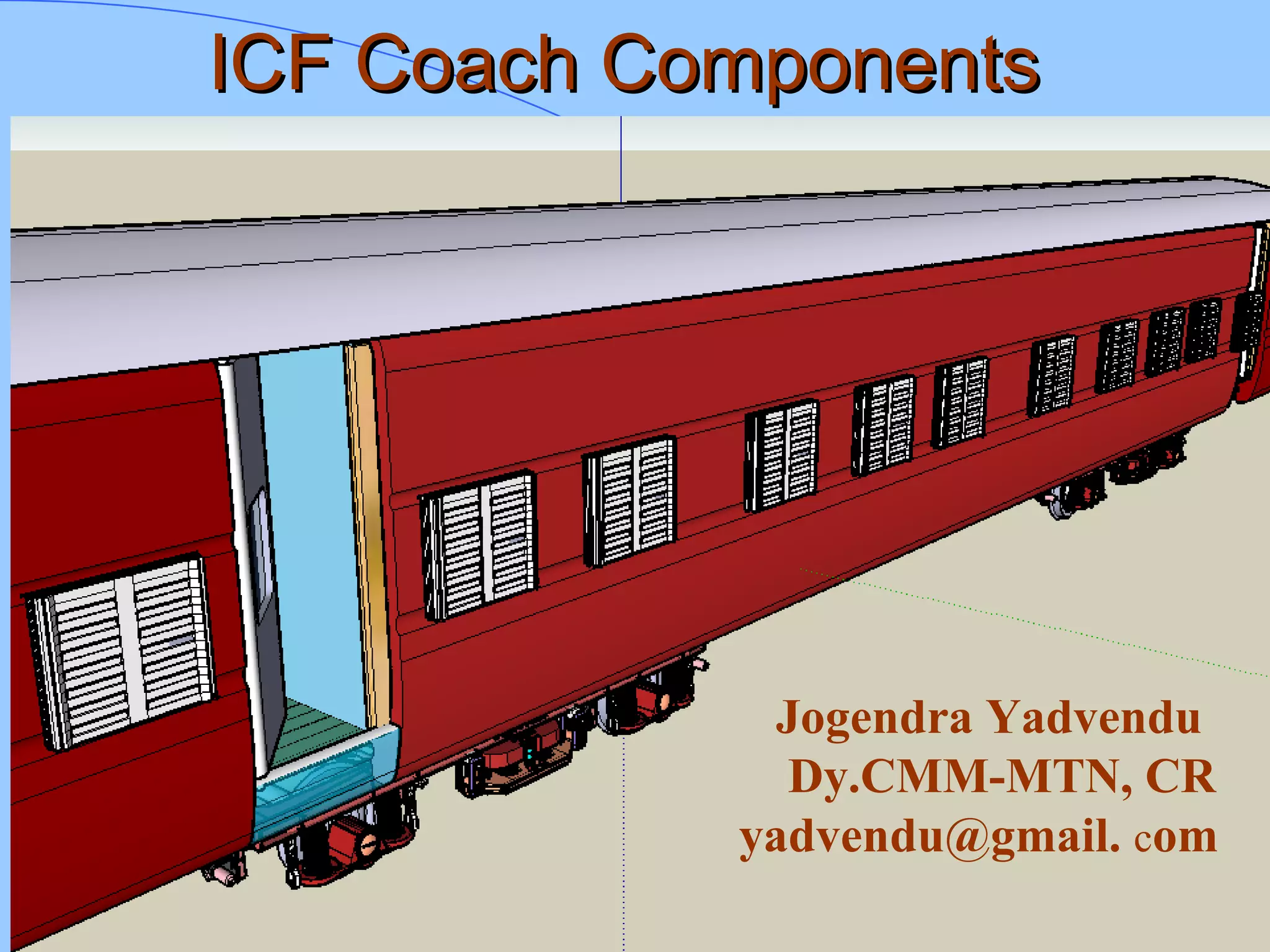


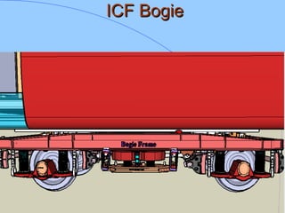
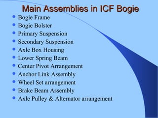
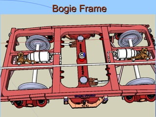
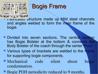
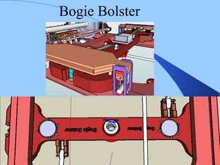
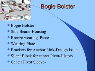
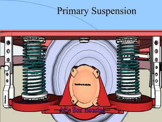
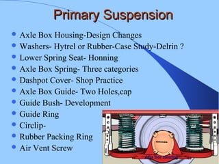
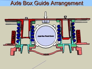
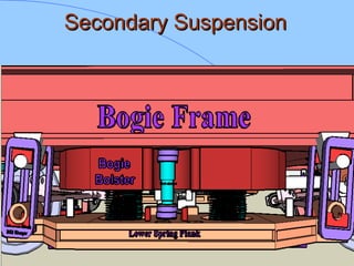
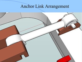
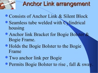
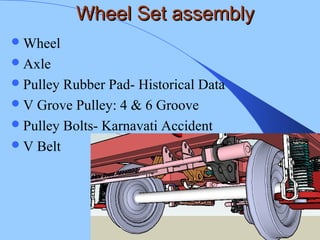
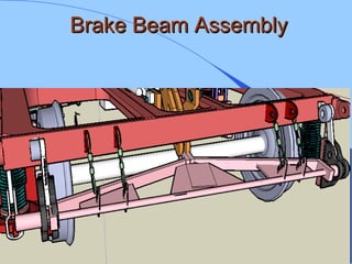
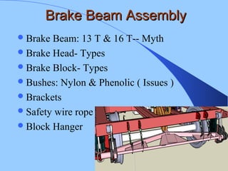
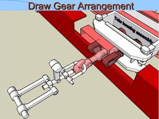
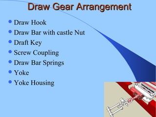
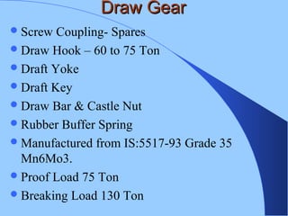

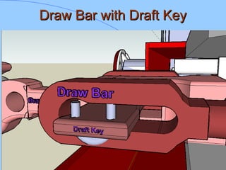
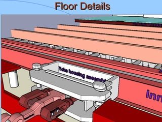
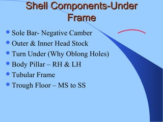
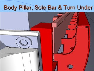
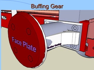
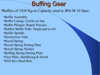
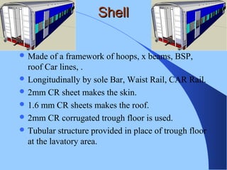

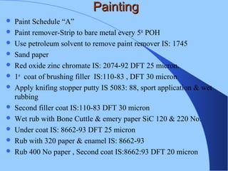

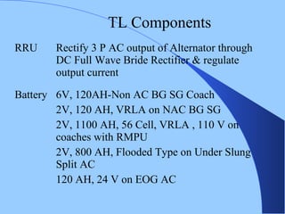
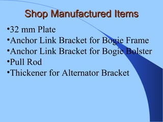
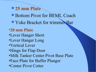
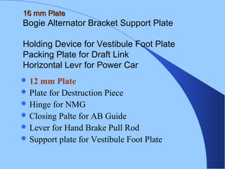


The document discusses various components of ICF coaches including bogies, rolling gear, brake systems, and underframes. It provides detailed descriptions and specifications for sub-components of the dust bin, bogie frames, suspension systems, wheel assemblies, air brakes, headstocks, and buffing gear. It emphasizes the importance of understanding the products being procured and their individual parts in order to effectively manage materials.