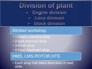
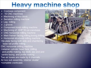
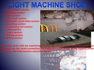
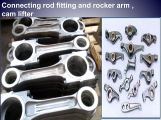
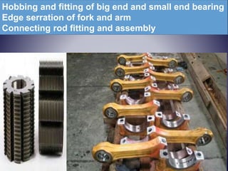
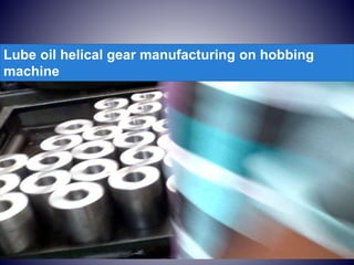
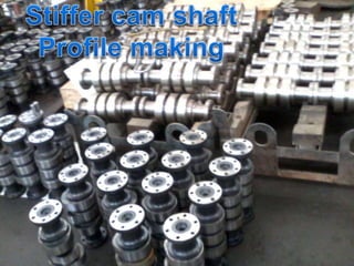
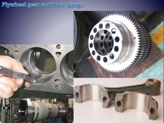
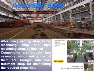
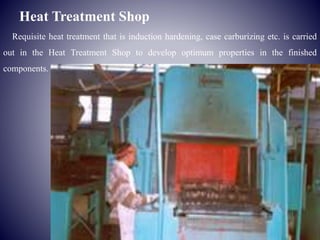
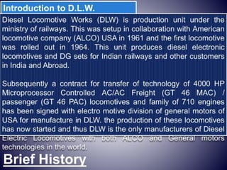
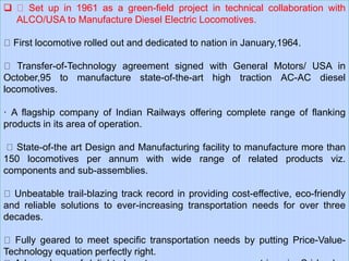
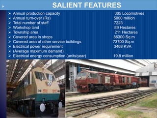
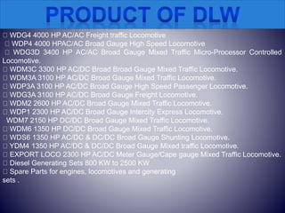
Four Weeks Industrial Training seminar at,
Acknowledgement
I would sincerely like to thank the employees and the officers of DLW, VARANASI for
their help and support during the vocational training. Despite their busy schedules, they
took time out for us and explained to us the various aspects of the working of the plant,
from the production shops.
I would sincerely like to thank Shree Ravi Shankar, AlokSingh (CWI/TTC) and Mr. Sunil
Kumar(JE/H.W.S.), Mr. VinodKumar (JE/Rotor Shop) who was instrumental in arranging
the vocational training at DLW Varanasi, and without whose help and guidance the
training could not have materialized.
I express my deep sense of gratitude to Mr. R. R. Jha (Principal, TTC) for given me such a great
opportunity.
Introduction to D.L.W.
Brief History
 Set up in 1961 as a green-field project in technical collaboration with
ALCO/USA to Manufacture Diesel Electric Locomotives.
First locomotive rolled out and dedicated to nation in January,1964.
Transfer-of-Technology agreement signed with General Motors/ USA in
October,95 to manufacture state-of-the-art high traction AC-AC diesel
locomotives.
· A flagship company of Indian Railways offering complete range of flanking
products in its area of operation.
State-of-the art Design and Manufacturing facility to manufacture more than
150 locomotives per annum with wide range of related products viz.
components and sub-assemblies.
Unbeatable trail-blazing track record in providing cost-effective, eco-friendly
and reliable solutions to ever-increasing transportation needs for over three
decades.
Fully geared to meet specific transportation needs by putting Price-Value-
Technology equation perfectly right.
 SALIENT FEATURES
 Annual production capacity 305 Locomotives
 Annual turn-over (Rs) 5000 million
 Total number of staff 7223
 Workshop land 89 Hectares
 Township area 211 Hectares
 Covered area in shops 86300 Sq.m
 Covered area of other service buildings 73700 Sq.m
 Electrical power requirement 3468 KVA
 (Average maximum demand)
 Electrical energy consumption (units/year) 19.8 million
WDG4 4000 HP AC/AC Freight traffic Locomotive
WDP4 4000 HPAC/AC Broad Gauge High Speed Locomotive
WDG3D 3400 HP AC/AC Broad Gauge Mixed Traffic Micro-Processor Controlled
Locomotive.
WDM3C 3300 HP AC/DC Broad Broad Gauge Mixed Traffic Locomotive.
WDM3A 3100 HP AC/DC Broad Gauge Mixed Traffic Locomotive.
WDP3A 3100 HP AC/DC Broad Gauge High Speed Passenger Locomotive.
WDG3A 3100 HP AC/DC Broad Gauge Freight Locomotive.
WDM2 2600 HP AC/DC Broad Gauge Mixed Traffic Locomotive.
WDP1 2300 HP AC/DC Broad Gauge Intercity Express Locomotive.
WDM7 2150 HP DC/DC Broad Gauge Mixed Traffic Locomotive.
WDM6 1350 HP DC/DC Broad Gauge Mixed Traffic Locomotive.
WDS6 1350 HP AC/DC & DC/DC Broad Gauge Shunting Locomotive.
YDM4 1350 HP AC/DC & DC/DC Broad Gauge Mixed traffic Locomotive.
EXPORT LOCO 2300 HP AC/DC Meter Gauge/Cape gauge Mixed Traffic Locomotive.
Diesel Generating Sets 800 KW to 2500 KW
Spare Parts for engines, locomotives and generating
sets .
NOMENCLATURE OF LOCOMOTIVE
The code is of the form
[gauge][power][load][series][suffix]
GAUGE-
W(BROAD)
Y (METRE)
Z (NARROW,2.6’)
N (NARROW,2’)
POWER-
D = Diesel
C = DC traction
A = AC traction
CA = Dual-power AC/DC
B = Battery electric (rare)
LOAD-
P=passenger
G=goods
M=mixed both AC and DC
SERIES
3=3000HP
4=4000HP
5=5000HP
SUFFIX
A=100HP
B=200HP
C=300HP
D=400HP
Allotted workshop
• 1-Heavy machine shop
• 2-light machine shop
• 3-Rotor shop
• 4-Heat treatment shop
HMS, LMS,ROTOR,HTS
• Each shop has been described in next
slide.
 Crankase component
 10 CNC machines
 Machining of Alco block
 Serration milling machine
 Leg milling
 J groove
 Component knob milling machine
 Machining of HHP 16 cyl.cranckase
 CNC horizontal milling machine
 Main frame= facing,milling,boring,drilling
 Horizontal structural milling machine
=tie plate facing both side and chamfering
base rail profile milling
CNC horizontal drilling machine
=retainer cylinder head face milling
and profile making, top deck, sec end and
centre facing and profile making
Two air boxes are made by 4 channels
Air box sub assembly, retainer cluster
=complete crankcase.
Bore making by radial drilling machine
Formation of hole by ultrasonic cutting
Engine Blocks of diesel locomotives and Traction Motor Magnet
Frames are machined in this shop. Precision machining of the Blocks is
carried out on CNC Horizontal Boring & Milling Machine of PAMA,
Italy make CNC machine.
Serration milling
machine
Engine view
 Econometric section
 Grinding section
 Gear section
 Cam shaft section
 Automatic turret lathe section
 Benching section
 Connecting rod section
 Lathe section
 Liners section
 Drilling section
 Milling section
This shop deals with the machining of small component required for the power pack
Unit such as cam shaft,connecting rod,liners,gears,levers,fuel pump support,piston
Pins,nuts and bolts,bushes,various shaft etc.
Connecting rod fitting and rocker arm ,
cam lifter
Hobbing and fitting of big end and small end bearing
Edge serration of fork and arm
Connecting rod fitting and assembly
Lube oil helical gear manufacturing on hobbing
machine
Flywheel shaft gear and lube oil pump gear
This shop deals with the manufacturing of Turbocharger
and its various component
Impeller
Inducer
Nose piece
Stud rotor
Nut
Washer
Thrust washer
Key
 oil slinger
Turbine disc
Turbo shaft
Lock plate
Turbocharger
3 main parts
1-rotor
2-compressor
3- casing
After heavy welding shop, heavy
machining shop and light
machining shop, all finished
Components are brought into
assembly shop and some of
them are brought into heat
treatment shop for maintaining
the required properties.
Heat Treatment Shop
Requisite heat treatment that is induction hardening, case carburizing etc. is carried
out in the Heat Treatment Shop to develop optimum properties in the finished
components.
 Cam shaft (MG,BG)
 Push rod
 Yoke air exhaust
 Shaft valve lever
 Adjusting screw yoke
 Adjusting screw cross head
 Adjusting screw lever
 Yoke guide
 Nut cam shaft
 Fulcrum pin push rod
 Impeller gear
 Main piston pin
 Cam roller cross head
 Cam roller push rod
 Drive shaft
 Alco shaft
 Pin cam roller
 Pin fuel cam roller cross head
 General motor piston pin
 Fuel pump cross head body
 Stiffer cam shaft
 U cam leab
 Spare bearing
 Seat
 Thrust valve
Stress releiving process
Temperature=450*c for 4 hours
Component- Alco cam shaft
Hardening=
If carbon % is below from 0.4 %
General hardening 800-840*c
Induction hardening=
Magnetic flux
Eddy current
Heating coil
Water as a coolant
Tempering=
200 degree per hours
Rate 1 inch per hour
Carburizing= case depth=50 thou
1-Pack carburizing 4 thou per hrs
2-Gas carburizing
Normalizing=800*c air cooling
If carbon % is below from 0.4% then hardening is not possible .
For hardening ,carbon%>0.4% ,the temperature ranges from 800
Degree Celsius to 840 degree Celsius generally,
For general hardening ,when temperature reaches limiting
range, after one or one half an hour, parts are quenched hurry.
For tempering temperature ranges from 200 degree Celsius to
450 degree Celsius .when temperature of the parts reaches at
Limiting range ,it is remained at this temperature for 4 hours and
Then they are cooled in furnace slowly.
Parts are heated up to 800 degree Celsius, and then these are
Cooled in environment slowly.
ROHIT KUMAR BHARDWAJ MADHUBAN MAU

ROHIT KUMAR BHARDWAJ MADHUBAN MAU

  • 1.
    Four Weeks IndustrialTraining seminar at,
  • 2.
    Acknowledgement I would sincerelylike to thank the employees and the officers of DLW, VARANASI for their help and support during the vocational training. Despite their busy schedules, they took time out for us and explained to us the various aspects of the working of the plant, from the production shops. I would sincerely like to thank Shree Ravi Shankar, AlokSingh (CWI/TTC) and Mr. Sunil Kumar(JE/H.W.S.), Mr. VinodKumar (JE/Rotor Shop) who was instrumental in arranging the vocational training at DLW Varanasi, and without whose help and guidance the training could not have materialized. I express my deep sense of gratitude to Mr. R. R. Jha (Principal, TTC) for given me such a great opportunity.
  • 3.
  • 4.
     Set upin 1961 as a green-field project in technical collaboration with ALCO/USA to Manufacture Diesel Electric Locomotives. First locomotive rolled out and dedicated to nation in January,1964. Transfer-of-Technology agreement signed with General Motors/ USA in October,95 to manufacture state-of-the-art high traction AC-AC diesel locomotives. · A flagship company of Indian Railways offering complete range of flanking products in its area of operation. State-of-the art Design and Manufacturing facility to manufacture more than 150 locomotives per annum with wide range of related products viz. components and sub-assemblies. Unbeatable trail-blazing track record in providing cost-effective, eco-friendly and reliable solutions to ever-increasing transportation needs for over three decades. Fully geared to meet specific transportation needs by putting Price-Value- Technology equation perfectly right.
  • 5.
     SALIENT FEATURES Annual production capacity 305 Locomotives  Annual turn-over (Rs) 5000 million  Total number of staff 7223  Workshop land 89 Hectares  Township area 211 Hectares  Covered area in shops 86300 Sq.m  Covered area of other service buildings 73700 Sq.m  Electrical power requirement 3468 KVA  (Average maximum demand)  Electrical energy consumption (units/year) 19.8 million
  • 6.
    WDG4 4000 HPAC/AC Freight traffic Locomotive WDP4 4000 HPAC/AC Broad Gauge High Speed Locomotive WDG3D 3400 HP AC/AC Broad Gauge Mixed Traffic Micro-Processor Controlled Locomotive. WDM3C 3300 HP AC/DC Broad Broad Gauge Mixed Traffic Locomotive. WDM3A 3100 HP AC/DC Broad Gauge Mixed Traffic Locomotive. WDP3A 3100 HP AC/DC Broad Gauge High Speed Passenger Locomotive. WDG3A 3100 HP AC/DC Broad Gauge Freight Locomotive. WDM2 2600 HP AC/DC Broad Gauge Mixed Traffic Locomotive. WDP1 2300 HP AC/DC Broad Gauge Intercity Express Locomotive. WDM7 2150 HP DC/DC Broad Gauge Mixed Traffic Locomotive. WDM6 1350 HP DC/DC Broad Gauge Mixed Traffic Locomotive. WDS6 1350 HP AC/DC & DC/DC Broad Gauge Shunting Locomotive. YDM4 1350 HP AC/DC & DC/DC Broad Gauge Mixed traffic Locomotive. EXPORT LOCO 2300 HP AC/DC Meter Gauge/Cape gauge Mixed Traffic Locomotive. Diesel Generating Sets 800 KW to 2500 KW Spare Parts for engines, locomotives and generating sets .
  • 7.
    NOMENCLATURE OF LOCOMOTIVE Thecode is of the form [gauge][power][load][series][suffix] GAUGE- W(BROAD) Y (METRE) Z (NARROW,2.6’) N (NARROW,2’) POWER- D = Diesel C = DC traction A = AC traction CA = Dual-power AC/DC B = Battery electric (rare) LOAD- P=passenger G=goods M=mixed both AC and DC SERIES 3=3000HP 4=4000HP 5=5000HP SUFFIX A=100HP B=200HP C=300HP D=400HP
  • 8.
    Allotted workshop • 1-Heavymachine shop • 2-light machine shop • 3-Rotor shop • 4-Heat treatment shop HMS, LMS,ROTOR,HTS • Each shop has been described in next slide.
  • 9.
     Crankase component 10 CNC machines  Machining of Alco block  Serration milling machine  Leg milling  J groove  Component knob milling machine  Machining of HHP 16 cyl.cranckase  CNC horizontal milling machine  Main frame= facing,milling,boring,drilling  Horizontal structural milling machine =tie plate facing both side and chamfering base rail profile milling CNC horizontal drilling machine =retainer cylinder head face milling and profile making, top deck, sec end and centre facing and profile making Two air boxes are made by 4 channels Air box sub assembly, retainer cluster =complete crankcase.
  • 10.
    Bore making byradial drilling machine Formation of hole by ultrasonic cutting
  • 11.
    Engine Blocks ofdiesel locomotives and Traction Motor Magnet Frames are machined in this shop. Precision machining of the Blocks is carried out on CNC Horizontal Boring & Milling Machine of PAMA, Italy make CNC machine.
  • 12.
  • 16.
  • 18.
     Econometric section Grinding section  Gear section  Cam shaft section  Automatic turret lathe section  Benching section  Connecting rod section  Lathe section  Liners section  Drilling section  Milling section This shop deals with the machining of small component required for the power pack Unit such as cam shaft,connecting rod,liners,gears,levers,fuel pump support,piston Pins,nuts and bolts,bushes,various shaft etc.
  • 19.
    Connecting rod fittingand rocker arm , cam lifter
  • 20.
    Hobbing and fittingof big end and small end bearing Edge serration of fork and arm Connecting rod fitting and assembly
  • 21.
    Lube oil helicalgear manufacturing on hobbing machine
  • 24.
    Flywheel shaft gearand lube oil pump gear
  • 27.
    This shop dealswith the manufacturing of Turbocharger and its various component Impeller Inducer Nose piece Stud rotor Nut Washer Thrust washer Key  oil slinger Turbine disc Turbo shaft Lock plate
  • 29.
  • 31.
    After heavy weldingshop, heavy machining shop and light machining shop, all finished Components are brought into assembly shop and some of them are brought into heat treatment shop for maintaining the required properties.
  • 32.
    Heat Treatment Shop Requisiteheat treatment that is induction hardening, case carburizing etc. is carried out in the Heat Treatment Shop to develop optimum properties in the finished components.
  • 33.
     Cam shaft(MG,BG)  Push rod  Yoke air exhaust  Shaft valve lever  Adjusting screw yoke  Adjusting screw cross head  Adjusting screw lever  Yoke guide  Nut cam shaft  Fulcrum pin push rod  Impeller gear  Main piston pin  Cam roller cross head  Cam roller push rod  Drive shaft  Alco shaft  Pin cam roller  Pin fuel cam roller cross head  General motor piston pin  Fuel pump cross head body  Stiffer cam shaft  U cam leab  Spare bearing  Seat  Thrust valve
  • 34.
    Stress releiving process Temperature=450*cfor 4 hours Component- Alco cam shaft Hardening= If carbon % is below from 0.4 % General hardening 800-840*c Induction hardening= Magnetic flux Eddy current Heating coil Water as a coolant Tempering= 200 degree per hours Rate 1 inch per hour Carburizing= case depth=50 thou 1-Pack carburizing 4 thou per hrs 2-Gas carburizing Normalizing=800*c air cooling
  • 39.
    If carbon %is below from 0.4% then hardening is not possible . For hardening ,carbon%>0.4% ,the temperature ranges from 800 Degree Celsius to 840 degree Celsius generally, For general hardening ,when temperature reaches limiting range, after one or one half an hour, parts are quenched hurry. For tempering temperature ranges from 200 degree Celsius to 450 degree Celsius .when temperature of the parts reaches at Limiting range ,it is remained at this temperature for 4 hours and Then they are cooled in furnace slowly. Parts are heated up to 800 degree Celsius, and then these are Cooled in environment slowly.