Downloaded 289 times

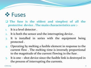
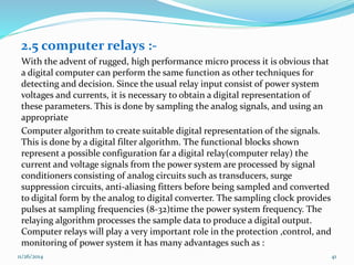
![The force which tries to pull the plunger inside the coil given
by
푓푚 =
훅
훅푥
w` 푖, 푥 = 푘
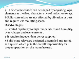
푖2
푔푑
4푎
푥+
2 ……………(2.2)
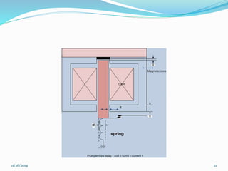
Where k is a constant depending upon constants of the
magnetic circuit shown on the figure .
The plunger moves when 푓푚 exceeds 푓푠 .if the current is
sinusoidal with an rms value of I ,the average force is
proportional to I² . The valve of the current (퐼푝) at which the
plunger just begins to move is known as the pickup setting of
the replay is given by :
퐼²
푓푚 = 푓= 푘
푝푠 푔푑
4푎
(푥 +
)²
then
퐼푝=[
푓푠
푘
] x +
푔푑
4푎
… … … … ……(2.3)
11/26/2014 22](https://image.slidesharecdn.com/relayoperationprinciples-141126065914-conversion-gate01/85/Relay-operation-principles-22-320.jpg)
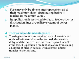
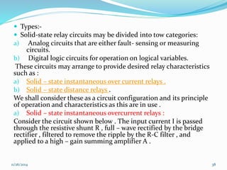
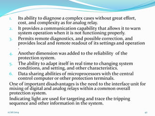
![Where x is the displacement of the plunger when no
current is flowing in the coil (stating position ). The
plunger travels some distance from x to x1 before it
closes its contacts and hits a stop . The energizing
current must drop below a value 퐼푑 , known as the
dropout current before the plunger can return to tis
original position x . The dropout current is given by :
퐼푑=[
푓푠
푘
] 푥1 +
푔푑
4푎
… … … … ……(2.4)
퐼푑<퐼푝 푎푠 x < 푥1
11/26/2014 23](https://image.slidesharecdn.com/relayoperationprinciples-141126065914-conversion-gate01/85/Relay-operation-principles-23-320.jpg)
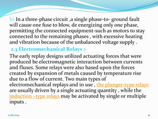
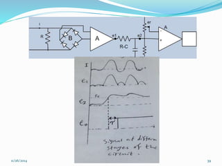
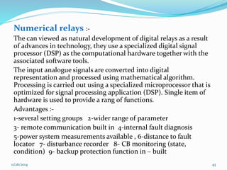
![The operating time of the relay depends upon the mass of the
plunger .
For a normalized current of magnitude 퐼푛 (actual current divided
by the pickup current ), the accelerating force on the plunger is :
퐼퐼2
F=퐹푛 푃
푚 − 퐹푆 = 푘
푔푑
4푎
푋+
2 − 퐹푠 , substituting for 퐼푝 from equation
(2.3) then ,
F= 퐹푠[
(푥0+푔푑/4푎)²
푔푑
4푎
(푥+
)²
퐼푛² − 1] … … … … (2.5)
The equation of motion for the plunger is ,
M푋 = -F …………….(2.6)
Where m is the mass of the plunger.
Equation (2.6)can be integrated twice to provide the operating
time of the relay (the time it takes the plunger to travel from
푥 푡표 푥1). The integrals in eqn (2.6) are elliptic integrals and must be
evaluated numerically for given displacements .
11/26/2014 24](https://image.slidesharecdn.com/relayoperationprinciples-141126065914-conversion-gate01/85/Relay-operation-principles-24-320.jpg)
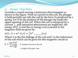
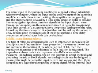
![Sol: use the sam construction of plunger-type relay was given
in section (2.3)then :
a)From eqns (2.3)and(2.4),we have for dimension in cm:-
푔푑
퐼(푥+
)
푑
1 4푎
(0.7 + 0.05)
=
=
= 0.714
퐼푝
(푥0+푔푑/4푎)
(1 + 0.05)
b)From eqn (2.5),the accelerating force F is :
F=퐹푠
푥0+
푔푑
4푎
2
푥+
푔푑
4푎
2 퐼푛
2
− 1 = 0.001
1.05 2
푥+0.005 2 2 2 − 1
F=0.001
4.41
0.7225
− 1 = 5.1 × 10⁻³N.
c)Using eqns (2.5)and (2.6) them
0.005 푥 =-0.001[
(1.05)²
(푥+0.005)²
퐼푛² -1 ]= -F
11/26/2014 26](https://image.slidesharecdn.com/relayoperationprinciples-141126065914-conversion-gate01/85/Relay-operation-principles-26-320.jpg)
![The operating time can be calculated using a constant force
equal to the average taken over its travel from 푥0푡표 푥1 then
from the above eqn use x= 푥0 =1cm and x= 푥1=0.7 cm and
calculate F in both cases.
For x= 1cm
퐹1 = 0.001( 퐼푛² - 1 ) newton
For x= 0.7cm
퐹2 = 0.001(1.96 퐼푛² - 1 ) newton
Fav = 0.001(1.48 퐼푛² - 1 )newton
Using this expression for the force ,then the approximate
equation of motion for the plunger is :
0.005푥 = −0.001[1.48 퐼푛² - 1 ]
푥 = 0.2[1.48 퐼푛² − 1 ]
11/26/2014 27](https://image.slidesharecdn.com/relayoperationprinciples-141126065914-conversion-gate01/85/Relay-operation-principles-27-320.jpg)
![푥1 푑푥 = 0.2[1.48 퐼푛² - 1 ] 0
푥0
푡
푑푡
t²=
10(푥0−푥1)
1.48 퐼푛² − 1
Or t =
10(푥0−푥1)
1.48 퐼푛² − 1
=
0.3
1.48 퐼푛² − 1
=
0.3
0.48
= 0.79 sec. approximately
This relation shows the inverse –time behavior of the relay for
larger values of 퐼푛 and can be drown for 퐼푛 ≥ 1 .
Most plunger relays also have several taps available on the
winding of the coil to adjust the pickup current over a wide
range (tap setting 1,2,….10 amperes ). Also the pickup can be
controlled by adjusting the plunger within the coil. Plunger –
type relays will operate on dc as well as on ac current .
11/26/2014 28](https://image.slidesharecdn.com/relayoperationprinciples-141126065914-conversion-gate01/85/Relay-operation-principles-28-320.jpg)
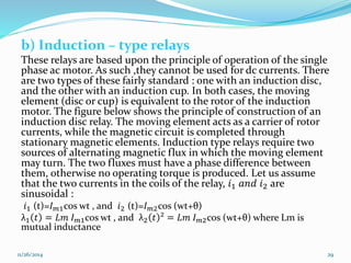
![Each of these flux linkages in turn induces a voltage in the
rotor, and since the rotor is a metallic structure with low self-inductance,
a rotor current in phase with the inducted
voltages flows in the rotor. Assuming the equivalent rotor
resistance to be 푅1, the induced rotor current are given by :
푖푟1 푡 =
1
푅푟
푑λ1
푑푡
= -
ω퐿푚퐿푚1
푅푟
sin ωt ………….(2.7)
푖푟2 푡 =
1
푅푟
푑λ2
푑푡
= -
ω퐿푚퐿푚2
푅푟
sin (ωt+θ) ………….(2.8)
Each of the rotor current interacts with the flux produced by
the other coil, producing a force. The two forces are in
opposite direction w.r.t each other, and the net farce, or the
corresponding net torque T is given by :
T [λ1 푖푟2-λ2푖푟1 ], substituting for λ,i and simplify to get
T= k 퐼푚1 퐼푚2 [cos ωt+θ)-cos(ωt+θ)sin ωt] ……….(2.9)
11/26/2014 31](https://image.slidesharecdn.com/relayoperationprinciples-141126065914-conversion-gate01/85/Relay-operation-principles-31-320.jpg)
![For φ=2˚=0.035 radian, in tegreting the equation of motion
twice to get θ=5(퐼푛² − 1)푡² and the operating time of the
relay is
t=
0.035
5(퐼푛²−1)
sec
c) The operation time after relay closes its contact (퐼푛 ≥ 1)
take 퐼푛= 1.01 then
t =
0.035
= 0.59 sec
5[ 0.01 2−1]
11/26/2014 35](https://image.slidesharecdn.com/relayoperationprinciples-141126065914-conversion-gate01/85/Relay-operation-principles-35-320.jpg)

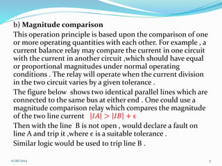
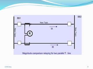
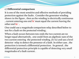
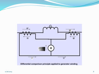
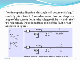
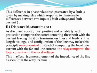
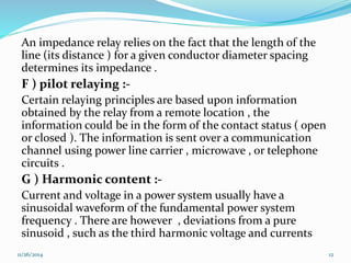
This document describes various principles of relay operation used in power systems. It discusses several categories of relays including level detection relays, magnitude comparison relays, differential relays, phase angle comparison relays, distance relays, pilot relays, harmonic content relays, and frequency sensing relays. It also describes some common relay designs such as plunger-type electromechanical relays and their operating characteristics. Relay principles can be based on detecting changes in current, voltage, phase angles, harmonic components, or frequency during fault conditions.


