This document discusses different methods for measuring force, including scales and balances, elastic force meters, load cells, proving rings, and dynamometers. It provides details on the principles and workings of various force measurement devices:
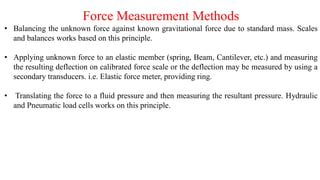
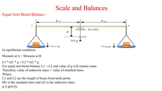
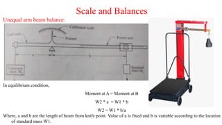
- Scales and balances measure force by balancing an unknown force against a known gravitational force using standard masses. Unequal arm beam balances relate the length of the beam to the measured force.
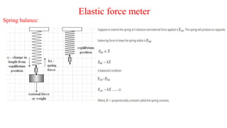
- Elastic force meters measure the deflection of an elastic member like a spring when an unknown force is applied and relate it to the measured force.
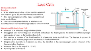
- Load cells translate an applied force into a fluid pressure that is then measured, allowing highly accurate force measurement. Hydraulic and pneumatic load cells work on