Okay, here are the steps to solve this parallel circuit problem:
1) Total Current (I1) = Sum of branch currents
I1 = I1 + I2 + I3
I1 = 2A + 1A + 0.5A
I1 = 3.5A
2) Total Voltage (E1) = Voltage across each branch
E1 = E1 = E2 = E3
E1 = 120V
3) Total Resistance (R1) using Ohm's Law
P1 / I1 = E1 / R1
Power / Total Current = Voltage / Total Resistance
120V / 3.5A = E1 / R1
Fire Alarm Systems fall broadly into two groups - Conventional Systems or Analogue Addressable Systems.
• Conventional Fire Alarm Control System
• Analogue Addressable Fire Alarm System
Intelligent Addressable Fire Alarm System
This presentation provides you basic information about Fire Detection and Alarm System (FDAS). It includes fire detection and alarm system devices, inspection, drawings and maintenance.
Fieldbus Tutorial Part 7 - Fieldbus CommunicationEmerson Exchange
Fieldbus Tutorial Part 7 – Fieldbus Communication: Foundation Communications Stack, Communication Between Devices, Expected H1 Performance, High Speed Ethernet Support
• Medium Velocity Water Spray Systems (MVWSS) are used for fire protection of areas with fire risks from low FP flammable liquids (FP below 65 Degree C) and also for fire extinguishment of water miscible liquids (polar solvents, alcohols etc.) small installation as it becomes cost effective and also serves the purpose of safety and location identification is easy.
• High Velocity Water Spray Systems (HVWSS) are used for extinction of fires in flammable medium and heavy oils or similar flammable liquids having a flashpoint above 65 Degree C. (E.g. Transformer Fires, Lube Oil Tanks, Etc).
PREMIUM BOOK WITH HIGH DEFINITION QUALITY.
**A complete Guide of Fire fighting System.**
This HANDBOOK has been made from references of many books from all over the world. Which has been collected in one book.
1. Sprinkler system Type
WET PIPE SPRINKLER SYSTEM
DRY PIPE SPRINKLER SYSTEM
PRE-ACTION SYSTEM
DELUGE SYSTEM
WET PIPE ANTI FREEZE SYSTEM
FOAM WATER SPRINKLER SYSTEM
2. Sprinkler Selection
3 . Piping
4. Hydraulic Calculation
5. Standpipe System
6. Pump Selection & Types
العدالة في التخطيط: يهدف هذا المشروع إلى جمع وتحليل المعلومات، ورفع الوعي حول غياب العدالة في توزيع الموارد العامة بين المناطق العمرانية المختلفة؛ مع دراسة الأسباب المؤسسية التي تؤدي لتكريس هذا الوضع في مصر (وخاصة في إقليم القاهرة الكبرى).
ولتحقيق هذا الهدف، يسعى المشروع لتطوير أدوات لقياس عدم العدالة في توزيع الموارد العامة، وكيفية التعامل مع هذا الوضع، كذلك يهدف إلى توفير هذه الأدوات للمجموعات الأخرى المهتمة بهذا المجال في مصر.
Fieldbus Tutorial Part 4 - Installation of FieldbusEmerson Exchange
Fieldbus Tutorial Part 4 – Installation of Fieldbus: Foundation Physical Layer, Choosing Components and Layout, System Design, Field Checkout and Commissioning, Trouble Shooting a Fieldbus System
Fundamental training on Fire Detection & Alarm SystemSabrul Jamil
This is a basic training on Fire Detection and Alarm System, created to give my colleagues from non-engineering divisions a comprehensive brief on the system. This is most suitable for individuals with little or no technical knowledge. This training introduces the devices and the system in a whole, not how to design it.
EPLAN is an electrical engineering software program, developed for the management, documentations and planning of electrical design projects. EPLAN's products range from fluid engineering and process plant engineering to harness and enclosure design. This presentations gives an overview of EPLAN, demonstrating how the software can enhance the quality of documentation, reduce time to market and increase overall productivity.
Output equation of Induction motor; Main dimensions; Separation of D and L; Choice of Average flux density; length of air gap; Design of Stator core; Rules for selecting rotor slots of squirrel cage machines; Design of rotor bars and slots; Design of end rings; Design of wound rotor; Magnetic leakage calculations; Leakage reactance of polyphase machines; Magnetizing current; Short circuit current; Operating characteristics; Losses and Efficiency.
A numerical problem wherein the total inductance of an electromechanical energy conversion device is calculated furthermore the effect of changing the airgap length on the static force is also observed
Unit 8 - Information and Communication Technology (Paper I).pdfThiyagu K
This slides describes the basic concepts of ICT, basics of Email, Emerging Technology and Digital Initiatives in Education. This presentations aligns with the UGC Paper I syllabus.
Introduction to AI for Nonprofits with Tapp NetworkTechSoup
Dive into the world of AI! Experts Jon Hill and Tareq Monaur will guide you through AI's role in enhancing nonprofit websites and basic marketing strategies, making it easy to understand and apply.
Acetabularia Information For Class 9 .docxvaibhavrinwa19
Acetabularia acetabulum is a single-celled green alga that in its vegetative state is morphologically differentiated into a basal rhizoid and an axially elongated stalk, which bears whorls of branching hairs. The single diploid nucleus resides in the rhizoid.
Read| The latest issue of The Challenger is here! We are thrilled to announce that our school paper has qualified for the NATIONAL SCHOOLS PRESS CONFERENCE (NSPC) 2024. Thank you for your unwavering support and trust. Dive into the stories that made us stand out!
Synthetic Fiber Construction in lab .pptxPavel ( NSTU)
Synthetic fiber production is a fascinating and complex field that blends chemistry, engineering, and environmental science. By understanding these aspects, students can gain a comprehensive view of synthetic fiber production, its impact on society and the environment, and the potential for future innovations. Synthetic fibers play a crucial role in modern society, impacting various aspects of daily life, industry, and the environment. ynthetic fibers are integral to modern life, offering a range of benefits from cost-effectiveness and versatility to innovative applications and performance characteristics. While they pose environmental challenges, ongoing research and development aim to create more sustainable and eco-friendly alternatives. Understanding the importance of synthetic fibers helps in appreciating their role in the economy, industry, and daily life, while also emphasizing the need for sustainable practices and innovation.
How to Make a Field invisible in Odoo 17Celine George
It is possible to hide or invisible some fields in odoo. Commonly using “invisible” attribute in the field definition to invisible the fields. This slide will show how to make a field invisible in odoo 17.
Model Attribute Check Company Auto PropertyCeline George
In Odoo, the multi-company feature allows you to manage multiple companies within a single Odoo database instance. Each company can have its own configurations while still sharing common resources such as products, customers, and suppliers.
Biological screening of herbal drugs: Introduction and Need for
Phyto-Pharmacological Screening, New Strategies for evaluating
Natural Products, In vitro evaluation techniques for Antioxidants, Antimicrobial and Anticancer drugs. In vivo evaluation techniques
for Anti-inflammatory, Antiulcer, Anticancer, Wound healing, Antidiabetic, Hepatoprotective, Cardio protective, Diuretics and
Antifertility, Toxicity studies as per OECD guidelines
1. t-
sg,s # Ess#$s ss$'sffi $w#ss
"' .' i#BY 'flii
GEORGE V. HART
'It'' ' 'tttttt tD'r,Eo
.,,;:.;,,
....---"-.i
WILLIAM C. BUCHANAN
ruED-f' -o
2. ffi A note from the author...
W UGLY'S ELECTRICAL REFERET{CES iS
ffi
:- designed to be used as a quick on-the-job refer-
-3116 once in the electrical industry. We have tried to
_1t4 (
.t".?t
*,,, include the most commonly required informa-
=;3 tion in an easy-to-read format.
-3t4
=,:lE ,,, (lgly's Electrical References is not intended
=
to be a substitute for the National Electrical
=
Code'.
- We salute the National Fire Protection
-
(, ,1 , ,a
Association for their dedication to the protection
- of lives and property from fire and electrical
r)t!
-u
=
hazards through sponsorship of the National
=
Electrical Code'-
- NATIONAL ELECTRICAL CODE'AND NEC@ ARE REGISTERED TRADEMARKS OF THE
-
NATI0NAL FIRE PROTECTI0N ASSOCIAT|0N, lNC., OUINCY MA.
nll
Disclaimer...
=
' '*hile the author and publisher of UGLI"S
_ ELECTRICAL REFEREI,{CES have made
- efforts to insure that all information in this book
is clear and accurate, neither author nor publish-
-
_ 4" er shall be held responsible for any effors in con-
=
tent; nor shall they be responsible for the inter-
_ pretation or application of material in this book. -
-
=
ISBN 0-e62322e-7-0
t-il
3. r::i:l&,
diiililffiii
ffil
W::
ffi:l
w''
ffi&ffi#wffiffffiffiK ffiffiwffiffiffiffiffiffiffi
by
GEORGE V. HART
and
SAMMIE HART
WILLIAM C. BUCHANAN
Editor
COPYRIGHT, 1978 BY GEORGE HART (AUTHOR)
COPYRIGHT, 2OO5 BY RON BURLESON
REVISED 1gg1 , 1994, 1987 , 1990, 1993, 1996, 1999, 2002,2005
PRINTED IN U.S.A.
THIS BOOK MAY NOT BE REPRODUCED IN ANY FORM WITHOUT THE
PRIOR WRITTEN PERMISSION OF THE COPYRIGHT HOLDER
Gr,D
'e$#YD''
DISTRIBUTED BY:
Burleson Distributing Corp. .3501 Oak Forest Drive . Houston, Texas 77018
(713) 956-6666 . (800) 531-1660 . Fax (713) 956-6576
E-mail : uglys@uglys.net
4. TABLE OF CONTENTS
RULER - INCH INSIDE FRONT COVER
OHM'SLAW ....1 -z
SERIESCIRCUITS ...3-4
PARALLEL CIRCUITS .5 .7
COMBINATION C|RCU|TS . .8 - 12
COMMON ELECTRICALDISTRIBUTIONSYSTEMS... ..13-14
ELECTRICALFORMULAS ....15
TO FIND:
AMPERES (t) . .16 _ 1e
HORSEPOWER (HP) .20 - 21
WATTS(P) ......22
K|LO-WATTS (KW) ...23_24
KrLO-VOLT-AMPERES(KVA) ...25
cApActTANCE (C), AND CAPACTTORS .26 - 29
POWER FACTORCORRECTION ,...29
POWERFACTOR/EFFICIENCYEXAMPLE... ...30
TNDUCTANCE(L) .......31
TMPEDANCE(Z) ...32
REACTANCE (INDUCTIVE (XL) AND CApACtTtVE (XC) . . . . . .33
RESISTOR COLORCODE .....34
MOTORS:
RUNNING OVERLOAD UNITS
BRANCH CIRCUIT PROTECTIVE DEVICES
DIRECT CURRENT
FULL-LOAD CURRENT
DIRECT CURRENT MOTORS .
STNGLE PHASE (A.C.):
FULL-LOADCURRENT ....38
USING STANDARD THREE PHASE STARTER . . . . .39
SINGLEPHASEMOTORS . ...40-41
THREE-PHASE MOTORS (A.C.):
FULL-LOAD CURRENT .42-44
GENERALMOTOR RULES ......44
BRANCH CIRCUIT& FEEDER EXAMPLE ....45
LOCKED ROTORTABLES ,...46-47
MOTORWINDINGS&CONNECTIONS ......48
THREE WIRE STOP.START STATION , .49
TWOTHREE WIRE STOP-STARTSTATIONS . . . . . .50
HAND OFF AUTOMATIC CONTROL . . . .51
JOGGING WITH CONTROL RELAY . . . .52
.....35
.....35
.....36
.....37
5. TABLE OF CONTENTS (continued)
TRANSFORMERS:
CALCULATIONS . . .53
VOLTAGE DROP CALCULATIONS .....54-57
SHORTCIRCUITCALCULATIONS... ..58.61
SINGLE-PHASECONNECTIONS .....62
BUCK& BOOSTCONNECTIONS ....63
FULLLOADCURRENTS ......64
THREE-PHASE CONNECTIONS .65 - 69
MISCELLANEOUSWIRING DIAGRAMS ....70-71
CONDUCTOR PROPERTIES . .72
A.C. RESISTANCE & REACTANCE FOR 600 VOLT CABLES . .73
ALLOWABLE AMPACITIES OF CONDUCTORS . . . .74 - 78
AMPACITY CORRECTION & ADJUSTMENT FACTORS . .78 - 79
INSULATION CHARTS ....79-82
MAXIMUM NUMBER OF CONDUCTORS IN CONDUIT / TUBING:
GENERAL CALCULATION PROCEDURE . . .83
ELECTRICALMETALLICTUBING .....84- 85
NONMETALLICTUBING ...86-87
RIGID PVC CONDUIT, SCHEDULE 40 . . .88 - 89
RIGIDPVCCONDUIT,SCHEDULESO .. .....90-91
RIGID METALLICCONDUIT .....92-93
FLEXIBLE METALLIC CONDUIT . .94 - 95
LIQUIDTIGHT FLEXIBLE METALLIC CONDUIT . . . . .96 - 97
DIMENSIONS OF INSULATED CONDUCTORS . . . . .98 - 99
COMPACTALUMINUM BLDG. WIRE DIMENSIONS . . . .1OO
DIMENSIONS & PERCENTAREAOF CONDUIT ..101 - 103
TABLES:
TAP, DRILL BIT AND HOLE SAW TABLES . .104
METALBOXES ...105
MINIMUM COVER REQUIREMENTSTO 600 VOLI-S ........106
VOLUME REQUIRED PER CONDUCTOR . .106
VERTICALCONDUCTORSUPPORTS .....106
CLEAR WORKING SPACE ]N FRONT OF
ELECTRICAL EQUIPMENT .107
MINIMUM CLEARANCE OF LIVE PARTS . .108
MIN. SIZE EQUIP. GROUNDING CONDUCTORS .109
GROUNDING ELECTRODECONDUCTOR .....110
GENERAL LIGHTING OCCUPANCY LOADS
LIGHTING LOAD DEMAND FACTORS .....111
DEMAND FACTORS FOR NONDWELLING . .112
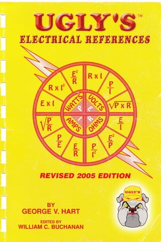
7. OHM'S LAW
The rate of the flow of the current is equal to
electromotive force divided by resistance.
I = lntensity of Current = Amperes
E = Electromotive Force - Volts
R = Resistance-Ohms
P = Power=Watts
The three basic Ohm's law formulas arei
E-lxR
Below is a chart containing the formulas related to Ohm's law.
To use the chart, from the center circle, select the value you need to
find, I (Amps), R (Ohms), E (Volts) or P (Watts). Then select the
formula containing the values you know from the corresponding chart
quadrant.
Example:
An electric appliance is rated at 1200 Watts, and is connected to 1 20
Volts. How much current will it draw?
E
R=f
E
rL-
l
--
IT
R
Ampere. =ffi r=+ ,=W =1oA
What is the Resistance of the same appliance?
ohms =9 R =E R -
120
-12t)
Amperes I 10
-1
VPTR
8. OHM'S LAW
ln the preceding example, we know the following values:
| -amps =10
E =voltS -120
R=ohms -12{l
P = watts - 1200
We can now see how the twelve formulas in the Ohm's Law chart
can be applied.
AMPS =
AMPS = ffi
AMPS = +fi#F
wATTs = +fiffi-
WATTS = V0LTSxAMPS
WATTS = AMPS'xOHMS
. i-P- m0-
I
-
t-
' -v R -v 12
r=+=W=1oA
r=+=+=1oA
p= {= 4 =
14:!oo
=12oow
r- R 12 12
P= Exl = 120x10 = 1200W
P = l'xR=100x12 = 1200W
=^F; = 1oA
volTs =@ E =1FR-=f1200x12 =f14/-m=120V
V0LTS = AMPSxOHMS E = lxR = 10x12 = 120V
VOLTS =
WATTS
AMPS
E= + =
T39 = 12ov
OHMS =
OHMS =
OHMS =
VOLTS,
f,lrA-TTtr
WATTS
nrulP'St
VOLTS
E,
=P
P
=T
E
=T
120' 14,400
= 12c-
T2o-o- = Tod- = tLsz
ffi=na
#=na
AMPS
9. SERIES CIRCUITS
A SERIES ClRCUlr is a circuit that has only one path through
which the electrons may flow.
RULE 1: The total current in a series circuit is equal to the current in
any other part of the circuit.
T0TAL GURRENT 11 = 11 - lz= 13, BlG.
RULE 2: The total voltage in a series circuit is equal to the sum of the
voltages across all parts ol lhe circuit.
T0TAL VOLTAGE Er = Er + Ez + E3, etc.
RULE 3: The total resistance ol a series circuit is equal to the sum ol
the resistances of all the parts ol the circuit
TOTAL RESISTANCE Rr = Rr + Rz + R3, BtG.
FORMULAS FROM OHM'S LAW
AMPEREs=ffi oR
RESISTANCE = J9L OR
.
AMPERES
V0LTS = AMPERES x RESISTANCE 0R
EXAMPLE: Find the total voltage, total current, and total resistance of
the following series circuit.
1O VOLTS
0.4 AMPS
25 OHMS
.E
I
--
|-R
R=+
E=lxR
E2=
lz=
Rz=
E1 = 8 VOLTS
Ir = 0.4 AMPS
R1 = 20 OHMS
tr
r-3 -
13=
R3=
6 VOLTS
0.4 AMPS
1 5 OHMS
Er-?
lr=?
Rr=?
3=
(continued next page)
10. SERIES CIRCUITS
lT=
lT=
Er=
=
tT=
Er+E2+E3
8 + 10 + 6
24 VOLTS
tr, - 2
lt-?
R1 = 72 OHMS
E2 = 12 VOLTS
12=?
R2= ?
Er-?
lr - lr = 12-ls-lo
lT -11 =12=0.5-14
0.5=0.5=0.5=0.5=0.5
lr = 0.5 AMPS lz = 0.5 AMPS
11 = 0'5 AMPS l+ = 0.5 AMPS
Er - E1 +Ez+ Es +E+
=36+12+24+48
Er - 120 VOLTS
Rr-R1+Rz+Rs+R+
=72+24+48+96
Rr - 240 OHMS
E12
D_
-
t-2
'-z 12 0.5
R2 - 24 OHMS
11-12-1.
0.4-0.4=0,4
0.4 AMPS
E4 = 48 VOLTS
14=?
R4=?
Rr-?
=lrxRr
= 0.5 x72
= 36 VOLTS
Rr=Rt+R2+R3
-20+25+15
Rr = 60 OHMS
EXAMPLE: Find Er, Er, E3, lr, lr , ',2,
/4, R1, R2, AND R4.
Remember that the total current in a series circuit is equal to the
current in any other part of the circuit.
Eg=?
ls = 0.5 AMPS
R3 = 48 OHMS
lr=?
E1
E1
E3 =lgxRg
=0.5x48
E3 - 24 VOLTS
_E4 _48
14 - 0.5
= 96 OHMS
R4
R4
-4
11. PARALLEL CIRCUITS
A PARALLEL CIRCUIT is a circuit that has more than one path
through which the electrons may flow.
RULE 1: The total current in a parallel circuit is equal to the sum of the
currents in all the branches ol the circuit.
TOTAL CURRENT 11 = 11 + 12 + 13, GtG.
RULE 2: The total voltage across any branch in parallel is equal to the
voltage across any other branch and is also equal to the total
voltage.
TOTAL VOLTAGE E1 = E1 'Ez= Es, etc.
RULE 3: The total resistance ol a parallel circuit is lound by applying
0HM'S LAW to the total values ol the circuit.
ToTALREstsTANGE=ffi oR RT=+
rT
Example; Find the total current, total voltage, and total resistance of the
following parallel circuit.
Er=120V
lj =2AMP
Rr = 60 0HMS
l_
rl
=
lT=
11+12+13
2 + 1.5 + 1
4.5 AMPS
ET = Er=Ez-E3
= 120 = 120 = 120
Er = 120 V0LTS
tr
Rr= +
lT
120 VOLTS A Ar rr ,A ^FArA-^ rrAF
= aiffi = 26'66 0HMS RESISTANOE
NOTE: ln a parallel circuit, the total resistance is always less than the
resistance of any branch. lf the branches of a parallel circuit have
the same resistance, then each will draw the same current. lf the
branches of a parallel circuit have different resistances, then each
will draw a different current. ln either series or parallel circuits, the
larger the resistance, the smaller the current drawn.
Ez= 120 V
lz = 1'5 AMP
Rz = 80 0HMS
Es=120V
ls=1AMP
Rs = 120 0HMS
12. 1111
x-i=ff;+n,+E
1111 I -.1-
Rr 60'80'120
1 4 + 3 + 2 I
PARALLEL CIRCUITS
To determine the total resistance in a parallel circuit when the total
current and total voltage are unknown:
1111
ffi = T; + R,*:R, ANDETC'
EXAMPLE: Find the total resistance of the following circuit:
Ei=T =uo
_L-.-_--_9
E)=zO
cross multiPlY'
9xRT=1x240or9Rr=240
divide both sides of the equation by g
Rr = 26.66 OHMS RESISTANCE
Use lowest common denominator (240).
NOTE: The total resistance of a number of EQUAL resistors in parallel is
equal to the resistance of one resistor divided by the number of resistors.
TOTAL RESISTANCE =
RESISTANCE OF ONE RESISTOR
NUMBER OF RESISTORS IN CIRCUIT
Rr = 60 OHMS Rz = 80 OHMS Rs = 120 0HMS
(continued next page)
13. PARALLEL CIRCUITS
FORMULA:
EXAMPLE: Find the total resistance
There are three resistors in parallel. Each has a
value of 120 OHMS resistance. According to the
formula, if we divide the resistance of any one of
the resistors by three, we will obtain the total
resistance of the circuit.
RT=+ oR Rr = +
TOTAL RESISTANCE = 40 OHMS.
N0TE: To find the total resistance of only two resistors in parallel, multiply
the resistances, and then divide the product by the sum of the resistors.
Rr =+
FORMULA:
EXAMPLE:
ToTAL REStsTANcE = *#
RT
RrxRz
R1+R2
40x80
40 + B0
3200
1n=
7-
RT
Rz = 80 OHMS
26.66 0HMS
14. COMBINATION CIRCUITS
ln combination circuits, we combine series circuits with parallel circuits.
Combination circuits make it possible to obtain the different voltages of
series circuits, and the different currents of parallel circuits.
EXAMPLE 1. PARALLEL.SERIES CIRCUIT:
Solve for all missing values.
Es=?
ls=?
Ra = 10 OHMS
En=?
ln=?
a
R+ = 50 0HMS
TO SOLVE:
1. Find the total resistance of each branch. Both branches are simple
series circuits, so
R1+R2=RA
20 + 40 = 60 OHMS total resistance of branch "A"
R3+R4=RB
10 + 50 = 60 OHMS total resistance of branch "8"
2. Re-draw the circuit, c0mbining resistors (Rr + R2) and
(Rs + R4) so that each branch will have only one resistor.
I
3
Er = 120
VOLTS
5
lr=? 2
Rr=? #
m
t
T
=
Er = 120 V0LTS -
t -t O
fT-: z
R-=?
,E
m
L
tr _c
LB-:
I _C
rB - :
Re = 60 OHMS
(continued next page)
t-
El=? =l
=? F
Rr = 20 0HMS
E
z
F^=? t
-r,
_'o m
t2- ! I
'Rz = 40 OHM1
15. coMBTNAT|ON QtRCUITS
NOTE: We now have a simple parallel circuit, so
Er=EA=EB
120V = 120V = 120V
We now have a parallel circuit with only two resistors, and they are of equal
value. We have a choice of three different formulas that can be used to
solve for the total resistance of the circuit.
(1)
Rr =
RAXRB 60 x 60 3600
(2) When the resistors of a parallel circuit are of equal value,
RA+RB
tr
LA
T;
11 = lz
tr
LB
=
RB
13 =14
60 + 60 120
oR f#= 2
=2
=2
=2
= 30 OHMS
OR
lA = 2 AMPS
11 = 2 AMPS
lB = 2 AMPS
13 = 2 AMPS
l4 = 2 AMPS
(continued next page)
Rr = + = ry = 3ooHMS
(3) 1 1 11 1 r_ 1 2 1
RTRA'R360'606030
p=G oR 1 x Rr = 1 x 30 oR Rr = 3ooHMS
3. We know the values 0f E1, Rr, EA, RA, EB, Rs, Rt , Rz,R3, and Ra.
Next we will solve for 11, lA, lB, 11,12, 13, and 14.
rr = + oR Hq= 4 rr=4AMps
lA
lA
lB
lB
0R 2 = 2
0R f#
0R 2 = 2
16. 4.
COMBINATION CIRCUITS
We know that resistors #1 and #2 of branch "A" are in series. We
know too that resistors #3 and #4 oI branch "8" are in series. We
have determined that the total current of branch "A" is 2 AMPS, and
the total current of branch "B" is 2 AMPS. By using the series formula,
we can solve for the current of each branch.
BRANCH "A"
lA=11 =lz
2 = 2 = 2
11 = 2 AMPS
12 = 2 AMPS
BRANCH "8"
lB=lA=14
2 = 2= 2
13 = 2 AMPS
14 = 2 AMPS
5. We were given the resistance values of all resistors.
R1 = 20 0HMS, R2 = 40 OHMS, R3 = 10 0HMS, and R4 = 50 0HMS.
By using 0HM'S Law, we can determine the voltage drop across each
resistor.
Er=R1 x11
= 20x 2
El = 40 VOLTS
Ez = R2 x lz
= 40x 2
E2 = B0 V0LTS
EXAMPLE 2: SERIES PARALLEL CIRCUIT.
Solve for all missing values.
Es=Rsxlg
= 10 x 2
E3 = 20 V0LTS
E4 = R4 x 14
=50x2
E4 = 100 V0LTS
Er=?
=?
Rr = 10
F^-?
-J
ls=?
Rs=30
BRANCH ,,A''
Er = 110 V0LTS
I _O
IT- !
Rr=?
Ez=?
lz=?
Rz=20
10
(continued next page)
17. COMBINATION CIRCUITS
To solve:
1. We can see that resistors #2 and #3 are in parallel, and combined
they are branch "A". When there are only two resistors, we use the
following formula:
RA= RzxRs
R2+R3
0R;3# oR
H oR 12 oHMS
2. We can now re-draw our circuit as a simple series circuit.
F.-2
ll=?
Rr = 10 0HMS
3. ln a series circuit,
RT = R1 + RA 0R RT = 10 + 12 0R 220HMS
By using 0HM'S Law,
rT = += W=sAMPS
ln a series circuit,
lT = h = lA 0r lT = 5AMPS, h = 5AMPS, and lA = 5AMPS
By using 0HM'S Law,
E1 = h x R1 = 5 x 10 = 50V0LTS
Er -E1 -EA or 110 50 = 60V0LTS = EA
ln a parallel circuit,
EA = Ez = EB 0r EA = 60 VQLTS
E2 = 60 V0LTS, and E3 = 60 V0LTS
By using 0HM'S Law,
Er = 110 V0LTS
=?
Rr=?
tz = += #=3AMPS
t3 = += #=2AMPS
11
(continued next page)
18. COMBINATION CIRCUITS
PROBLEM:
Solve for total resistance.
Re-draw circuit as many times as necessary.
Correct answer is 100 0HMS.
Branch "A"
G IVEN VALUES:
R1 = 15 0HMS
R2 = 35 0HMS
R3 = 50 OHMS
R4 = 40 0HMS
R5 = 30 0HMS
R6 = 25 OHMS
R7 = 10 0HMS
RB = 300 0HMS
Re = 60 OHMS
12
19. COMMON ELECTRICAL DISTRIBUTION SYSTEMS
120' r Volt Single Phase Three Wire System
t . Line one ungrounded conductor colored Black.
t . Line two ungrounded conductor colored Red.
**. Grounded neutral conductor colored White or Gray.
120 ' Uolt Three Phase Fout Wlre System (Delta High Legl
*B Hi hLe Oran ef
Red
240 Black
1201v
t
240 volts
t
240 volts
o lts
Neutral ts wtite..
1 . A phase ungrounded conductor colored Black.
t* . B phase ungrounded conductor colored Orange or tagged
(High Leg). (Caution - 208V Orange to White)
t . C phase ungrounded conductor colored Red.
**. Grounded conductor colored White or Gray. (Center tap)
**
Grounded conductors are required to be white or gray or three white stripes. See NEC 200.6A.
-
B phase of high leg delta must be Orange or tagged.
f Ungrounded conductor colors may be other than shown; see local ordinances or specifications.
1 20 volts
1 20 volts 240 volts
208 v
+
13
20. CCIMMON E!-ECTRICAL DISTBIBUTION SYSTEMS
120/ q8 volt Three Phase Four wire System {wYE Connected}
t . A phase ungrounded conductor colored Black.
t . B phase ungrounded conductor colored Red.
t . G phase ungrounded conductor colored Blue.
**. Grounded neutral conductor colored White or Gray.
2771480 llolt Three Phase Four Wire System (WYE Gonnected)
rownt
480 volts
Pur leI
t
277 volts 480 volts
Yellow
t . A phase ungrounded conductor colored Brown.
t . B phase ungrounded conductor colored Purple
t . C phase ungrounded conductor colored Yellow.
**. Grounded neutral conductor colored G ray.
.*
Giounded conductors are required to be white or gray or three white stripes. See NEC 200.6A.
-B
phase of high leg delta must be Orange or tagged.
f Ungrounded conductor colors may be other than shown; see local ordinances or specifications.
- 14 -
Black I
F Redt
120 volts
120 volts
208 volts
208 volts
277 volts
Neutral i
-.-Grav..
21. F
z,
III
E
0c
CJ
(5
z,
<
1
t
IJI
5
L T
CA
J-
o-
III
tu
E
F
c)
F
x
lr
o-
x
lJ.
ll
IJJ
s
x
ul
(0
sf
F
x
o-
J.
lc'r
o lr
8l-
rlX
x lu-
=li
ol
Flq
xl-
s l,i
Yl
oal
F-l
JI
#le
*l-
xl
rul
col
l
-lo
x18
IF
xl
url
ct
X
LL
o-
X
lJ-
tr
tJl
-O
6i
Ix
ul
(O
N
CY)
rcD
E
o 6'e
^ r.r.r
Ct
- (/)
r-r:C f
o-otr
U^
tuc!z^,
g4-^"
r t-r X,;
*o3 q9
zF],
ee29
psFs
=3[E
Ef=<
o>><
u-Et=
+OrH
zrr-oil
HHts
E < t_t_tY
=-cn*
oo-<a-
xqE'
E9gH
-_>!
Og)FF
lr-i
F
o
z
=
l<
= lE
il
^t
Ek
=
l=
;1tr
ur lE
qlf,.'
-lt
cc l<
LU IO-
e l*
o_l
il
LL
o_
il
E.
o
F
o
tr
E.
ul
=
o
o-
9lo
5l=
lv
tr lr-
i lf
=12
ol
il
lJ-
tL
tu
s
ll
o
z
tu
o
tL
LL
UJ
F
z
uJ
.O
tr
u
(L
IJJ
E
=
CE
J
€
l&
I
trl
@
!
CL
€
I
F
lnr
lx
Iu-
slo
tslx
x lu-
*lF
I,i
EIT
F IIJ-
xlL
=lx
v llrr
ol
el
PI*
xlx
gl'
Il
tls
xle
IF
nl
*l
xlo
-!e
XIP
*l
$t
X
lJ.
o
X
tL
IT
tr.!
*
IX
tU
(O
=f
N
trt
a
E
o-
IJJ
J
C5
z,
ct)
lu
lo-
S I,l
*lh
+l*
l,x
ol
Fl*
xlx
=
I'r"r
vl
ol
ol
ol
rl
x lur
sl
vl
trl
o-I
*18
-lO
xl-
url
-lo
nlF
u-
&
X
L^L
II
ul
s
:X
UJ
(o
sf
N
F
bfr
llf e
t#
o=CJ
slffi
xlS
olx
-lt
ol
OI
ol
-!
xlu
=l
-l-
nlF
IL
IL
tJ,!
*
:x
ul
(.o
st
N
(:
z,
IL
o
F
vtLz
H-=
U
i-z,z,
==-
==e?
o2z
urCE
trya--
E.q A
EJ-
=
tr >1
=E-
o=2
HF=
=
=fr=
==c
CUt r-
r- O,
i-=
=o-
Oq,
:<c
hL
{or
+==
=:
cL
EF=
r- L
!Et ts
VEL EL
-=3
E
llt
=
o
o-
4l
ct)
E,
o
- 15 -
22. TO FIND AMPERES
DIRECT CURRENT:
A. When H}RSEP}WER is known:
AM'EREi^ H0RSEP0WER x 74F HP x 746
s= ori=ffi
What current will a travel-trailer toilet draw when equipped with a 12
volt, 1/8 HP motor, having a 96Yo efficiency rating?
! = =HP
*=l!9=
= 'T,4!
x=lLe
= gg- = 8.09 AMps
r - E x %EFF 12 x0.96 1TET
B. When KIL]WATTS are known:
AM'ERE' KIL0WATTS x 1000_ 0r I = _KWx1000
$= orl=ff
475 KW, 240 Volt, direct current generator is used to power a
variable-speed conveyor belt at a rock crushing plant.
Determine the current.
l
I =
KW x_ 1000
= 75 I _ _1 000
= g12.5 AM pS
E 240
SINGLE PHASE:
A. When WATTS, V]LTS, AND P]WER FACT}R are known:
AMPERES = or T+TF.
Determine the current when a circuit has a 1500 watt load, a power-
factor of 86%, and operates from a single-phase 230 volt source.
r=g= l99q= T.1BAMpS
' - 230 x 0.86 -197J-
- 16 -
23. TO FIND AMPERES
SINGLE PHASE:
B. When H}RSEP]WER is known:
AMPERES =
H0RSEP0WER x 746
rL, V0LTS x EFFICIENCY x POWER-FACT0R
Determine the amp-load of a single-phase,112 HP, 115 volt motor.
The motor has an efficiency rating of 92oh, and a power-factor of B0%.
I _ HP x 746 112 x 746 373
r - Ex%EFFxPF 115x0.92x0.80 84.64
I - 4.4 AMPS
C. When KIL]WATTS are known.
AMPERES = m or r= HP
A 230 Volt single-phase circuit has a 12KW power load, and operates
al B4o/o power-factor. Determine the current.
| = KW= x L0-00 = 11=x 1190 - 11q09
= 62 AMps
E x PF 230 x 0.84 193.2 vL tat
D When KIL7V1LT-AMPERE is known:
AM'ERES =
KIL0V0LT-4UIPI_RE x 1000 0r I _ KVAI 1000
VOLTS E
A 115 volt, 2 KVA, single-phase generator operating at full load will
deliver 17.4 AMPERES. (Prove.)
r- 2x-J9oo
= 2,qo=o
= fl. AMps
' - l1t -ITil
REMEMBER:
By definition, ?ffiperes is the rate of the flow of the current.
-17-
24. TO FIND AMPERES
THREE PHASE:
A. When WATTS, VjLTS, AND P]WER FACT}R are known:
AMPERES =
WATTS
0r
VOLTS x POWER-FACT0R x 1,73
r=+
E x PF x 1.73
Determine the current when a circuit has a 1500 watt load, a power-
factor of 86%, and operates from a three-phase, 230 volt source.
l=
' ExP
1 500
Fx1.7g = = g4n
I - 4.4 AMPS
B. When H}RSEP]WER is known:
AMPERES =
H0RSEP0WER x 746
VOLTS x EFFICIENCY x P0WER-FACTOR x 1.73
HP x 746
or l=
Determine the amp-load of a three-phase, 112 HB 230 volt motor.
The motor has an efficiency rating oI 92oh, and a power-factor of B0%.
, HP x 746 112 x 746
t=
E x %EFF x PF x 1.73 230 x .92 x .80 x 1.73
373
= = 1,27 AMPS
293
1 500
- 18 -
25. TO FIND AMPERES
THREE PHASE:
C. When KIL]WATTS are known:
AMPERES =
KILOWATTS x l tlllll
rL, voLTS x PowER-FAcroR x 1.79
or r=ffi
A 230 volt, three-phase circuit, has a 12KW power load, and operates
aI84o/o power-factor. Determine the current.
r = =KW=I
1o9o==
= = 1=?go=0,
E x PF x 1.73 230 x 0.84 x 1.73 334.24
I - 36 AMPS
D. When KIL]V}LT-AMPERE is known:
AM'ERES =
KILOVOLT:AMPE$E x 1000
=
KYA x.1!_00
Ex1.73 E x 1.73
A 230 Volt,4 KVA, three-phase generator operating at full load will
deliver 10 AMPERES. (Prove.)
KVAx1000 4x1000 4000
I-
lr
E x 1.73 230 x 1 .73 397.9
I - lOAMPS
NOTE: To better understand the preceding formulas:
1.TW0-PHASE CURRENT x 2 = SINGLE-PHASE CURRENT.
2.THREE-PHASE CURRENT x 1.73 = SINGLE-PHASE CURRENT
3.THE CURRENT IN THE COMMON CONDUCTOR OF A TWO-PHASE
(THREE WIRE) CIRCUtT tS 141To GREATER THAN ETTHER 0F
THE OTHER TWO CONDUCTORS OF THAT CIRCUIT.
- 19 -
26. TO FIND HORSEPOWER
DIRECT CURRENT:
412 volt motor draws a current of 8.09 amperes, and has an
efficiency rating of 96To. Determine the horsepower.
,,F, Exlx%EFF 12x8.09x0.96 93.19
nr=T = =W
HP = 0.1249 = 1/B HP
SINGLE-PHASE:
,,F, VOLTS x AMPERES x EFFICIENCY x P0WER FACT0R
nf=
A single-phase, 115 volt (AC) motor has an efficiency rating oI 92o/o,
and a power-factor of 80%. Determine the horsepower if the amp-
load is 4.4 amperes.
Hp =
Exlxf-"_EFFxPF
=
115x4.4 I.9.92x0.80
746 7 46
H'RSE''WER =
VOLTS x AMIEBES x EFFICIENCY
746
372.416
tr = 0'4992 = 1l2HP
HP =
TWO.PHASE:
r rF V0LTS x AMPERES x EFFICIENCY x P0WER FACTOR x 2
Hf=
Determine the horsepower of a two-phase, 230 volt (AC) motor. The
motor has an efficiency rating oI 92oh, a power-factor of 80%, and
an amp-load of 1 .1 amperes.
..F E x I x %EFF x PF x 2 230 x 1.1 x 0.92 x 0.8x2
Hl, = = 746
HP = 372A'1A
7f = 0'4992 = 112 HP
-24-
27. TO FIND HORSEPOWER
THREE-PHASE:
V0LTS x AMPERES x EFFICIENCY x POWER FACTOR x 1.73
HP=
746
A three-phase, 460 volt motor draws a current of 52 amperes. The
motor has an efficiency rating oI 94oh, and a power factor of B0%.
Determine the horsepower.
,,F, E x I x %EFF x PF x 1.73 460 x 52 x 0.94 x 0.80x1.73
lll'= 746 = 746
HP = 41 .7 HP
21
28. TO FIND WATTS
The.electrical power in any part of a circuit is equal to the current in
that part multiplied by the voltage across that part of the circuit.
A watt is the power used when one volt causes one ampere to flow
in a circuit.
One horsepower is the amount of energy required to lift 33,000
pounds,0ne foot, in one minute. The electrical equivalent of one
horsepower is 745.6 watts. One watt is the amount of energy
required to Ltl 44.26 pounds, one foot, in one minute. Watts is
power, and power is the amount of work done in a given time.
When V]LTS AND AMPERES are known.
POWER (WATTS) = VOLTS x AMPERES
A 120 volt AC circuit draws a current of 5 amperes. Determine the
power consu m ption.
P = E x I - 120 x 5 = 600WATTS
We can now determine the resistance of this circuit.
POWER = RESISTANCE x (AMPERES)'
P = R x 12 0r 600 = R x 25 divide both sides of equation by 2s
600
E =R or R=240HMS
0r
PowER=ffi or p=# or ooo=#
R x 600 = 120' or R =
1a:10=o
= 24 }HMS
600
NOTE: REFER TO THE FORMULAS OF THE OHM'S LAW CHART ON PAGE 1
22
29. TO FIND KILOWATTS
DIRECT CUBRENT
KILOWATTS =
VOLTS I-IIVIPERES
1 000
A 120 volt (DC) motor draws a current of 40 amperes.
Determine the kilowatts.
KW = !=l=l = 120,
= =40 = g = 4.8 KW
1 000 1 000 1 000
SINGLE-PHASE:
KIL0WATTS =
VOLTS x AMPERES x POWER FAGTOR
1 000
A single-phase, 115 volt (AC) motor draws a current of 20 amperes,
and has a power-factor rating of 86%. Determine the kilowatts.
Kw=.o|l,s= =j#$
= 1.978 = 2KW
TWO.PHASE:
KILOWATTS =
VOLTS x AMPERES x POWER FACT0R x 2
1 000
A two-phase, 230 volt (AC) motor with a power-factor oI g2oh, draws
a current of 55 amperes. Determine the kilowatts.
KW=W=
KW = 2?:?l=6
= zs.zl6 = 23 KW
1 000
-23-
30. THBEE.PHASE:
KILOWATTS =
TO FIND KILOWATTS
VOLTS x AMPERES x P0WER FACT0R x 1.73
1 000
A three-phase, 460 volt (AC) motor draws a current oI 52 amperes,
and has a power-factor rating of 80%. Determine the kilowatts.
.,,,, E x I x PF x 1.73 460 x 52x 0.80 x 1.73
nw = looo =
1 000
33'105
= 33 1ob = 33KW
= 1000 = ,ro.ru
KIRCHHOFF'S LAWS
E/BST LAW (EURRENT):
THE SUM OF THE CURRENTS ARRIVING AT ANY POINT IN A CIRCUIT
MUST EQUAL THE SUM OF THE CURRENTS LEAVING THAT POINT.
sEc0ND LAW (V0LTAGE):
THE TOTAL VOLTAGE APPLIED TO ANY CLOSED CIRCUIT PATH IS
ALWAYS EQUAL TO THE SUM OF THE VOLTAGE DROPS IN THAT
PATH.
OR
THE ALGEBRAIC SUM OF ALL THE VOLTAGES ENCOUNTERED IN
ANY LOOP EQUALS ZERO.
-24-
31. TO FIND KILOVOLT-AMPERES
SINGLE.PHASE:
V0LTS x AMPERES
KILOVOLT-AMPERES =
A single-phase,240 volt generator delivers 41 .66 amperes at full load.
Determine the kilovolt-amperes rating.
KVA=#=#=#=1oKVA
TWO.PHASE:
KILOVOLT.AMPERES =
VOLTSX4UB-ERESX2
1 000
A two-phase ,230 volt generator delivers 55 amperes. Determine the
kilovo lt-am pe res.
KVA =
Exlx2 = 230x55x2
=
25,300
rr I' r
1000 1 000 1 000
= 25.3 = 25 KVA
THNEE-PHASE:
KILOVOLT-AMPERES =
VOLTSX4UI-ERESXl'73
1 000
A three-phase, 460 volt generator delivers 52 amperes. Determine the
kilovolt-amperes rati ng.
KVA=#=ffi=ffi
= 41 .382 = 41 KVA
NOTE: KVA = APPARENT POWER = POWER BEFORE USED,
,
SUCH AS THE RATING OF A TRANSFORMER.
-25-
32. TO FIND CAPACITANCE
GAPACTTANGE (G):
rr o rr cApAcrrANcE = ffi
rvErJ
Capacitance is the propefty of a circuit or body that permits it to store an
electrical charge equal to the accumulated charge divided by the voltage.
Expressed in farads.
A. To determine the total capacity of capacitors, and/or condensers
connected in series.
11111
q=qr k
rqrc,
Determine the total capacity of four each,12 microfarad capacitors
connected in series.
11111
=
CT C1'C2 'C3'C4
11114
= n r n r n r n = n
+=<+ 0r Cr x 4=12 0r Cr = + = 3 microfarads
B. To determine the total capacity of capacitors, and/or condensers
connected in parallel.
Cr = G1 + Cz + Ca + C4
Determine the total capacity of four each , 12 microfarad capacitors
connected in parallel.
Cr = C1 + Cz + Ca + C4
Cr = 12 + 12 + 12 + 12 = 48 microfarads
A farad is the unit of capacitance of a condenser that retains 0ne
coulomb of charge with one volt difference of potential.
1 Farad = 1,000,000 Microfarads
na
-zo-
33. 6.DOT COLOR CODE FOR MICA AND MOLDED PAPER CAPAGITORS
DtRECT|ON 0F -__+
READING DOTS
+
1ST DIGIT 2ND DIGIT
CHARACTERISTIC
*n,rr,r* |
OR CLASS TOLERANCE
ooo
IYPE COLOR
1ST
DIGIT
2ND
DIGI] MULTIPLIER
TOLERANCE
('/" )
CHA,RAGTERISIIC
OR CLASS
JAN, MICA
ETA, M ICA
MOLDED PAPER
BLACK
BROWN
RED
O RANG E
YELLOW
GREEN
BLUE
VIOLET
GRAY
WH ITE
GOLD
SILVER
BODY
0
1
2
3
4
5
6
7
B
I
0
1
2
3
4
5
6
7
I
I
1
10
100
1,000
10,000
100,000
1,000,000
10,000,000
100,000,000
,000,000,000
.1
.01
t1
+2
+3
r4
+5
+6
+7
+8
+9
I 10
x20
APPLIES TO
TEMPERATURE
COEFFICIENT
OR METHODS
OF TESTING
-27 -
34. MAXIMUM PERMISSIBLE CAPACITOR KVAR FOR USE WITH
OPEN-TYPE THREE.PHASE SIXTY.CYCLE I[IDUCTION MOTORS
NOTE: lf capacitors of a lower rating than the values given in the table are used, the
percentage reduction in line current given in the table should be reduced proportionately.
3600 RPM lBOO RPM 12OO RPM
MOTOR
RATI NG
HP
MAXIMUM
CAPACITOR
RATI NG
KVAR
REDUCTION
IN LINE
CURRENI
o/
/o
MAXIMUM
CAPAGITOR
RATING
KVAR
REDUCTION
IN LINE
CURRENT
o/
/o
MAXIMUM
CAPACITOR
RATI NG
KVAR
REDUCTION
IN LINE
CURRENT
o/
/o
10
15
20
25
30
40
50
60
75
100
125
150
200
3
4
5
6
7
I
12
14
17
22
27
32.5
40
10
I
9
I
I
8
I
B
B
B
B
I
B
3
4
5
6
7
9
11
14
16
21
26
30
37.5
11
10
10
10
I
I
I
B
8
B
B
I
B
3.5
5
6.5
7.5
I
11
'13
'15
1B
25
30
35
42.5
14
13
12
11
11
10
10
10
10
I
I
I
I
9OO RPM 720 RPM 600 RPM
MOTOR
RATI NG
HP
MAXIMUM
GAPACITOR
RATI NG
KVAR
REDUCTION
IN LINE
CURRENT
o/
/o
MAXIIVIUM
CAPACITOR
RATING
KVAR
REDUCTION
IN LINE
CURRENT
o/
/o
MAXIMUM
CAPACITOR
RATI NG
KVAR
REDUCTION
IN LINE
CURRENT
Yo
10
15
20
25
30
40
50
60
75
100
125
150
200
5
6.5
7.5
I
10
12
15
1B
21
27
32.5
37.5
47.5
21
18
16
15
14
13
12
11
10
10
10
10
10
6.5
8
I
11
12
15
19
22
26
32.5
40
47.5
60
27
23
21
20
1B
16
15
15
14
13
13
12
12
7.5
9.5
i2
14
16
20
24
27
32.5
40
47.5
52.5
65
31
27
25
23
22
20
19
19
1B
17
16
15
14
28
35. EXISTING
POWER
FACTOR
o/
/o
CORRECTED POWER FACTOR
1 00% 95Yo 90% 85% 80% 75To
50
52
54
55
56
5B
60
62
64
65
66
68
7A
72
74
75
76
78
80
82
B4
85
B6
B8
90
92
94
95
1 .732
1 .643
1.558
1 .518
1 .479
1 .404
1.333
1.265
1 .201
1 .168
1 .139
1 .078
1.020
0.964
0.909
O.B82
0.855
0.802
0.750
0.698
0.646
0.620
0.594
0.540
0.485
0.426
0.363
0.329
1.403
1 .314
1.229
1.189
1 .150
1.075
1 .004
0.936
0.872
0.839
0.810
0.7 49
0.691
0.635
0.580
0.553
0.526
0.473
0.421
0.369
0.317
0.291
0.265
0.211
0.156
0.097
0.034
1 .247
1 .158
1.073
1.033
0.994
0.919
0.848
0.780
0.716
0.683
0.654
0.593
0.535
0.479
0.424
0.397
0.370
0.317
0.265
0.213
0.161
0.135
0.109
0.055
1 .112
1.023
0.938
0.898
0.859
0.784
0.713
0.645
0.581
0.548
0.519
0.458
0.400
0.344
0.289
0,262
0.235
0.182
0.130
0,078
0.982
0.893
0.808
0.768
0.729
0.654
0.583
0.515
0.451
0.418
0.389
0.328
0.270
0.214
0.159
0.132
0.105
0.052
0.850
0.761
0.676
0.636
0.597
0.522
0.451
0.383
0.319
0.286
0.257
0.196
0.138
0.082
0.027
POWER.FAGTOR CORRECTION
TABLE VALUES X KW OF CAPACITORS NEEDED TO CORRECT
FROM EXISTING TO DESIRED POWER FACTOR
TYPICAL PB0BLEM: With a load of 500 KW at 70Yo power factor, it is desired to
find the KVA of capacitors required to correct the power factor to 85%
S0LUT|0,IV. From the table, select the multiplying factor 0.400 corresponding
to the existing 70Yo, and the corrected 85% power factor.
0.400 x 500 = 200 KVA of capacitors required.
-29-
36. POWER FACTOR AND EFFICIENCY EXAMPLE
A squirrel cage induction motor is rated 10 horsepower,208 volt,
three phase and has a nameplate rating of 27.79 amperes. A
wattmeter reading indicates 8 kilowatts of consumed (true) power.
Calculate apparent power (KVA), power factor, efficiency, internal
losses and size the capacitor in kilo-volts reactive (KVAR) needed
to correct the power factor to unity (100%).
Apparent input power: kilovolt-amperes (KVA)
KVA = (E x lx 1.73) / 1000 = (208 x27.79 x 1.73) i 1000 = 10 KVA
Power factor (PF) = ratio of true power (KW) to apparent power (KVA).
Kilo-watts / kilo-volt-amperes = 8KW10 KVA = .8 = 80Yo Power Factor
80% of the 1O-KVA apparent power input performs work.
Motor output in kilowatts = 10 horsepower x746watts =7460watts = 7.46 KW.
Efficiency = w?tts out/watts in = 7 .46 KW / 8KW = .9325 = 93.25o/o Elficiency.
lnternal losses (heat, friction, hysteresis) = BKW -7.46 KW =.54 KW (540 watts)
Kilovolt'amperes reactive (lryAR) (Power stored in motor magnetic field)
KVAR=1@m=@ =1/ioo-o+ =ffi = 6KVAR
The size capacitor needed to equal the motor's stored reactive power is 6 KVAR.
(A capacitor stores reactive power in its electrostatic field).
The power source must supply the current to perform work and maintain the
motor's magnetic field. Before power lactor correction, this was 27 .79 amperes.
The motor magnetizing current after power factor correction is supplied by circu-
lation of current between the motor and the electrostatic lield of the capacitor
and is no longer supplied by power source after initial starl up.
The motor feeder current after correction to 100% will equal the amount required
by the input watts in this case (B KW x 1000) I (208 volts x 1 .73) = 22.23 amps
. kilo = 1000 example: 1000 watts = 1 kilowatt
'inductive loads (motors, coils) have lagging currents and capacitive loads have
leading currents.
' inductance and capacitance have opposite effects in a circuit and can cancel each other
-30-
37. TO FIND INDUCTANCE
rNpuOTANcE (L):
Inductance is the production of magnetization of electrif ication in a
body by the proximity of a magnetic field or electric charge, 0r of the
electnc current in a conductor by the variation of the magnetic field
in its vicinity. Expressed in Henrys.
A. To find the total inductance of coils connected in series.
LT = Ll + L2 + Ls + L4
Determine the total inductance of four coils connected in series.
Each coil has an inductance of four Henrys.
Lr = L1 + L2 + L3 + L4
= 4 + 4 + 4 + 4 = l6Henrys
B. To find the total inductance of coils connected in parallel.
11111
h=E+T+r+T
Determine the total inductance of four coils connected in parallel.
Each coil has an inductance of four Henrys.
11111
h= r" + L, + t" + i
11111
h=Z+T+4+T
144
L, = i oRLrx4 =1x4 oRLr=T = lHenrY
An induction coil is a device, consisting of two concentric coils and
an interrupter, that changes a low steady voltage into a high intermittent
alternating voltage by electromagnetic induction. Most often used as
a spark coil.
-31
38. TO FIND IMPEDANCE
TMPEpANGE (Z):
lmpedance is the total opposition to an alternating current presented
by a circuit. Expressed in 0HMS.
A. When VhLTS AND AMPERES are known:
IMPEDANC' VOLI
,E=;ffi oR z =+
Determine the impedance of a 120 volt A-C circuit that draws a
current of four amperes.
z = + = T = 30oHMS
B. When RESISTANCE AND REACTANCE are known:
Z=VRESISTANCE'ffi =F*)(
Determine the impedance of an A-C circuit when the resistance is
6 0HMS, and the reactance is 8 0HMS.
Z = 1Et + f = 1,ffi 64 =Vi00 = 10 pHMS
C. When RESISTANCE, INDUCTIVE REACTANCE, AND CAPACITIVE
REACTANCEaTe known.
Z=r''"ffi
Determine the impedance of an A-C circuit which has a resistance
of 6 0HMS, an inductive reactance of 18 0HMS, and a capacitive
reactance of 10 0HMS
7=
@=ffi
=ffi =ruO = joOHMS
-32-
39. TO FIND REACTANCE
REACTANCE (X):
Reactance in a circuit is the opposition to an alternating current
caused by inductance and capacitance, equal to the difference
between capacitive and inductive reactance. Expressed in 0HMS.
A. INDUCTIVE REACTANCE XL
lnductive reactance is that element of reactance in a circuit
caused by self-inductance.
XL= 2 x3.1416xFREOUENCYxINDUCTANCE
= 6.28 x F x L
Determine the reactance of a four-Henry coil on a 60 cycle,
A-C circuit.
XL = 6.28 x F x L = 6.28 x 60 x 4 = 1507 0HMS
B CAPACITIVE REACTANCE XC
Capacitive reactance is that element of reactance in a circuit
caused by capacitance
Xc=
2x3.1416xFREOUENCYxCAPACITANGE
6.28xFxC
Determine the reactance of a four microfarad condenser 0n a
60 cycle, A-C circuit.
x^= 1 = 1
--r' 6.28 x F x C 6.28 x 60 x .000004
1
- = 0J015022 = 663 0HMS
A HENRY is a unit of inductance, equal to the inductance of a
circuit in which the variation of a current at the rate of one
ampere per second induces an electromotive force of one volt.
-33-
40. RESISTOR COLOR CODE
4 TOLERANCE
1 1ST
3
(PERCENT)
DIGIT
MULTIPLIER
2 2ND DIGIT
1 1ST DIGIT
2 zND DIGIT
3 MULTIPLIER
4 TOLERANCE ( PERCENT )
COLOR
1ST
DIGIT
2ND
DIGIT MULTIPLIER
T0tIMtcE
(Yo
BLACK
BROWN
RED
ORANGE
YELLOW
GREEN
BLUE
VIOLET
GRAY
WH ITE
GOLD
SILVER
NO COLOR
0
1
2
3
4
5
6
7
B
I
0
1
2
3
4
5
6
7
B
I
1
10
100
1,000
10,000
100,000
1,000,000
10,000,000
100,000,000
1,000,000,000
.1
.01
+ SYo
+ 10%
t 20%
34
41. RUNNING OVERLOAD UNITS
O
g
l
J
i
o
s
O
o
a
a
C
o
KIND OF
MOTOR
SUPPLY SYSTEM
NUMBER & LOCATION OF
OVER.LOAD UNITS, SUCH
AS TRIP COILS OR RELAYS
1-Phase
ac or dc
2-wire, 1-phase ac or dc,
unground'ed 1 in either conductor
1-Phase
ac or dc
2-wire, 1-phase ac or dc,
one condirctor ungrounded 1 in ungrounded conductor
1-Phase
ac or dc
3-wire, 1-phase ac or dc,
grounded' neutral
1 in either ungrounded
conductor
1-Phase ac any 3-phase 1 in ungrounded conductor
2-Phase ac 3-wire, 2-phase ac, ungrounded 2, one in each phase
2-Phase ac 3-wire, 2-phase ac,
one condirctor grounded 2 in ungrounded conductors
0)
c
c)
a
=
c
cg
c
o
o
7
2-Phase ac 4-wire, 2-phase ac,
grouniled or ungrounded
2. one oer phase in
uhgrouhded conductors
2-Phase ac
5-wire. 2-ohase ac. orounded
neutral or ungrounOdO
2, one per phase in a.ny
ungrounded phase wire
3-Phase ac any 3-phase 3, one in each phase*
"o
Exception: Where protected by other approved means.
N
o
s
o
e
UJ
N
o
*
a)
s
MAXIMUM RATING OR SETTING
rC)
-c)
E€
o*
cC
.Q.9
a-
o(!
'=-
tsc)
o(U
*c
E-
=€
Percent of Full-Load Current
Element lnstan-
Nontime (Time- taneous lnverse
Delay Delay) Trip Time
Fuse* Fuse* Breaker Breaker**
Type of Motor
Single-phase motors
AC polyphase motors other
than wound-rotor
Squirrel Cage:
Other than Design B
Design B
Synchronous***
Wound rotor
Di rect-cu rrent (constant voltage)
250
250
250
150
150
300
300
300
300
150
150
175 800
175 800
175 1100
175 800
150 800
1 50 250
35
42. FULL.LOAD CURRENT IN AMPERES
DIRECT CURRENT MOTORS
HP 90v 1 20V 1 80V 240U 500v 550V
1t4
1t3
1t2
314
1
1-1t2
2
3
5
7 -1t2
't
0
15
20
25
30
40
50
60
75
100
125
150
200
4.0
5.2
6.8
9.6
12.2
-
-
-
:
3.1
4,1
5.4
7.6
9.5
13.2
17
25
40
58
76
:
:
.
-
2.0
2.6
3.4
4.8
6.1
8.3
10.8
16
27
-
-
-
1
2
2
3
4
6
B
12
20
29
38
55
72
89
106
140
173
206
255
341
425
506
675
6
0
7
8
7
6
5
2
:
-
{n fr
r J.o
18
27
34
43
51
ol
83
99
123
164
205
246
330
12.2
16
24
31
3B
46
bt
75
90
111
148
185
222
294
These values of full-load currents* are for motors running at base speed.
*
These are average dc quantities.
Reprinted with permission from NFPA 7O-2OO5,Ihe National Electrical Code@ , Copyright 2004, National Fire Protection Association,
Quincy. MA 02269. This reprinted material is not the referenced subject which is reipiresented only by the Standard in its entirety.
-36-
43. DIRECT CURRENT MOTORS
TERMINAL MARKINGS:
Terminal markings are used to tag terminals to which connections
are to be made from outside circuits.
Facing the end opposite the drive (commutator end) the standard
direction of shaft rotation is counter-clockwise.
A-1 and A-2 indicate armature leads.
S-1 and S-2 ind icate series-f ield leads.
F-1 and F-2 indicate shunt-field leads.
ARM.
A2
Note: Standard rotation for D.C. Generator is clockwise.
SHUNT WOUND MOTORS
To change rotation, reverse
either armature leads or shunt
leads. Do not reverse both
armature and shunt leads.
SERIES WOUND MOTORS
To change rotation, reverse
either armature leads or
series leads. Do not reverse
both armature and series leads.
COMPOUND WOUND MOTORS
To change rotation, reverse
either armature leads or both
the series and shunt leads.
Do not reverse all three sets
of leads.
37
44. HP 115V 200v 208V 230V
1t6
1t4
1t3
1t2
3t4
1
1-1 t2
2
3
5
7 -1t2
10
4.4
5.8
7.2
9.8
13.8
16
20
24
34
56
80
100
2.5
3.3
4.1
5.6
7.9
9.2
115
13.8
19.6
32.2
46
57.5
2.4
3.2
4.0
5.4
7.6
8.8
11
13.2
18.7
30.8
44
55
2.2
2.9
3.6
4.9
6.9
8.0
10
12
17
28
40
50
FULL.LOAD CURRENT IN AMPERES
SINGLE.PHASE ALTERNATING CURRENT MOTORS
The voltages listed are rated motor voltages. The listed cur-
rents are for system voltage ranges of 11 0 to 120 and 220
to 240.
Reprinted. Yvltl p-ernl99ion from NFPA 70-2005. the Nationat Electricat Code@..Copyright 2004. National Fire protection Associatjon,
Quincv. MA 02269. This reprinted material is not the referenced suoleciwnich iJriirneie"te,iio;ii;;iir; sia-noaio iri'Its |fifi*1,.'
-38-
46. SINGLE PHASE MOTORS
S PL IT- P HAS E.---SO U I R R E L CAG E-..- D UAL-VO LTAG E
Ta T5 f2 T3 Ts T1
SEC. 1
MAIN WINDING
*---
STARTING
WINDING
SEC.2€
MAIN WINDING
+-
C-S
t_l_J I I I
| ,,:xff," I
Ta T5 T2 T3 Ts T1
r_Jrut
| "3Jft*' I
r r'rru 13 rlni,,rvcEf ? ? * o,
f5
CLASSES OF SINGLE-PHASE MOTORS:
1. SPLIT-PHASE
A. CAPACITOR.START
B. REPULSION-START
C. RESISTANCE.START
D. SPLIT.CAPACITOR
2. COMMUTATOR
A. REPULSION
B. SERIES
TERMINAL COLOR MARKING:
T' BLUE T' ORANGE T' BLACK
T, WHITE To YELLOW T' RED
N0TE: Split-phase motors are usually fractional horsepower. The
maiority of electric motors used in washing machines,
ref rigerators, etc. are of the split-phase type.
To change the speed of a split-phase motor, the number of p0les
must be changed.
1. Addition of running winding
2. Two starting windings, and two running windings
3. Consequent pole connections
40
47. SINGLE PHASE MOTORS
S PLIT,PHASE-...SQU I RREL CAG E
A. RESISTANCE START:
L'1
RUNNING WINDING .
T4
STARTING WINDING .
RESISTANCE CS
opens after reaching 75To of normal speed.
Centrifugal switch (CS)
CLOCKWISE
L1 L2
B. CAPACITOR START:
L1
L
TO
LINE
Tg T1 T4
COUNTER-
CLOCKWISE
1.
2.
RUNNTNGryj_
T4
STARTING WINDING .
CAPACITOR CS
-H
A resistance start m0t0r has a resistance connected in
series with the starting winding.
The capacitor start m0t0r is employed where a high
starting torque is required.
N ote:
41
48. FULL.LOAD CURRENT
THREE.PHASE ALTERNATING CURRENT MOTORS
The voltages listed are rated motor voltages. The currents listed shall be permit-
ted for system voltage ranges of 110 to 120,220 lo 240, 440 lo 480, and 550-
600 volts.
* For 90 and 80 percent power factor, the above figures shall be multiplied by
1.1 and 1.25 respectively.
Reprinted. yvlt! peqlggion from NFPA 70-2005, Ihe Nationat Electrical Code@ , Copyright 2004, National Fire Protection Association,
Quincy, MA 02269. This reprinted material is not the referenced subject which is rejpire6ented ohly ny the Standard in its entirety.
lnduction Type
Squirrel-Cage and Wound-Rotor
Amperes
Synchronous Type
Unity Power Factor*
Amperes
HP
115
Volts
200
Volts
208
Volts
230
Volts
460
Volts
575
Volts
2300
Volts
230
Volts
460
Volts
575 2
Volts V
r00
rlts
'1,
tlo
1
ltlz
2
3
5
7,1,
10
15
20
25
30
40
50
60
75
100
125
150
200
250
300
350
400
450
500
4.4
6.4
8.4
12.0
13.6
2.5
3.7
4.8
6.9
7.8
11.0
17.5
25.3
32.2
48.3
62.1
78.2
92
120
150
177
221
285
359
414
552
2.4
3.5
4.6
6.6
7.5
10.6
16.7
24.2
30.8
46.2
59.4
74.8
BB
114
143
169
211
273
343
396
528
2.2
3.2
4.2
6.0
6.8
9.6
15.2
22
28
42
54
6B
BO
104
130
154
192
248
312
360
480
1 .'1
1.6
2.1
3.0
3.4
4.8
7.6
11
14
21
27
34
40
52
65
77
96
124
156
180
240
302
361
414
477
515
590
0.9
1.3
1.7
2.4
2.7
3.9
6.1
I
11
17
22
27
32
41
52
62
77
99
125
144
192
242
289
336
382
412
472
16
20
26
3'l
37
49
60
72
B3
95
103
118
53
63
B3
104
123
155
202
253
302
400
26
32
41
52
61
7B
101
126
151
201
21
26
33
42
49
62
81
101
121
161
12
15
20
25
30
40
-42-
49. FULL-LOAD CURRENT AND OTHER DATA
THREE PHASE A.C. MOTORS
" Overcurrent device may have to be increased due to starting curreni and load conditions.
See NEC 430-52, Table 430-52. Wire size based on 75"C terminations and 75'C insulation.
** Overload heater must be based on motor nameplate & sized per NEC 430-32.
***
Conduit size based on Rigid Metal Conduit with some spare capacity. For minimum size &
other conduit types, see NEC Appendix C, or UGLY'S pages 83 - 103.
MOTOR
HORSEPOWER
MOTOR
AMPERE
SIZE
BREAKER
SIZE
STARTER
HEATER
AMPERE
**
SIZE
WIRE
SIZE
GONDUIT
t, 230V
460
2.2
1.1
15
15
00
00
2.530
1.265
12
12
3l
3l
3t
230
460
3.2
1.6
15
15
00
00
3.680
1 .840
12
12
sl
3l
1 230
460
4.2
2.1
15
15
00
00
4.830
2.415
12
12
tlo
tlo
1,1 230
460
6.0
3.0
15
15
00
00
6.900
3.450
12
12
tlo
tlo
2 230
460
6.8
3.4
15
15
0
00
7.820
3.910
12
12
tlo
tlo
3 230
460
9.6
4.8
20
15
0
0
11 .040
5.520
12
12
tlo
tlo
5 230
460
15.2
7.6
30
15
1
0
17.480
8.740
12
12
tlo
tlo
7,1, 230
460
22
11
45
20
1
1
25.300
12.650
10
12
3l
3l
.r.: 1 0
Y
230
460
28
14
60
30
2
1
32.200
1 6.1 00
10
12
3l
3l
15 230
460
42
21
70
40
2
2
48.300
24.150
6
10
1
3l
20 230
460
54
27
100
50
3
2
62.1 00
31.050
4
10
1
3l
25 230
460
68
34
100
50
3
2
78.200
39.1 00
4
8
11t2
1
30 230
460
80
40
125
70
3
3
92.000
46.000
3
8
1112
1
40 230
460
104
52
175
100
4
3
119.600
59.800
1
6
11t2
1
50 230
460
130
65
200
150
4
3
149.500
74.750
00
4
2
11t2
-43-
50. FULL.LOAD CURRENT AND OTHER DATA
THREE PHASE A.C. MOTORS
NOTE:
1. Wire & conduit size will vary depending on type of insulation & termination listing,
2. The preceding calculations apply to induction type, squirrel-cage, and wound-rotor
motors only.
3. The voltages listed are rated motor voltages; corresponding nominal system voltages
are 220V to 240V and 440V to 480V.
4. Herlz Preferred terminology for cycles per second,
5, Form coil: Coil made with rectangular or square wire,
6. Mush coil: Coil made with round wire.
7. Slip: Percentage difference between synchronous and operating speeds,
B. Synchronous speed: Maximum speed for A.C. motors or (Frequency x 120) I Poles,
9. Full load speed: Speed at which rated horsepower is developed,
'10, Poles: Number of magnetic poles set up inside the motor by the placement and
connection of the windings.
** Overload heater must be based on motor nameplate & sized per NEC 430-32.
GENERAL MOTOR RULES
. Use Full Load Current from Tables instead of nameplate.
. Branch Circuit Conductors - Use 125% of Full Load Current to find
conductor size.
. Branch Circuit OCP Size - Use percentages given in Tables for Full
Load Current. (UGLY'S page 35)
. Feeder Conductor Size - 125% of largest motor and sum of the rest.
. Feeder OCP - Use largest OCP plus rest 0f Full Load Currents
-44-
MOTOR
HORSEPOWER
MOTOR
AMPERE
SIZE
BREAKER
SIZE
STARTER
HEATER
AMPERE
**
stzE
WIRE
SIZE
CONDUIT
60 230V
460
154
77
250
200
5
4
177.10
88.55
000
3
2"
1,1,
75 230
460
192
96
300
200
5
4
22A.80
11 0.40
250r".ir
1
2,1,
1'lz
100 230
460
248
124
400
200
5
4
285.20
142,60
350r,.,.nir
2t0
3
2
125 230
460
312
156
500
250
6
5
358.80
179.40
600n.',,
000
3,1,
2
150 230
460
360
180
600
300
6
5
414.00
207.40
700r,"'ir
0000
4
2,1,
51. MOTOR BRANCH CIRCUIT AND FEEDER EXAMPLE
GENERAL MOTOR APPLICATIONS
Branch Gircuit Conductors: Use Full Load Three Phase Currents;
From Table UGLY'S Page 42 or 2005 NEC Table 430.250,
50 HP 480 volt three phase motor design B, 75 degree terminations
= 65 Amperes
125To of Full Load Current (NEC 430.22(A) (UGLY'S page 44)
125o/o of 65 A = 81 .25 Amperes Conductor Selection Ampacity
Branch Gircuit 0ver Current Device: NEC 430.52 (C1)
(Branch Circuit Short Circuit and Ground Fault Protection)
Use percentages given in UGLY'S Page 35 or 2005 NEC 430.52 for
Type of circuit breaker or fuse used.
50 HP 480 V 3 Ph Motor = 65 Amperes from UGLY'S Page 42.
Nontime Fuse = 300% from UGLY'S Page 35.
300% of 65A = 195 A. NEC 430.52(C1 XEX1 ) Next size allowed
NEC 240.64 = 200 Ampere Fuse.
Feeder Connectors: For 50 HP and 30 HP 480 Volt Three phase
design B motors on same feeder
Use 1 25Yoof largest full load current and 100% of rest. (NEC 430.24)
50 HP 480 V 3 Ph Motor = 65A; 30 HP 480 V 3 Ph Motor = 40A
(125'/' of 65A) + 40A = 121.25 A Conductor Selection Ampacity
Feeder Overcurrent Device: (NEC 430.62(A)
(Feeder short circuit and ground fault protection)
Use largest over current protection device plus full load currents of
the rest of the motors.
50 HP = 200 A fuse (65 FLC)
30 HP = 125 A fuse (40 FLC)
200 A fuse + 40 A (FLC) = 240 A. Do not exceed this value on
feeder. Go down to a225 A fuse.
-45-
52. LOCKED ROTOR CODE LETTERS
Gode
Letter
Kilovolt-Ampere per
l'lorsepower with
Locked Rotor
Kilovolt-Ampere per
Code Horsepower with
Letter Locked Rotor
0 - 3.14
...3.15-3.54
.,.3.55-3.99
...4.0-4.49
.,.4.5-4,99
...5.0-5.59
...5.6-6.29
...6.3-7.09
...7.1 -7.99
...8.0-8.99
A
B..
c..
D...
E. . .
F. . .
G
H...
J...
K..,
1.. .9.0-9.99
M.. 10.0-11.19
N.. 11 .2-12,49
P. . 12.5 - 13.99
R.. 14,0-15.99
s. . 16.0 - 17.99
T. . 18.0 - 19.99
u.. 20.0-22.39
V . . 22.4 and up
The National Electrical Code' requires that all alternating current
motors rated 1/2 horsepower or more (except for polyphase wound
rotor motors) must have code letters on their nameplates indicating
motor input with locked rotor (in kilovolt-amperes per horsepower).
lf you know the horsepower and voltage rating of a motor and its
"Locked KVA per Horsepower" (from above table), you can calculate
the locked rotor current using the following formulas.
Single Phase Motors:
Locked Rotor Current = HP x KVAnp x 1000
E
Three Phase Motors:
Locked Rotor Current - HP x KVAnp x 1000
E x 1.73
Example: what is the maximum locked rotor current for a
480 volt 25 horsepower code letter F motor?
(from the above table, code letter F = 5.59 KVAnp)
1_ HP x_fVAr'qI 1000 _ 25 x 5.59 x1900 _ 16g.29Amperes
Ex1.73 480x1.73
Reprinted, yti!!peq99ion from NFPA 70-2005, Ihe Nationat Electrica! Code@, Copyright 2004, National Fire Protection Association,
Quincy, MA 02269. This reprinted material is not the referenced subject which is relpireSented only by the Standard in its entirety.
-46-
53. HP 115V 208V 230V HP 115V 208V 230V
112
314
1
1-1 12
2
58.8
82.8
96
120
144
32.5
45. B
53
66
80
29.4
41 .4
48
60
72
3
5
7 -112
10
204
336
480
600
113
186
265
332
102
168
240
300
MAXIMUM MOTOR LOCKED ROTOR CURRENT
in AMPERES. SINGLE PHASE *
MAXIMUM MOTOR LOCKED ROTOR CURRENT
in AMPERES. TWO & THREE PHASE. DESIGN B. C AND D **
HP 115V 200v 208V 230V 460V 575V
1t2
314
1
1-1 t2
2
3
5
7-1t2
10
15
20
25
30
40
50
60
75
100
125
150
200
40
50
60
80
100
23
28. B
34.5
46
57.5
73.6
105.8
146
186.3
267
334
420
500
667
834
1 001
1248
1 668
2087
2496
3335
27.6
33
44
55
71
102
140
179
257
321
404
481
641
802
962
1 200
1 603
2007
2400
3207
1
2
2 20
25
30
40
50
64
92
127
162
232
290
365
435
580
725
870
1 085
1 450
181 5
2170
2900
10
12.5
15
20
25
32
46
63.5
B1
116
145
183
218
290
363
435
543
725
908
1 085
1 450
B
10
12
16
20
25.6
36.8
50.8
64. B
93
116
146
174
232
290
348
434
580
726
868
1160
* Conversion Table for Selection of Disconnecting Means and Controllers as Determined from Horsepower
and Voltage Rating. For use only with 430.110,440.12,440.41 and 455.8(C)
** Conversion Table for Selection of Disconnecting Means and Controllers as Determined from Horsepower
and Voltage Rating and Design Letter. For use onlywith 430.110,440.12,440.41and 455.8(C).
Reprinted with permission trom NFPA 70-2005.Ihe Nationat Electrical Code@ . Copyright 2004. National Fire Protection Association.
Quincy, MA 02269. This reprinted material is not the referenced subject which is represented only by the Standard in its entirety.
-47-
54. -s
-
r(
3. ,,Y"
OR STAR
THREE PHASE A.C. MOTOR WINDINGS AND CONNECTIONS
HIGH VOLTAGE
@
@
@@o
frfrfr
LOW VOLTAGE
@@@
666
666
frfrfr
iE
888
@ @ a
ffiEH
LOW VOLTAGE
ffi
888
EEE
Note: 1. The most important part of any motor is the
name plate. Check the data given on the plate before
making the connections.
2. To change rotation direction of 3 phase m0t0r, swap
any 2 T-leads.
DELTA
48
55. THREE WIRE STOP.START STATION
WIRING DIAGRAM
CONTROL
o_ITRANSFORMERo_3
OVERLOAD
HEATER
@ = MoroR sTARTER corl
NOTE: CONTROLS AND MOTOR ARE OF DIFFERENT VOLTAGES.
START
_iL_
I
L
L2
X3H
120 V X1
3A A.C.
480-V
MOTOR
-49-
56. TWO THREE WIRE STOP.START STATIONS
START START
a r^-
A IA STOP
OVERLOAD
#
HEATERS
START
-L-
-r-
START
AUX
@ = MoroR STARTER cotl
Note: Controls and m0t0r are 0f the same voltage.
lf Low Voltage c0ntrols are used, see UGLY'S page 49 for c0ntrol
transfo rmer con nectio ns.
-50-
57. HAND OFF AUTOMATIC CONTROL
WIRING DIAGRAM
CIRCUIT
BREAKER
FUSES
PRESSURE
SW
OVERLOAD
HEATER
L_3
@ = Moron sTARTER corl
Note: Controls and motor are of the same voltage.
lf Low Voltage controls are used, see UGLY'S page 49 for control
transformer connections.
I
+
fl
)
-51
30 A.C.
480-V
MOTOR
58. JOGGING WITH CONTROL RELAY
@ = MoroR sTARTER corl
Jogging circuits are used when machines must be operated
momentarily for inching (as in set-up 0r maintenance). The jog
circuit allows the starter to be energized only as long as the jog
button is depressed
L3
52
59. TRANSFORM ER CALCU LATIONS
To better understand the following formulas, review the rule of
transposition in equations.
A multiplier may be removed from one side of an equation by mak-
ing it a divisor 0n the other side; 0r a divisor may be removed from
one side of an equation by making it a multiplier on the other side.
1. V0LTAGE AND CURRENT: PRIMARY (p) AND SEC0NDARY (s)
POWER (p) = POWER (s) 0r Ep x lp = Es x ls
Esxls
A. Ep = _T_
c. EP
I lP
= rs
hS
B rp =t#
D ry=Es
2. VOTTAGE AND TURNS IN COIL:
VOLTAGE (p) x TURNS (s) = V0LTAGE (s) x TURNS (p)
0r
EpxTs=EsxTp
A. Ep =
Es LTP B. Ts =
Ts
EsxTp
Ep xTs EpxTs
Ep
=Es
C. =Tp D.
Es Tp
3. AMPERES AND TURNS IN GOIL:
AMPERES (p) x TURNS (p) = AMPERES (s) x TURNS (s)
0r
Tp=lsxTs
B. Tp
lsxTs
=
lp
D.
A.
C.
lp x
. lsxTs
tp = Tp
lp I Tp
= Ts
ls
lp x Tp
H= ls
53
60. VOLTAGE DROP CALCULATIONS
INDUCTANCE NEGLIGIBLE
Vd = Voltage Drop
| - Current in Conductor (Amperes)
L = One-way Length of Circuit (Ft.)
Cm = Cross Section Area of Conductor (Circular Mils) (page 72)
K = Resistance in ohms of one circular mil foot of conductor
K - 12.9 for Copper Conductors @7S"C
K = 21.2lor Aluminum Conductors @75'C
NOTE: K value changes with temperature
See NEC chapter 9, Table 8, Notes
- SINGLE PHASE CIRCUITS:
vd = *#" or cm = %L)tl
- THREE PHASE CIRCUITS:
vd=# or cm=ry
* Note: Always check ampacity tables to insure
conductors' ampacity is equal to load after voltage
drop calculation.
Refer to UGLY'S pages 72 - 78 tor conductor size, type & ampacity.
See UGLY'S page 55 for example
-54-
61. VOLTAGE DROP CALCU LATIONS
EXAMPLES
SINGLE PHASE VOLTAGE DROP
What is the voltage drop of a 240 voll single phase circuit
consisting of #8 THWN copper conductors feeding a 30
ampere load that is 150 feet in length?
Voltage Drop Formula - See UGLY'S page 54
vd=ry=W=ffi=TVorts
Percentage voltage drop = 7 voltsl24} volts = .029 - 2,9o/o
Voltage at load - 240 volts - 7 volts - 233 volts
THREE PHASE VOLTAGE DROP
What is the voltage drop of a 480 volt three phase circuit
consisting of 250 kcmil THWN copper conductors that supply
a 250 ampere load that is 500 feet from the source?
Voltage Drop Formula - See UGLY'S page 54
250 kcmil - 250,000 circular mils
r,.r _ 1.73K x L x I _ 1.73 x 12.9 x 500 x 250 _2.789.625 _ 1i/nrrc
uu=--cm-= 25o,ooo = 2sopoo=rrvurLD
Percentage voltage drop - 11 volts/480 volts - ,0229 - 2.29o/o
Voltage at load = 480 volts - 11 volts = 469 volts
Note: Always check ampacity tables for conductors
selected
Refer to UGLY'S pages 72 - 78 for conductor size, type & ampacity.
-55-
62. ALTERNATE VOLTAGE DROP CALCULATIONS
(Courtesy of Cooper Bussmann)
How to ligure volt loss (drop):
Multiply the Distance (length in feet of one wire) by the Gurrent (expressed in amp-
eres) by the Multiplier shown in Table A (see next page) for the kind of current
and the size of wire to be used, by one over the number of conductors per phase.
Then place a decimal point in front of the last 6 digits.
This results in the volt loss to be expected on that circuit.
Example: No. 6 copper wire in 180 feet of iron conduit - 3 phase, 40 amp.
load at B0% power factor.
Multiply feet by amperes: 180 x 40 = 7200
Multiply this number by the multiplier from Table A for No. 6 wire, three phase
at B0% power factor. 7200 x 745 = 5364000.
Murtipry by
ir* 5364000 x + = 5364000
Place the decimal point 6 places to the left. 5.364 volts expected volt loss.
(For a 240 volt circuit, the % voltage drop ir
ffi * 100 or 2.23%.)
This table takes into consideration reactance on AC circuits as well as resistance of the wire. Re
member on shotl runs to verify that the size and type of wire indicated has sufficient ampere capacity.
How to selecl size ol wire:
Multiply the Distance (length in feet of one wire) by the Current (expressed in
amperes), by one over the number of conductors per phase.
Divide that figure into the permissible Volt Loss multiplied by 1,000,000.
ln Table A, look in the column applying to the type of current and power factor
for the figure nearest to, but not above y0ur result. Then follow that row to the
left and this is the wire size needed.
Example:
Copper in 180 feet of iron conduit - 3 phase, 40 amp. load at B0% power fac-
tor - volt loss from local code equals 5.5 volts
11
Multiply feet by amperes by : 180 x 40 x 1 = 7200
Divide (permissible volt loss multiplied 5.5 x 1,000,000 z^ A
by 1 ,000,000) by this number. 7200 = t o+
From Table A, select the number from the 3 phase, B0% power factor column
that is nearest, but not greater than 764. This number is745, indicating the size
or wire needed is N0.6.
-56-
63. NLO
OO,
(O oo O A O @ $ - Qr) N (O CO l- @ tO (g O -(O
c9 o.t + o) @ o) c) o cD o N lr) s cD N N ro
@LOtf,)O(o$CDC)NNNrrrr
(v)Nrr
$ l- O) $ lt- O) sf, r lf,) (g N $ r- O) LO (O @ O)Cr)
* o) (o € l: r (9 (o o s r @ (o f, cD cl r oo
t COI- r l: rf) !f, CD CrrN N r r r rr
S(irr
|*-O
o) o)
l- :*
or@
o)N
NN
l: -
lO (O O CO O @ $ @ r+ @ (l O (v) N S Slt-
$ @ o) cl (o (o N @ cl ro N @ @ t co cl r Qo)
oNo)cD@ro$(r)cDCtN-
LOtr")rr
CD O) $ O N O r- O) l: Cv) l- f'- N cI tO CD tO.+(o
$ tO r (O Cr)'r () O 0r) (O Cl cO lf) S Cl r- O O)QO
(O (O Cl t+ (I) (O tO f, CD (l N r- F !- r r r
tO 0r) N r-
s
G'
s
o
€
s
e
ctt
s
(3
o
ooo(f oooc)oooco(o@o@ocoo ct (.o
OOO(OONOOCISOI.f)NOO, l'-NlOLO $ CD
CJO$tOO)(OLO$CY)NNrrr
(O$N-
Cl cl.+ o N lr)
-
(o rf,) o o $ (.o @ F- o) t @c @ c
(l N CD O O) O t 0O $ O l'- LO Or) N - O O O)O) @ @
(Y)
- Or) O) l.C) + CY) (l (l N r r r r r r r
(Y)Nr
@ co N (0 cD o (o Cl $ cv) @ o o) (') N o, cD so) $ @
$ O C) Cl F l.f) N r (O F @ CO Or) N
-
O O O)@ O l-
@ If,)LO O (o$ Cr)or) N N r r !- !- r r r
Or)Nrr
r r @ @ lO
- f (O O CD -+ CY) O @ (., (O or, Ot+ @ Cl
l- $ C!:+ t O) O Cr) @ Cl O) (O $ N - O O) O)@ t- l'-
C) CO lt- - N $ $ CD (l N r.r- F F r r
i(ir-
s
o
;e
e
G'
N O) @.f, cl O $ f Cl O (O N (o e) @ @ r
-LO O CN
@ (O r (O r N CY) tf) (I) Cl O) (O CD Cl O o) O) @N (O (O
@-O)Cl@LO$CDN(lr-r
$er)rr
O) $ O O @ (O C) CO N N CD (O O) CD lt- f- O OCr) (O
-
(o (o l.- Lo tf, c) CD $ N O l- Cf' O O) F- CO (O rOS CD (f)
C9$OCDCOIf)$CDClClrrr
rf) 0r) Cl r
s
(3
e
O O O @ N (O O cO @.+ cD e) N CD (O CD $ ClcD .+ (O
$ co Cl N @.r o) @ o $ o) Lo ct o @ N (0 lo$ cD cl
r @ + LO O) (O $ CD CY) N r r r r
(OCr)Nr
lf,) o o Lo Lo Lo o o o o Lo ro o o o o o olo ro Lo
N cD $ tO l.* O) r CD tf,) l.- O) cl (o O) cl LO O (f)l-- Cr)
-
rr-CINNCDCDCD.+-+ tf) (O
o ro lf,) o ro ro o lf) 0 0 Lo o o lo |r) c) Lo oo Lo ro
N Cl CD l.f) (O @ O r 0r) lO N O CY) LO O r CD @N t'- t
F r r rl- (l (l N N CD CD CDt+ t tO
o ]c, o o Lo o 1r) Lo o Lo Lo ro ro ro c) o o oro o ro
N C| CD $ lf, N @ O) r- C! t @ O) r $ (O @ Ntf) O LO
r r Cl N Cl N Cr)CD rf $
O o
OOOOOOOO O O
$NO OOOLOOLOOOO LO O
6Q 11) $ Cr) N r O O O O N C) CD $ LO(O t: _
trl
E.
=
a
O
F
C-)
s
E.
LU
=
O
o-
C5
=
C5
lrl C5
cA <.
<J
E=
III (-)
J>
CJ' CJ
z,^
Q9
t
o
F
(J
fl
E.
trt
O
o-
C5
=
C5
C5
uJ<
c/D J
? LLI
o-d
Er>
IJ-J rr
E-
!.r- (o
HE
EE
Et=
_lE===Hg
*ltEF==";
=lF
Fcr=
<t
l=
=sg
Ero
=6
F
f
o
z
o
O
J
ul
ul
F
cn
I
a
z
o
F
J
f
{l o
IJ
ul <
Jl ()
ol o
<l o
Fl c
o
IJJ
(5
T
o
tE
o
lr
E
IIJ
J
o.
E
f
=
-57 -
64. SHORT CIRCUIT CALCULATION
(Courtesy of Cooper Bussmann)
Basic Short-Gircuit Galculation Procedure:
1. Determine transformer full-load amperes from either.
a) Name plate
b) Formula:
3stransf. tr.r. = #
1stransf. lr.r. =
KVAxlooo
El-l
2. Find transformer multiplier.
Mul'' " 1[lll
ltpltef = _"/.2_r_
3. Determine transformer let-thru short-circuit current.**
ls.c. = h.l.xMultiplier
4. Calculate "f" factor.
3o faults f =
1'732 x.,L x lss
C x El-l
lgline-to-line(L-L) faults f =
2-xLxlt-t
on 1A Center Tapped C x El-l
Transformer
10 line-to-neutral (L-N) f =
2-xLxlL-N***
faults on 1A CenterTapped C x El-ru
Transformer
L = length (feet) of conductor to the fault
C = c0flst?nt from Table C (page 60) for conductors & busway. For parallel runs, multiply C
values by the number of conductors per phase.
| = ?v?il?ble short-circuit current in amperes at beginning of circuit.
5. Calculate "M" (multiplier) M = #
6. Calculate the available short-circuit symmetrical RMS current at the
point of fault.
lS.C. sym nmS = lS.C. X M
(Continued - nert page)
-58-
65. SHORT CIRCUIT CALCU LATION (contrnueal
(Courtesy of Cooper Bussmann)
Available Utility
Inf inite
Assumption 1
>_g
7
25' - 500kcmil, 6 Per Phase
Service Entrance
Conductors in Sleel Gonduit
50' - 500kcmil
Feeder Cable
in Steel Conduit
= 0.0349
1500 KVA
Translormer,
480V, 30, 3,50/oZ,
3.45o/oK,0.56%R
Example - Short-Circuit Calculation:
(FAULT #1)
1rr.r.
=ffi=#*=1Brl4A
z Muttiprier = +k = #F = zl.il
3. ls.c. = 1804 x 28.57 = 51 ,540 A
1.732 x L x lss
4 f =ff 1.73 x 25 x 51,540
6 x 22JS5 ,, 480
5 M=+=l-l-+J349=.9663
6. lS.c. sym Rtvls = lS.C. x M = 51,540 x .9663 = 49,803 A
lS.C. motor contrib = 4 x 1,804 = 7,216 A
Itotul S.c. sym RMS = 49,803 +7,216 = 57,019 A
(FAULT #2)
4. Use lS.C. ry, RMS @ Fault X1 to calculate "f"
1.73x50x49,803
f= 22,185 x 480
= 0.4050
5.M=-T+0=-7117
6. lS.C. sym Rw1S = 49,803 x .7117 = 35,445 A
lsym motor contrib = 4 X 1,804 = 7,216 A
lrorrt S.C. sym RMS = 35,445 + 7 ,216 = 42,661 A
-59-
(Continued - next page)
66. i -.1 O) (Jl 5 (, A) N)
!{<-nOOOCJrOCrl
=
O O O O O O O O O O c' r N) cJ.) a. c'.) oo O Fc|
=
6e E
=G:
o
l-
c
m
@
{r
o
-
6R
OY
F1
=e
of-
g 9, ,
o ol=
sdlF
fieI
;etQ
E -t'
E6
3-
Po
Js
rt l-
-l
o
l-
o
c
r
-{
6
z
l) l) l) l) I) J J. J J J. -r. CO (Jl .F CD [) ._r, (() O)
(Jt s t) t$ o (o oo o) (Jt M co N) (o ! @ 5 (Jl oo J
N :+ (c) + ql >l -.r as O @ .l l) (O O O) O t) CJt -l
cJ) o) oo q) o @ @ A (Jl A I! o) o o) (tl
@ o) (Jt (Jt (.'l cJ.) o) cD r) (^) ctt
N l) l) + .-a J. -r -.r J. J. ...r co (jrt .F' (, [) J (o cr)
N + O (O Oo O) 5 Oo ---r O (.'r O .1 5 (tl 66 -i.
glt Q (Jil
-r' t) cJ.) t) (o o) @ o s t) C^) o) cjt o (tr ..r
(^) @ O) CD @ (O l) O O O, CL) (O O) O O g; :
(o o, l) (tt crt t) s (.'l A r
J r J J r ._r. r r _L _L (o o, (Jrt 5 o|) [) r (.o ol)
(O Oo >l O) C-'r 5 (J.) I) -l
CJ) CO ! (Jt O) CJ.) (Jt Oo -r
(O Oo (O 5 (4) O) q) (Jr O @ t (jrt ! O) (O @ (tt
-
N @ O) cO q) ! O, S S N) (O (JJ @ 5 O Crr (O l
c^)@ruN)(.rloo@cDr)J
o) f) I) f) N I) [) J r _l. ..J .r-l or) {s CD l) _L (O o:)
+ oo @ o) 5 l) O oo o, cD --r oo s c) @ @ s' (Jt 66 J
-F C4) a >J ls >l @ c-'l o) (o rbr -r (o s o t) cD (rt
- !
(o o cD o (o q) o) (o ! t) N) C^) 5 l) cjt o @
ocr)coo)oro)(l)co(J)(-^)
l! l) r€ N) l) l) -.a -r J J.
-r,
.(r (Jl rE o) N) ._r. (o ol)
oo (.'l (tl (J.)
-r.
.-r oo ! (tl (J.) o o C.r) (o @ 5 (tt oo ..r
o s l) t) (tt ..l
-r'
(J) o 6 (J) o N) o @ .-r. cJr J
@ c^) o @ l) l) cjr 5 ! c-o o, o) t) (o ! (Jt
o)oo)!o)o)cjto-J@
N) r) N) l$ -L -r
.r J J. J.
-r. oo (Jt 5 CJ) r) -J. (O or)
s N) N)'-r (.O @ (i 5 t) O (Jl
-r. co @ S (Jl oo r
@ (t) O C-r) O) 5 @ (l) O) C, (O O O O CJ O (Jt .-r.
@ (O CO N) CD (D O) 5 O) -r'
r-! Oo (O N) N) O) @
o(o.-rr)@(Jlo@
(, cj I) 19 N) t) r) J J.
-l --r .ca (J:t {s (^) [) _r (o or)
oD.-r. oo o) 5l) o oo o) C^) J [) 5 (o @ 5 (J| co -r,
@ O ! (O l) O) O) (, (l) O) l) O (J'-r @ O) (l) (J') (Jr r
o) cjr (..)lt cD ctt ab' J. J. (o cjl .F. (o .b. (o o o -!
..i
sot)oc^)o)o:@1 -$.
cJo (^) I) 1) rs 19 I) -r
..r J. J .(a ! (tt s co I) J (o o)
I) O l (JlI OO J O ! (J:t (J) J (-r (' (O ! OO {L CJr CO J
o.) o (o F (, co o @ @ (, o @ o) l) .(1 r I) cjt'.r
@ N) ! -F -ri
(J.r (Jr (O Cj) 5 O) -F (O r-
- -F
oo qb. aF. (c) --r .$, J (-r o cD (jn
N) r) 1) N) I) ._r, J J J ..r ._r, oo (Jn 5 cJ.) r) ..J (o o)
(o o:, is cd -r.
.( oo o) qtr. r) o .-r. co rE cjt oo -.r
CD (O Co .-r' O Oo Ci 5 @ O) CJl O @ l) O) ! .-r CJn r
I) (.{) (O t) 5 19 J OD J r O oo O @ 5 (O
O f) O) (i l) -r @ (Jr CJ.) C^) O
C^) (^) Cr) C^) N) N) I) r r J. .-r .. or) rs c-D N) ._r, (o o)
l) N) o o) 5 l) (o 5 -r. 5 (tl o @ @ 5 cJl oo -l
--.-r. .$. l) o (o (o cJ| 5 s @ o a) c-o cjt r
(o o (, r) J .-r l) oo -r. o N) co 1) C.r) co
!so)@(tt5s(oI)oc^)
CD G) C, l) l) l) l) _ J _J. ...r .c'r o.) rs o) [) _r. (() or)
(Jn
-r -! oo o) abi -
.( ntr| -r.
(^) (Jrl o oo oo rtrt (Jil co .J,
>t c.) t) Q -.r (o C^) (- ..r (Jt c) l) o l) r) (Jl J, !
5 CD CJI -r. S l) (, (Jr J. J. f) N) ! l) f) CD @ @
@@@l)5O)@l)(O@@
(, r) N) 1) t) N) N) ..r J. J.
-r.
.r1 (Jt S C,D J) ._r, (O o:)
-.J' OO (Jl (J)
-r. O @ O) C^)
-r.
r-r (-D (O @ J 5 (Jt OO -r.
(o (, ! (o (Jl (o J. (-r o s o (tt o) (tt o (o l) ctt ..r
cjt o oD -r'
J oO o) o r oD cjt 19 5 ! t) @ o (o
(o (.r) o) o) r$ oo -r' 1) -r. N)
ola
Els
lcr
lo
l=
lo.
(Jll=
:l
crrl
=l
sl6
=t=
lor
ko
l=
l(!
lcr
-lcr
=13
IE
-l
crrl
-l
<l
U'
(D
q
c)
c
EL
='
ctt
ct
c,
cnl
-l
<t
-l
crrl
-l
<l
ela
<l=
lqr
ko
l=
l(!
lo
Els
lcL
l=.
-l-
n
o
EI
(D
-{ c:
50
(DE
et-
c
a
ct
o
o
qr
=
CD
{
(D
€D
g.
(ct_
(D
C)
o
Et
cl
c
tlt
-60-
67. SHORT-CI RCU lT CALCU LATION (continueal
(C.*ltty .f C""p"t B,,.tttt)
NOTES:
* Transformer impedance (Z) helps to determine what the short circuit current will be
at the transformer secondary. Transformer impedance is determined as follows:
The transformer secondary is short circuited. Voltage is applied to the primary which
causes full load current to flow in the secondary. This applied voltage divided by the
rated primary voltage is the impedance of the transformer.
Example:
For a 480 volt rated primary, if 9.6 volts causes secondary full load current to flow
through the shorted secondary, the transformer impedance is 9.6 + 480 = .02 = 2YoZ.
ln addition, U.L. listed transformers 25KVA and larger have a t 10% impedance toler-
ance. Short circuit amperes can be affected by this tolerance.
*" M0t0r Short-circuit contribution, if significant, may be added to the transformer
secondary shorl-circuit current value as determined in Step 3. Proceed with this
adjusted figure through Steps 4,5 and 6. A practical estimate of motor short-circuit
contribution is to multiply the total motor current in. amperes by 4.
**" The L-N fault current is higherthan the L-L fault current at the secondary termi-
nals of a single-phase center-tapped transformer. The short-circuit current available (l)
for this case in Step 4 should be adjusted at the transformer terminals as follows:
At L-N center tapped transformer terminals,
ll-ru = 1'5 x ll-l at Translormel Terminals.
-61
68. o:at)
=(o:.
R
=a
==cD
=(o
I
CD9
-)
'Xs)
=
ct)
-(D
vo
CD92
R ;=dl
o 6<
T Q- -.r
m --+. I)
qo
2.5
J
(o
6-
='€ a
=cD(o
9.o' q
= -E
=. =t
A
a,7(n
CD
-' gl
o= d
54,/t
='E
c
X oE
<E
:i. (D <
O_J
EoN)
='s) o
? Pb
-A
;'O
CDI
a- c^)
u, cn
==
g) (o
CD
='l
o-a
r- O)
q cJ)
Tco
s_a
s)
E 't5
EO
:{ cD
5' ,-
d8
'o-
O
a
2
o
t-
m
N
-l
n
z
a
'T'l
o
n
m
n
a
T
o
c
=
L
z
o
t-
T
!
J
a
m
{
f,
z
a
.r1
o
7
=
m
T
c)
o
z
z
m
o
{
o
z
a
{l
.tl
='€q(D)>
cn o :'(D
l- l- 4
^.:
Jt9-
--J
+ !' _g
!PLA
O_r- CD:O
+E =
s =
I =< d d
=J s) >6
o=
:s)oj=a)
::9 = o a
lr, _) cl,
=cD.+=q)
o =.o --
F+O=vO
_)-aJ
cpPdcDd
;;
=a
oo='
VJ
+J
a u'-==
Our*cr
++tv,
*-- g) o'
o==
O +o
r++g
ar-q
='c)
=H=3
A):To
-_w, =
oo=F-+
FJJs
J.-'A
Ar==4
==CD
* 5'to +-
(ocD=
cn (o
-62-
70. F
m
m
I
t
c/,
m
-t
z,
U'
TT
o
-t
=
m
F
v,
TI
|-
t-
|-
o
E'
(?
7
7
rrt
z,
-{
u,
2
z
G)
m
I
'tt
v,
m
7
z
U,
.n
o
=)
m
=)
v,
;
lx
mt(
-l>
-.lx
dl=
le
;E
tl
Inr
l*
-*l-
cfl
El-
l-
l-J
I c^)
;
l-
I<
t>
,-t l-
l-
le
lcr
le
-
il
-lrt,
€l
el x
CDI
t-
o
rt
o
rt
.-L
o (tt 1) l) -r' -r.
o cJt o (tt o ctt o ctl (J.) l) -! -.J-
O O O O O O O C' O O 19 C'I O ,F QO -I.
O O O O O O O O O O CI O O CJl C'I O C'I (O (') C^)
a
E-
-i<
z,>
G'
I) I) -r.
o (^) o) c'l 5 I) t) .-r.
@ @ (o (rr
-r. o cJ.) @ o) s I) I) .J,
c)n -! c-o ctt o) @ @ c, I) -L o t) @ 5 I) .-r.
90 90 so so.^ F,o Fn - > |o F 9): go F g,o
- sn 9) go
o (Jt o (t o) @ c.o (o o) s o) t) (o c,r.) o) o cr.)
1)
ct
o
l) -r. -r.
.F. cp l) cr) A' c,,.) l) -.r -!
o o o o @ o) 5 00 t) (tt c-D l) -.r .-r.
ct .F l) -..r -!,-r o o o l) 5 0) 5 00 o oo l) -..r
> lo 90 F .r go sn F I) - j P P P go !.o P .^ F :
O Ctr l) S CJr CJ-) oo CD (O O) 5 CD t) --r. S t)
I)
5
o c)
=
=
111
o
=
G)
m
N) ('o O) Ct I) -r ..J.
o o o o s oo t) (o o) (J) I) .-
-r.
l) l) -r. -r o o o o o o) @ l) Co (tt (J) .-r.
-!
co,-r. 5 ctt 5 1) l) -L
r-r o o o o .F 0) @ o CJ)
tn s ir -r L^, bo -.* s ao b s L^, i, -,' :-. b bo ir.> b
5
@
e
l) --L -J.
..8 @ l) o) 5 cJ.) l) ..J'
-!
O O O O @ O) 5 Oo l) (tr CJ.) l) -r -r.
(Jt '5 l) -r'
---L (-t o o o l) 'F o) s oo o oo l) -r.
t^, bo s .- iro b s to ir> i''-. -.* b bo i:r bD ...^ s
51)
I)
5
e
e)
C.[) O O) C-[) t) N) ...r
-
@,4 (O S O C' O O),S CJ.) t) J. -.-L
: P F > >r 90 90 F so - - P FD P P F I) .* .
CO (O O O O) l) @ -L S O) l) @ (O E [) ...r O l) @ A
(tt o) @ (J| oo --.r
o')
5
J
CD
e
cJrt c, l) l) .-r. -J' -r-
o (, (tt o o) l) o (Jt c, t) --r .-J.
o c^) o o (tt o (Jt o ctt (tt o cJ'l oo -r.
(tt ctt (Jt =a
z-
G'
5' l) I) --r. .-r.
-L
-r' o o) c, o @ o) 5 c-t) t) -r.
o) @ o) (o 5 cD I) -r. -r. o t) @ o) 5 I)
P Sn SD P Sx - 9,.) SI P 1.r go Sn Fo N - Sn go
O C-t.) @ C.O O C'I OJ O CD (JI O C-A)
C^)
J
1)
€
I) .J.
-r.
5 0) l) co @ o) ,.N c, t) -.r .-r.
o o o o) o o @ o) 5 @ t) 5 cD [) -r.
co - -r .-r. cjn -r c) o o o o l) @ o) 5 .F 5
bo b co Lx aD b bo b s aD ie -^ :-. -,.. b s bo
1)
G'
qt
l) ---r --J.
o c-A) o @ o) cjt -b. (, t) .-r.
-!
oo oo rN Co cO 19 J. J. O (tr O or) r CIl I) -r.
sD > - 9,c : g P I.o go gD F N - j P !.o F
c.|.) ctr cJ.) (o @ ctt cJ.) cJ-) tu ctt c, co (Jn
-L
t)
5
et
o o) (I s cJ.) l) l) -r -..r
s (o I) --r. 5 0) o (tt o (tt cd l) -r -..r
.^ 9,r P P So P go P F go Is .^ P sx P P Is
@ @ O 5 (, (, l) -r. -r.
(^) @ O) 5 l) O
(Jt @
5
6
ct
l) --r'
-r.
o (, o @ o) ctr 5 (, t) -r. --J.
90 90 F 9D So |o .^ j P Sn P P F g,o !) j .
(J.) @ l) c-D co -.r N c.L) @ o) 'E l) -r. -! o l) s
CJI CJ.) @ (JI I)
l)
F
G'
c,
-64-
71. THREE PHASE CONNECTIONS
wYE (STAR)
Voltagefrom "A","8"
Voltage between A-8,
lL = lp, if balanced.
, or "C" to Neutral = EpHnsr (Ep)
B-C, or C-A = Elrrur (Er)
lf unbalanced
lN =v ln'* lB'* lct - (ln x ls) - (ls x lc) - (16 x la)
EL = Ep x 1.73
EP = EL + 1.73
(True Powef
Power =
lpxE1 x1.73x
(Apparent Power)
Voltamperes = ll x
DELTA
Eurur (EJ = EpHRsr (Ep)
lltrur = lP x 1.73
lpHnsr = lL + 1.73
(True Power)
Power =
l1 x Er x 1.73x Power Factor
(cosine)
(Apparent Power)
Voltamperes = l1xE1 x1.73
* Neutral could be ungrounded
Also see NEC A250 System
G rou ndi ng Req uirements
r
Y
l.- Ep
-l
65
72. _- lu)
-=' lF
/ N)IE
-!-
(, l>
l(,
lo
t;
t=t>
lols
lc ls
lr ll: 5
It IF A
lD l:p
lEl=
tffi
l=
l-r
J
il
T
J
n
,,4
= @ lE il
:t>
--rir#g
lar
n
I
o
{
{
o
z
lo. tcu:
l= lE
lFl= x
lol-
rEr# F"
ItslE {
l= l*
l? l=
-iE
F li
l")-= 1?
l' l=
-T l=
19 rcvr
l= lE
l#l! x
IE i= P=
lE l=
l? l=
-66-
73. TRANSFORMER CONNECTIONS
SERIES CONNECTIONS OF LOW VOLTAGE WINDINGS
THREE-PHASE ADDITIVE POLARITY B
HIGH VOLTAGE
,,LNIIII I
OA"
THREE-PHASE ADD|T|VE POLAR|TY It
H|GH V0LTAGE oA"
LOW VOLTAGE
DELTA-DELTA
LOW VOLTAGE
STAR-DELTA
"a.
TfYT-fl ffi
x3 x2 x1? a tx3 x2 x1(
IIYII
x3 x2 x'l
b
c
B
C
N
H1
lll IT
H1 H2
ililll
H1 H2
Iullt
x3 x2 x1 x3 x2 x1 x3 x2 x1
"<:
NOTE: Single-phase transformers should be thoroughly checked
for impedance, polarity, and voltage ratio before installation.
67
74. TRANSFORMER CONNECTIONS
SERIES CONNECTIONS OF LOW VOLTAGE WINDINGS
B
LOW VOLTAGE
THREE.PHASE ADDITIVE POLARITY
DELTA-STAR
HIGH VOLTAGE
LOW VOLTAGT
THREE.PHASE ADDITIVE POLARITY Z
STAR.STAR
NOTE. For additive polarity the H-1 and the X-1 bushings are
diagonally opposite each other.
.<:
^'t,
HIGH VOLTAGE
,^,
6B
75. TRANSFORMER CONNECTIONS
SERIES CONNECTIONS OF LOW VOLTAGE WINDINGS
DELTA-DELTA
HIGH VOLTAGE AC
HIGH VOLTAGE
lryn aw IIYII
bl
c
LOW VOLTAGE /T
THREE-PHASE SUBTRACTIVE P0LARITY "
&'.
B
C )
I lT
H1
I
lrr H2
Llltlll
I
[T r r I lT
LOw VOLTAGE ^
J'
THREE.PHASE SUBTRACTIVE POLARITY .
DELTA.STAR
NOTE: For subtractive polarity the H-1 and the X-1 bushings are
directly opposite each other.
x1 x2 x3
LOW VOLTAGE
-69
76. MISCELLANEOUS WIRING DIAGRAMS
TWO 3.WAY SWITCHES
-
i8$HfriJ r r'll'*-<
TWO 3-WAY SWITCHES
ONE 4.WAY SWITCH
DOOR BELL
TRANSFORMER
PUSH BUTTON
BELL
BELL CIRCUIT
-70 -
77. MISCELLANEOUS WIRING DIAGRAMS
REMOTE CONTROL CIRCUIT . ONE RELAY AND ONE SWITCH
For Sl units: (Supports) one foot = 0.3048 meter
SUPPORTS FOR RIGID METAL GONDUIT
CONDU IT SIZE DISTANCE BETWEEN SUPPORTS
112'* - 314',
1"
1-1 14', - 1-1 12',
2', - 2-112',
3'' AND LARGER
1O FEET
12 FEET
14 FEET
1 6 FEET
20 FEET
SUPPORT OF RIGID NONMETALLIC CONDUIT
CON DU IT SIZE DISTANCE BETWEEN SUPPORTS
112',- 1"
1-1 14', - z',
2-112', - 3"
3-112', - 5''
6"
3 FEET
5 FEET
6 FEET
7 FEET
B FEET
- 71
78. CONDUCTOR PROPERTIES
Conductors DC Resistance at 75"C (167"F)
Size
AWG/
kcmil
Area
Cir.
Mils
Strandinq Overall Copper Aluminum
Quan-
tity
Diam.
ln.
Diam.
ln.
Area
ln'
Uncoated
ohm/kFT
Coated
ohm/kFT
ohm/
KFT
18
1B
1 620
1620
1
7 0.015
0.040
0.046
0.001
0.002
7.77
7.95
B.OB
8.45
12.8
13.1
16
16
2580
2580
1
7 0.019
0.051
0.058
0.002
0.003
4.89
4.99
5.08
5.29
8.05
8.21
14
14
4110
4110
1
7 0.024
0.064
0.073
0.003
0.004
3.07
3.14
3.19
3.26
5.06
5.17
12
12
6530
6530
1
7 0.030
0.081
0.092
0.005
0.006
1.93
1.98
2.01
2.05
3.18
3.25
10
10
1 0380
1 0380
1
7 0.038
0.102
0.116
0.008
0.011
1.21
1.24
1.26
1.29
2.00
2.04
I
I
16510
16510
1
7 0.049
0.128
0.146
0.013
0.017
0.764
0.778
0.786
0.809
1.26
1.28
6
4
3
26240
41740
52620
7
7
7
0.061
0.077
0.087
0.184
0.232
0.260
0.027
0.042
0.053
0.491
0.308
0.245
0.510
0.321
0.254
0.808
0.508
0.403
2
1
1t0
66360
83690
1 05600
7
19
19
0.097
0.066
0.074
0.292
0.332
0.372
0.067
0.087
0.109
0.194
0.154
0j22
0.201
0.160
0.127
0.319
0.253
0.201
2t0
3/0
4t0
1 331 00
1 67800
21 1 600
19
19
19
0.084
0.094
0.106
0.418
0.470
0.528
0.137
0.173
0.219
0.0967
0.0766
0.0608
0.101
4.0797
0.0626
0.159
0.126
0.100
250
300
350
37
37
37
0.082
0.090
0.097
0.575
0.630
0.681
0.260
0.312
0.364
0.0515
0.0429
0.0367
0.0535
0.0446
0.0382
0.0847
0.0707
0.0605
400
500
600
37
37
ot
0.104
0.116
0.099
0.728
0.813
0.893
0.416
0.519
0.626
0.0321
0.025B
0,0214
0.0331
0.0265
0.0223
0.0529
0.0424
0.0353
700
750
800
61
61
61
0.107
0.111
0.114
0.964
0.998
1.030
0.730
0.782
0.834
0.0184
0.0171
0.0161
0.0189
0.0176
0.0166
0.0303
0.0282
0.0265
900
1 000
1 250
61
61
91
0.122
0.128
0.117
1.094
1.152
1.289
0.940
1.042
1.305
0.0143
0.0129
0.0103
0,0147
0.0132
0.0106
0.0235
0.0212
0.0169
1 500
1 750
2000
91
127
127
0.128
0.117
0.126
1.412
1.526
1.632
1.566
1.829
2.092
0.00858
0.00735
0.00643
0.00883
0.00756
0.00662
0.0141
0.0121
0.0106
These resistance values are valid 0NLY for the parameters as given. Using conductors having coat-
ed strands, different stranding type, and, especially, other temperatures changes the resistance.
Formula for temperature change. Rz = Rr [1 + ct(T, - 75)] where ct., = 0.00323, cx.o, = 0.00330 at 75'C.
See NEC Chapter 9, Table 8. See Ugly's page 127 - 135 for metric conversions.
Reprinted with permission from NFPA 70-2005, Ihe National Electrical Code@ , Copyright 2004, National Fire Protection Association,
Quincy, MA 02269. This reprinted material is not the referenced subject which is repire-ented only by the Standard in its entirety.
-72-
79. c
'F
.d >;
8E
AC
<(D
CA
E.s
9p
9;
O-!
c
9d
u-(D
:O
(u_
_o >,
E-o
7>
^c
*fo
o-
Kq
+E
cQ)
g)a
LU
ao
o"'9
va
rac
"0, -o
hc
5=
t)*
_ _9
?$3 L-
I lO
0-
E F8
(g $q
: C:J
s o;i
>< r;
(D
Sg
F '-P
(u
or dP
c P.
rd
b_ 9i
c ':a
L r <r.;n
- =
o-;
a.= tLL
ch c.D zE
:E Ft
o F Yh
' O clu
@ c) o:
CO -- 6-"4
Lo .= .(/)f
rLcr
^!
KP E3
o,E :N
o)= Ed
F+J B4
-=
^rr)
cr) cD Ea
c) r hc
I c)f
E r.* Ea
'N
C)r
LIJ
zB)
oc6
c) o-
(Da
ay)
c)-J
6g
Z- Ln
I
lr
i-
(0
C)
io
N
N
J.
o
fo
qi
-.
g,'=
GJ
Fg)
+b
a)o
uic
o'-
E9.
(E0
()6
-
ott
AO
tso
(oo
x6,
IFL
git
CE
G9
tr -c
$F
o
E
E
e
(E
o
o
e
(E
P
o
'6
o
E
o
o
o
II
o
o
o
o
o.
E
o
z
o
o
E
o
gl c,r
=
s cr o oo (o v cD cr r o o a oo o o o o o o o
;EC '_'_'_ >^,=b+R8g=3398
o
tg
ll".=
co>
O-
(E=
t'.t,E
(l)E
)=
E<
c)
lrt
= ooooDsooclco
:a sJ co tr* o L() o (o $ r o oo co t_ (o L() r() s
:iE o9 o9- n ct? cv? c! cl
- - - -
q q q q q q q
EO I CTTOOOOOOOOOOOOAOOOO
ct) c)
= @ co l'* r r tf) 9) (.1
.= ct (.o t- o s o (o (D r or oo i- n- <o ro {'<r
==
€ € - -q c"? a? cl c!- I': q c? c? q qq q c?
.-c,
I Cr.l-TOOOOOOOOOOOOOOOOO
(J
=
rr 5 S C] CD (g lt- r LO O)
=E
r (O |t- O S O) (O CD r O) OO l'- (O Lf) Lf) S CD
= =
@OOrl'--f, C9OD(ir-r_r_OOOOOOOO
*3
I c.i-- dddocjoddcioo<=ooooo
Qq,
Fq)
u-.!
o-=
u'll
-
Gt c)
E3
IE
q, o,
,= as
EE
=
-=
-<fOcDLr)O(gOl'-cr)O
q)E O LO O $ O CO C? r O) oO lt- (O (O Lr) Lr) <1- $ -<f
qr E F- l'- r l.- S cD (.1 (! r r r O O O O O O O O O O
68 c.j
-;
o o o o o o d d d o o a o ci o o o o
= clcoococooDoo$o(o
i
=
O) Lr) O) -<f O) (O oD r O) l'- l.- (O t() Lo S .<f < cr)
<= -
aq n c c.l
- r - -
qq q q q q c? q q q
3
(j rr OOO O OOOO OOOOOOOOOo
= ooscgo)c9o)<-)o(gcr
Sl= o) s o) cD cD (o oD r oo l.- co Lr) tr) -ir s s (f) cf)
==
- qn c n r - - r q q q q q q q q q q
Cl r r O a O O O O O O A O O O O O O O O O
CJ
o(A
tsq)
qr.L
E=
(ltF
vr=
(A=
c)'=
ctrE
(OCl(DLOLO@rLO
r r o ct tI) o (o eo c) @ t- (o L(.)'<j- (f) c9 (t
c q c'? oq q -q a? c.l c.l
- - -
q q q q c? q c? q
(r) C! r OO O O O O O O O O O O O O O O O
ct)o I
CJ
.=
=
O(.o(OOr@r$lt-
'= r r_ r_ (l (g r (O (D r O) l'- CO LO S < CD Cl
==
c q o? cq tqn c? c..l c!'-:
-':
c? c? q q q q qq
3
I cDCNTOOOOOOOOOOOOOOOOO
G.)E
= Lr)TTSCDC9q)OO
CJE r r O cl L() O (O (f) O o5 f.- cO Lo + cD ct N
>E cl O ca @ tr) $ cf) c.1 (.1 a_ r a_ O o O O O O O O
i-- r cDClroooooooooooooooao
CJ
U'
q)
e=
q)L
(Jq)
Gt cr
z3
8=
p@
C.)q
<ts
O)CY).<fLf)O)Lf)O)LOr@
CO O) r L() O (O Cl O l'- (O t.f) -<f Cr) (D Cl Cr.l Sl r
'.
q c! n o? cl al
- - r q q q q q q c? q q q
Cr) ( r O (f, O A O O O O O O O O O O (3 O O O
orE
orE
cn3
=
=
ct l.- l.- o) cD @ ct oo $ o)
'|E' oo oi r r() o (o c9 o oo (o ro r $ c9 cD Al cl r
<- -
q c! n c? n a|
-':':
q qq C q q c? q qq
F QDCIT O OOOOOOOOOOOO OO O OO
LJ
=
c.:E oo o)r L., o) L.' c! o N 3 S$ I g N R PP
>= r O Cl l-- SCY) (l r r r r O O O O O O O O O O
O-E c.icri- ooo o oo o o o oddoodooo
CJ
ct cn
cJ q)
EL
(tt=
.9<
=E
x*
=
- =
Cq @ Cq L() S O O) l'- l'- Lf) $ Cl r (l r O O) CO CO @ (O
q5E l'- (g (.o (g (O (.o Lf) Lf) Lf) Lf) tf,) L() Lf) t() t() tf) $ $ $ S $
orE OOO OOOOOOOOOOOO (f OOOOO
6E d d cj ci cj o o o cj o o o o o o d d d o o o
OO S O C r CO l'- tO (O S C.) Cl r_ r r O a O). (D @ l'-
rr) rr) rf) r() LC) t < s s s t t $ $ s $ s co c9 cD (Y)
O O O O OO O OO OO OOO O O O O C) O A
OOOOOOOOOOOOOOOOOOOAO
:U'
<=
cJ=
o-6
#
=E
=
: =
""
(O < OD CT
=SSSRH
E€ H EFF
-73-
82. ALLOWABLE AMPACITIES OF CONDUCTORS
Allowable Ampacities of lnsulated Conductors Rated 0 - 2000 Volts, 150'C Through 250"C
(302'F Through 482"F), Not More Than Three Current-Carrying Conductors in Raceway
or Cable, Based on Ambient Air Temperature of 40'C (104'F)
SIZE 150'C
(302"F)
200'c
(3e2"F)
250"C
(482"F)
150"C
(302"F)
SIZE
AWG
0r
kcmil
TYPE
Z
TYPES
FEP,
FEPB,
PFA,
SA
TYPES
PFAH,
TFE
TYPE
Z
AWG
0r
kcmil
COPPER
NICKEL or
NIGKEL.COATED
COPPER
ALUMINUM or
COPPER-CUD
AIIIMINIIM
14
12
'10
8
6
4
3
2
1
1/O
2/A
3/A
4/A
34
43
55
76
96
120
143
160
186
215
251
288
332
36
45
60
83
110
125
152
171
197
229
260
297
346
39
54
73
93
117
148
166
191
215
244
273
308
361
30
44
57
75
94
109
124
145
169
198
227
264
14
12
10
I
6
4
3
2
1
1/O
2/O
3/O
4/O
Ambient
Temp C"
TEMPERATU RE CORRECTION FACTORS
For ambient temperatures other than 40"C, multiply the allowable ampacities
shown above by the appropriate factor shown below.
Ambienl
remp F
41 -50
51 - 60
61 -70
71 -80
81 -90
91 - 1oO
101 - 120
121 - 140
141 - 160
161 - 180
'181 - 200
2CI1 - 225
0.95
0.90
0.85
0.80
4.7 4
0_67
o.52
0.30
o.97
0.94
0.90
o.B7
0.83
o.79
o.71
0.61
0.50
0.35
0.98
0.95
0.93
0.90
o.B7
0.85
o.79
4.72
0.65
0.58
o.49
o.35
0.95
0.90
0.85
0.80
o.74
0.67
o.52
0.30
105 - 122
123 - 140
141 - 158
159 - 176
177 - 194
195 - 212
213 - 248
249 - 284
285 - 320
321 - 356
357 - 392
393 - 437
See UGLY'S page 78 for Footnotes to this page, Overcurrent Protection (Fuses and Circuit Breakers). Adjusiment Factors based on
Number of Concjuctors. Adjustment Exampies and copyright statemenl. See NEC 240.4(Dj.
-76_
83. ALLOWABLE AMPACITIES OF CONDUCTORS
Allowable Ampacities of Single lnsulated Gonductors,
Rated 0 - 2000 Volts, 150"C Through 250"C (302"F Through 482"F),
in Free Air, Based on Ambient Air Temperature of 40'C (104"F)
SIZE 150"C
(302'F)
200"c
(3e2'F)
250'C
(482"F)
150'C
(302'F)
SIZE
AWG
0r
kcmil
TYPE
Z
TYPES
FEP,
FEPB,
PFA,
SA
TYPES
PFAH,
TFE
TYPE
Z
AWG
0r
kcmil
COPPER
NICKEL or
NICKEL.COATED
COPPER
ALUMINUM or
COPPER-CUD
ALUMINUM
14
12
10
B
6
4
3
2
1
1/O
2/O
3/0
4/O
46
60
80
106
155
190
214
255
293
339
390
451
529
54
68
90
124
165
220
252
293
344
399
467
546
629
59
7B
107
142
205
278
327
381
444
532
591
708
830
47
63
B3
112
148
170
198
228
269
305
351
411
14
12
10
8
6
4
3
2
1
1/O
2/O
3/0
4/O
Ambient
Temp C"
TEMPERATU RE CORRECTION FACTORS
For ambient temperatures other than 40"C, multiply the allowable ampacities
shown above by the appropriate factor shown below.
Amhienl
Temp F"
41 -50
51 -60
61 -70
71 -80
81 -90
91 - 100
101 - 120
121 - 140
141 - 160
161 - 180
181 - 200
201 - 225
0_95
0.90
0.85
0.80
4.7 4
o.67
o.52
0.30
o.97
0.94
0.90
o.87
0.83
o.79
o.71
0.61
0.50
0.35
0.98
0.95
0.93
0.90
o.87
0.85
o.79
o.72
0.65
0.58
0.49
0.35
0.95
0.90
0.85
0.80
o.7 4
o.67
o.52
o-'-:
105 - 122
123 - 140
141 - 158
159 - 176
177 - 194
195 - 212
213 - 248
249 - 284
285 - 320
321 - 356
357 - 392
393 - 437
See UGLY S page 78 tor Footnotes to this page. Overcurrenl Protection_(Fuseg qnd Circuit Breakers). Adjustment Factors based on
Number of Conductors. Adjustmenl Exampies and copyright statement. See NEC 240.4(D).
_77 _
'T
84. * FOOTNOTES TO PAGES 74 - 78
Unless specifically permitted in 240.4(E) or 240.4(G), the overcurrent protec-
tion shall not exceed 15 amperes for 14 AWG, 20 amperes for 12 AWG, and
30 amperes for 10 AWG copper; or 15 amperes for 12 AWG and 25 amperes
for 10 AWG aluminum and copper-clad aluminum after any correction factors
for ambient temperature and number of conductors have been applied.
AMPACITY CORRECTION AND ADJUSTMENT FACTORS
EXAMPLES
UGLY'S page 74 shows ampacity values for not more than three cur-
rent-carrying conductors in a raceway or cable and an ambient (sur-
rounding) temperature of 30'C (86"F).
@xample 1) A raceway contains three #3 THWN conductors for a three
phase circuit at an ambient temperature of 30'C.
UGLY'S page 74,75' column indicates 100 amperes.
@xample 2) A raceway contains three #3 THWN conductors for a three
phase circuit at an ambient temperature of 40"C. UGLY'S page 74,75"
column indicates 100 amperes. This value must be corrected for ambient
temperature (see Temperature Correction Factors at bottom of UGLY'S
page 74). 40'C factor is .88
100 amperes x .88 = 88 amperes - corected ampacity
@xample 3) A raceway contains six #3 THWN conductors for two three
phase circuits at an ambient temperature of 30'C.
UGLY'S page 74,75" column indicates 100 amperes. This value must
be adjusted for more than three current-carrying conductors. The Table
on UGLY'S page 79 requires an adjustment of 80/" for four through six
current-carrying conductors. 100 amperes x 80/" = 80 amperes
The adjusted ampacity is 80 amperes
@xample 4) A raceway contains six #3 THWN conductors for two three
phase circuits in an ambient temperature of 40"C. These conductors
must be derated for both temperature and number of conductors.
UGLY'S page 74,75" column indicates 100 amperes
UGLY'S page 74, 40"C temperature factor is .88
UGLY'S page 79, 4 - 6 conductor factor is .80
100 amperes x .88 x .80 = 70.4 amperes
The new derated ampacity is 70.4 amperes.
Reprinte.d with permission from NFPA 7O-2OO5,the Nationat Electrical Code@, Copyright 2004, National Fire Protection Association,
Quincy, MA 02269. This reprinted material is not the referenced subject which is reipre6ented only by the Standard in its entirety.
-78-
85. ADJUSTMENT FACTORS
for More than Three Current-Carrying Conductors in a
Raceway or Cable
INSULATION CHART
TRADE NAME LETTER MAX.IEMP APPLIGATION PROVISIONS
FLOU RI NATED
ETHYLENE
PRO PYLEN E
FEP
OR
FEPB
90'0
1 94'F
200'c
392'F
DRY AND DAMP LOCATIONS
DRY LOCATIONS . SPECIAL
APPLICATIONS'
MINERAL INSULATION
(METAL SHEATHED)
MI 90"c
1 94"F
250"C
482'F
DRY AND WET LOCAIIONS
SPECIAL APPLICATIONS'
MOISTURE, HEAT-,
AND OIL-RESISTANT
THERMOPLASTIC
MTW 60"c
1 40'F
90'c
1 94"F
MACHINE TOOL WIRING IN WET
LOCATIONS
MACHINE TOOL WIRING IN DRY
LOCATIONS, FPN: See NFPA 79
PAPER 85'C
1 85'F
FOR UNDERGROUND SERVICE
CONDUCTORS, OR BY SPECIAL
PERM ISSION
PERFLUOROALKOXY PFA 90"c
1 94"F
200'c
392'F
DRY AND DAMP LOCATIONS
DRY LOCATIONS - SPECIAL
APPLICATIONS'
SEE UGIY'S PAGE 74 FOR SPECIAL PROVISIONS AND/OR APPLICATIONS.
Reprinted with permission from NFPA 7O-2OO5.lhe National Etectricat Code@ , Copyright 2004. National Fire Protection Association,
Quincy, MA 02269. This reprinted material is not the referenced subject which is repiresented only by the Standard in its entirety.
-79 -
Number of Current-
Carrying Gonductors
Percent ol Values in Tables 310-16
through 310-19 as Adjusted lor Ambient
Temperature il Necessary
4-6
7 -9
10 - 20
21-30
31 -40
41 and above
80
70
50
45
40
35
86. INSULATION CHART
TRADE NAME LETTER MN( TEMP. APPLICATION PROVISIO NS
PERFLUOROALKOXY PFAH 250'C
482"F
DRY LOCATIONS ONLY. ONLY FOR
LEADS WITHIN APPARATUS OR
WITH I N RACEWAYS CONNECTED
TO APPARATUS, (NICKEL OR
N |CKEL-C0ATED COPPER ONLY),
TIIERMOSET RHH 90'c
1 94"F
DRY AND DAMP LOCATIONS
MOISTU RE.RES ISTANT
THERMOSET
RHW4 75"C
167"F
DRY & WET LOCATIONS
MOISTU RE.RESISTANT
THERMOSET
RHW-2 90"c
1 94"F
DRY AND WET LOCATIONS
SILICONE SA g0'c
1 94"F
200'c
392"F
DRY AND DAMP LOCATIONS
FOR SPECIAL APPLICATION52
THERMOSET SIS 90"c
1 94'F
SWITCHBOARD WIRING ONLY
THERMOPLASTIC AND
FIBROUS OUTER BRAID
TBS 90'c
1 94"F
SWITCHBOARD WIRING ONLY
EXTENDED
POLYTETRAFLUORO-
ETHYLENE
TFE 250'C
482"F
DRY LOCATIONS ONLY. ONLY FOR
LEADS WITHIN APPARATUS OR WITH-
IN RACEWAYS CONNECTED TO APPA-
RATUS, 0R AS 0PEN WtRtNG (NtC-
KEL 0R NTCIGL{0AIED COPPER 0NLY).
HEAT-RESISTANT
THERMOPLASTIC
THHN 90'c
1 94'F
DRY AND DAMP LOCATIONS
MOISTURE.AN D
HEAT.RESISTANT
THERMOPLASTIC
THHW 75"C
167"F
90'c
1 94"F
WET LOCATION
DRY LOCATION
SEE UGLY'S PAGE 74 FOR SPECIAL PROVISIONS AND/OR APPLICATIONS.
Reprinted. with p,ermission from NFPA 7O-2O05,Ihe Nationat Electrical Code@ , Copyright 2004, National Fire Protection Association,
Quincy, MA 02269. This reprinted material is not the referenced subject which is rei6ireSented only by the Standard in its entirety.
-80-
87. INSULATION CHART
TRADE NAME LETTER MA( TEMP. APPLICATIO N PROVISIONS
MOISTURE . AND
HEAT.RESISTANT
THERMOPLASTIC
THWO 75"C
167"F
90"c
1 94"F
DRY & WET LOCATIONS
SPECIAL APPL. WITHIN ELECTRIC
DISCHARGE LIGHTING EQUIPMENT
LIMITED TO lOOO OPEN.CIRCUIT
VOLTS 0R LESS, (SIZE 14-8 0NLY
AS PERMTilED rN SECTT0N 41G33)
MOISTURE - AND
HEAT.RESISTANT
THERMOPLASTIC
THWNO 75"C
167'F
DRY AND WET LOCATIONS
MOISTURE.RESISTANT
THERMOPLASTIC
TW 60'c
1 40"F
DRY AND WET LOCATIONS
UNDERGROUND
FEEDER AND BRANCH.
CIRCUIT CABLE-SINGLE
cONDUCTOR, (FOR
TYPE "UF'' CABLE
EMPLOYING MORE
THAN 1 CONDUCTOR.
(sEE NEC ART. 340)
UF 60'c
1 40"F
75"C
167'F'
SEE ARTICLE 340 N.E.C.
UNDERGROUND
S ERVICE-ENTRAN CE
CABLE.SINGLE
cONDUCT0R, (F0R
TYPE "USE'' CABLE
EMPLOYING MORE
THAN 1 CONDUCTOR.
sEE N.E.C. ART. 338)
USEO 75"C
1 67'F
SEE ARTICLE 338 N.E.C.
TH ERMOSET XHH g0'c
1 94'F
DRY AND DAMP LOCATIONS
SEE UGLY'S PAGE 74 FOR SPECIAL PROVISIONS AND/OR APPLICATIONS.
Reprinted with permission from NFPA 70-2005, lhe National Electrical Code@. Copyright 2004, National Fire Protection Association,
Quincy, MA 02269. This reprinted material is not the referenced subject which is relpire6ented only by the Standard in its entirety.
-81
88. INSULATION CHART
TRADE NAME LETTER MN( IEMP. APPLICATION PROVISIONS
MOISTU RE.RESISTANT
THERMOSET
XHHWO 90"c
1 94'F
75"C
1 67"F
DRY AND DAMP LOCATIONS
WEI'LOCATIONS
MOFruRE-RESISTANT
THERMOSET
XHHW.2 90'c
1 94'F
DRY AND WEI LOCATIONS
MODIFIED ETHYLENE
TETRAFLUORO.
ETHYLENE
7 90'c
1 94'F
1 50'C
302'F
DRY AND DAMP LOCATIONS
DRY LOCATIONS .
SPECIAL APPLICATIONS,
MODIFIED ETHYLENE
TETRAFLUORO.
ETHYLENE
zwo 75'C
1 67'F
90"c
194"F
150"C
302'F
WET LOCATIONS
DRY AND DAMP LOCATIONS
DRY LOCATIONS . SPECIAL
APPLICATIONS,
FOOTNOTES:
1 Some insulations do not require an outer covering.
2 Where design conditions require maximum conductor operating temperatures
above 90"C (194'F).
3 For signaling circuits permitting 300-volt insulation.
4 Listed wire types designated with the suffix "-2," such as RHW-2, shall be
permitted to be used at a continuous 90"C (194'F) operating temperature, wet or dry.
5 Some rubber insulations do not require an outer covering.
6 lncludes integral jacket.
7 For ampacity limitation, see Section 340.80 NEC.
I lnsulation thickness shall be permitted to be 2.03 mm (80 mils) for listed Type
USE conductors that have been subjected to special investigations. The non-
metallic covering over individual rubber-covered conductors of aluminum-
sheathed cable and of lead-sheathed or multiconductor cable shall not be required
to be flame retardant. For Type MC cable, see 330.104. For nonmetallic-
sheathed cable, seeAfticle 334, Part lll. ForType UFcable, seeAfticle 340, Part lll.
Reprinted with permission from NFPA 70-2005, lhe Nationat Electrical Code@, Copyright 2004, National Fire Proteciion Association,
Quincy, MA 02269. This reprinted maierial is not the referenced subject which is relpiresented only by the Standard in its entirety.
-82-
89. MAXIMUM NUMBER OF CONDUCTORS IN TRADE SIZES
OF CONDUIT OR TUBING
The 2002 National Electrical CodPshows 85 tables for conduit fill. There is a
separate table for each type of conduit. ln order to keep Ugly's Electrical
Referencef in a compact and easy to use format, the following tables are
included:
Electrical Metallic Tubing (EMT), Electrical Nonmetallic Tubing (ENT),
PVC 40, PVC 80, Rigid Metal Conduit, Flexible Metal Conduit and Liquidtight
Flexible Metal Conduit.
When other types of conduit are used, refer to Appendix C2002 NEC 0r use
method shown below to figure conduit size.
Example #1 - All same wire size and type insulation.
10 - #12RHH in lntermediate Metal Conduit.
Go to the RHH Conductor Square lnch Area Table. (Ugly's page 98)
#12 RHH =.0353 sq. in. 10 x.0353 sq. in. =,353 sq. in.
Go to lntermediate Metal Conduit Square lnch Area Table. (Ugly's page 101)
Use "0ver 2 Wires 40%" column.
3/o
inch conduit = .235 sq. in. (less than .353, so it's too small).
1 inch conduit = .384 sq. in. (greater than .353, so it's correct size).
Example #2 -Datlerenl wire sizes or types insulation.
10 - #12 RHH and 1 0 - #10 THHN in Liquidtight Nonmetallic Conduit (LFNC-B).
Go to the RHH Conductor Square lnch Area Table. (Ugly's page 98)
#12RHH =.0353 sq. in. 10 x.0353 sq. in. =.353 sq. in.
Go to the THHN Conductor Square lnch Area Table. (Ugly's page 98)
#10 THHN = ,0211 sq. in. 10 x.0211 sq.in. =.21 1 sq. in.
.353 sq. in. + .211 sq. in. = .564 sq. in.
Go to Liquidtight Nonmetallic Conduit (LFNC-B) Square lnch Table. (Uglys page 102)
Use "0ver 2 Wires 40%" column.
1 inch conduit = .349 sq. in. (less than .564, so it's too small).
1'loinch conduit =.611 sq.in.(greaterthan .564, so it's correct size).
N}TE 7.; All conductors must be counted including grounding conductors
for fill percentage.
N}TE 2: When all conductors are same type and size, decimals .B and larger
must be rounded up.
N}TE 3**: These are minimum size calculatlons, under certain conditions
jamming can occur and the next size conduit must be used.
N}TE 4***: CAUTI0N - When over three current carrying conductors are
used in same circuit, conductor ampacity must be lower (derated).
* See Appendix C and Chapter Nine 2002 NEC for complete tables and examples.
** See Chapter nine Table one and Notes 1 - 10, 2002 NEC.
**" See notes to Ampacity Tables, Note 8, 2002 NEC.
B3