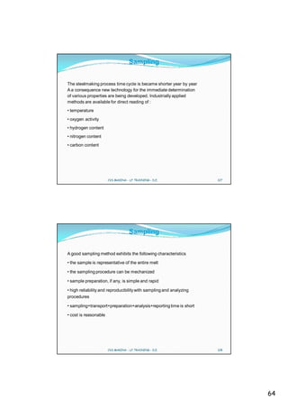
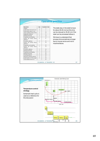
1. The ladle refining furnace (LF) allows for easier secondary metallurgy operations, optimal homogenization, accurate analyses for the continuous casting machine, and improved castability.
2. Key factors for the LF include proper desulfurization, homogenization through porous plugs, maintaining accurate analyses, and achieving cleaner steel through temperature changes and calibrated stirring.
3. Using the LF increases productivity of the overall line from electric arc furnace to continuous caster by reducing refining times and costs in the EAF while providing flexibility through buffering between processes.

![Basic Metallurgy
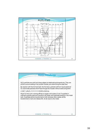
SULPHIDE CAPACITY
One of the most important tasks of refining slag is to absorb and hold S as
sulphide. S
Slag property to hold S is called Sulphide Capacity and it is defined as
Cs = Ks * (%S) * [aO ] / (fS * [%S ] where log Ks = (935/T - 1.375)
Cs can be calculated from (%S) content in the slag, oxygen activity [aO ] in
the steel, sulphur concentration [%S ] in the steel, activity coefficient fS and
the temperature.
The expression for sulphide capacity can be witten as the following form that
is called sulphur partition ratio Ls
Ls = (S%)/[S% ] = Cs * fs / (Ks * aO)
and looking the above formula we understand the factors that promote the
desulphurisation.
CVS MAKINA - LF TRAINING - D.E. 37
Basic Metallurgy
Interaction of Carbon on Sulphur
Activity Coefficient f S
As Function of C Content at 0.03 % S, 1600°C
Activ ity Coefficient fS
5
4
3
2
1
0
0 1 2 3 4 5
C Content, %
CVS MAKINA - LF TRAINING - D.E. 38
19](https://image.slidesharecdn.com/lftraining-100117152304-phpapp01/85/LADLE-FURNACE-AND-SECONDARY-METALLURGY-TRAINING-PREPARED-BY-CVS-MAKINA-19-320.jpg)
![Basic Metallurgy
REFINING REACTIONS.
Refining of steel normally means the removal of one or several elements
from the metal bath.Such refining is brought about by slag metal
reactions,gas-metal reactions or metal bulk reactions.
Refining of the following elements will be discussed: S,H,N,C,O.
In addition fundamental aspects of calcium treatment will be discussed.
Refining of a particular element may be performed by one or several of the
above mentioned reactions.Desulphurisation is a typical slag -metal reaction
whereas deoxidation can be carried out as a metal bulk reaction,slag -metal
reaction ,or even a gas -metal reaction.
CVS MAKINA - LF TRAINING - D.E. 39
Basic metallurgy
Removal of S from steel into the slag is conventionally illustrate by the
reaction
[S] + CaO CaS + [O]
To achieve a good desulphurisation it is first of all necessary that three
fundamental conditions be satisfied.
1. Basic Slag.
2. High Temperature (60-80deg greater than delta T sl).
3. De -oxidation of the bath(aO2 less than 40ppm).
The stirring of the bath and the reactivity of the slag are important to speed
up the formation of Ca Sulphide.
CVS MAKINA - LF TRAINING - D.E. 40
20](https://image.slidesharecdn.com/lftraining-100117152304-phpapp01/85/LADLE-FURNACE-AND-SECONDARY-METALLURGY-TRAINING-PREPARED-BY-CVS-MAKINA-20-320.jpg)
![Basic metallurgy
Removal of S from a metal bath into the slag is conventionally illustrated by the reaction:
S + CaO CaS + O
A basic slag is considered be completely ionised so that we preferably write the desulphurising
reaction:
S + O2- S2- + O
By writing in this manner, we also confirm the fact that not only CaO but also MgO, FeO, Na2O
and other oxides to a varying degree contribute the oxygen ions necessary for the reaction.
We have already defined an expression for the S partition between slag and metal (see section on
sulphide capacity). Now we want to predict the final sulphur content in the metal, however, for
which purpose we must know the specific slag weight, i e kgs of slag per ton of metal, slag
sulphide capacity, the initial concentration of S in the slagbuilders and in the metal and, finally, the
S activity coefficient in the metal.
We assume that the total amount of S remains constant, i e that what has left the metal will be
found in the slag.
CVS MAKINA - LF TRAINING - D.E. 43
Basic metallurgy
It is then possible to derive the expression:
[ %S ]*W ( )
+ %S0 *W slag
[ %S ]=
final
0 steel
W steel +LS *Wslag
where ‘W’ denotes weight.
At this point, we substitute L S for C S * fS / (K S * a O) as described earlier in the discussion about
Sulphide Capacity. That brings us to the expression for final, equilibrium S content in the metal :
%S0 *W steel %S0 *W slag
%Sfinal
W steel CS* fS / KS* a O *W slag
The activity aO can easily be calculated or measured in metals of very varying composition; fS is
likewise easily calculated using Wagner’s formalism; C S can be calculated from slag analysis and
temperature. Weights of metal and slag are already known.
We therefore have all necessary information for calculating the maximum possible extent of
desulphurisation. The figure shows an example with equilibrium sulphur content in the metal as
function of slag V-ratio.
CVS MAKINA - LF TRAINING - D.E. 44
22](https://image.slidesharecdn.com/lftraining-100117152304-phpapp01/85/LADLE-FURNACE-AND-SECONDARY-METALLURGY-TRAINING-PREPARED-BY-CVS-MAKINA-22-320.jpg)
![Basic metallurgy
C alc ulated E v aporation of Elem ents as
F unction of P ressure During Vacuum D egassing
1600 C , 1 % M n, 0.05 % A l, 25 m in utes
Ev aporated A m ount, kg/ton
0 .1 0 Mn
kg/ton ne
0 .0 8 Fe
kg/ton ne
0 .0 6 Al
kg/ton ne
0 .0 4 T o tal
kg/ton ne
0 .0 2
0
0 1 2 3 4 5 6 7 8 9 10
P res s ure, torr
CVS MAKINA - LF TRAINING - D.E. 51
Basic metallurgy
FLUSHING OF DISSOLVED GASES BY GAS PURGING
The fact that the partial pressure of a dissolved gas depends upon its
activity in the metal, and hence upon its concentration, can be taken
of for flushing a dissolved gas out of the metal.
When the metal bath is flushed by an inert gas , for example Argon, the
atoms of the dissolved gas(-es) will recombine at the inert gas bubble
surface and escape into the bubbles.There, the dissolved gas builds up a
partial pressure which approaches equilibrium with the activity of the
dissolved solute. Taking nitrogen for example
2[N ] 2N N2
CVS MAKINA - LF TRAINING - D.E. 52
26](https://image.slidesharecdn.com/lftraining-100117152304-phpapp01/85/LADLE-FURNACE-AND-SECONDARY-METALLURGY-TRAINING-PREPARED-BY-CVS-MAKINA-26-320.jpg)
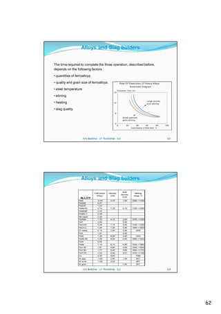
![Heating
Experience shows that an arc power input of up to about 2mw/2 bath area can be
transferred to the metal bath and is tolerable as a dimensioning criterion for the
power supply.
The arc power is not measured but can be calculated.
As a typical value,the arc power is about 84 - 88% of the active power being
supplied by the transformer.
The remaining 12% are lost in resistive heating of the electrical conductors and the
electrodes.
The heating rate as a function of the active power (ie.[Arc power]/0.88) is shown .
CVS MAKINA - LF TRAINING - D.E. 77
Heating
LF H eating Rate vs. Specific Power Input
9
H eating R ate, K/m in
8
7
6
W ate rc. roof
5 °C/m in
Refr. roof
4 °C/m in
3
2
1
0
0 0.05 0 .1 0.15 0.2 0 .2 5
Ac tive Power, MW /tonne
Experience shows that an arc power input of up to about 2 MW/m2 bath area can be transferred to
the metal bath and is tolerable as dimensioning criterion for the power supply.
CVS MAKINA - LF TRAINING - D.E. 78
39](https://image.slidesharecdn.com/lftraining-100117152304-phpapp01/85/LADLE-FURNACE-AND-SECONDARY-METALLURGY-TRAINING-PREPARED-BY-CVS-MAKINA-39-320.jpg)
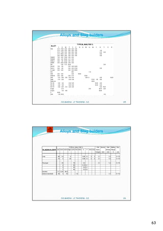
![Heating
Absorbed by the metal.The electrode tip wear is visible as a cavity in
the electrode at the electric arc foot-point.
Fluctuations are provoked by stirring of the metal bath. Gas stirring
provokes a rather unsteady surface whereas inductive stirring ,if
installed provokes a standing w aeve of rather constant profile. The
incidence of metal droplets coming into contact with the electrodes is
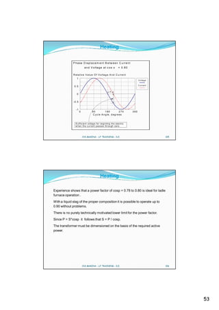
greater with gas stirring than with inductive stirring and the carbon pick-
up is higher.The arc length is obviously of decisive importance for the
carbon pick-up.A study on carbon pick -up as a function of arc length
shows that the arc length for gas stirred ladle furnaces must be about
6.5cm in order that carbon pick-up will not exceed 2.0.To 2.5 ppm
min.The corresponding figure for inductive stirred ladles is rather 5.0
cm.
CVS MAKINA - LF TRAINING - D.E. 83
Heating
C pick-up during heating
(ppm /m in)
30
20
C-pick-up
gas stiring
C-pick-up
10 Ind. stir
0
0 20 40 60 80 100
Arc leng th [m m ]
CVS MAKINA - LF TRAINING - D.E. 84
42](https://image.slidesharecdn.com/lftraining-100117152304-phpapp01/85/LADLE-FURNACE-AND-SECONDARY-METALLURGY-TRAINING-PREPARED-BY-CVS-MAKINA-42-320.jpg)
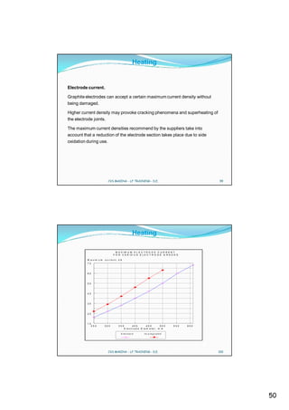
![Heating
Provide premium grade electrodes are being used, electrode consumption is mainly dependent
on steelmaking process conditions. Current level, power on time, oxidizing electrode surface area
and tons per hour are the most important parameters influecing electrode consumption.
Empiriacally developed formula are avalilable to calculate the amount of the two continuous
electrode consumption process.
Typical average oxidation and sublimitation rates are :
2
RsubAC = 0.0135 kg/kA hr - per one electrode tip
Rox = 8 Kg/m2 hr - for the oxidinziing cone of water spray cooled electrodes.
Calculation of continuous graphite consumption (sublimation)
I = current per phase (KA)
2 tpo = power on (hrs)
C tip = Rsub * ( I * tpo) / ( 0.454 * P ) [Kg/ton]
P = productivity (tons/heat)
Calculation of continuous graphite consumption (oxidation)
A = oxidizingelectrode surface area (m2)
ttap = tap to tap (hrs)
side = Rox * ( A * ttap) / P [Kg/ton]
P = productivity (tons/heat)
CVS MAKINA - LF TRAINING - D.E. 87
Heating
Specific electrodes consumption performed at Alpha Steel
Guaranteed values
Guarante electrode consumption 0.012 Kg/kWh
Electrode consumption obtained 0.007 Kg/kWh
Initial weight (Kg) Final weight (Kg) delta W (Kg)
Electrode column 1 908 760 148
Electrode column 2 908 796 112
Electrode column 3 908 780 128
Total weight 1-2-3 2724 2336 388
Total Electric consumption after 18th heats 56800 Kwh
S.E.C obtained after 18th heats 0,007 kg/kWh
Initial weight (Kg) Final weight (Kg) delta W (Kg)
Electrode column 1 908 698 210
Electrode column 2 908 740 168
Electrode column 3 908 735 173
Total weight 1-2-3 2724 2173 551
Total Electric consumption after 28th heats 80700 Kwh
S.E.C obtained after 28th heats 0,007 kg/kWh
Initial weight (Kg) Final weight (Kg) delta W (Kg)
Electrode column 1 908 601 307
Electrode column 2 908 647 261
Electrode column 3 908 641 267
Total weight 1-2-3 2724 1889 835
Total Electric consumption after 39th heats 113800 Kwh
S.E.C obtained after 39th heats 0,007 kg/kWh
CVS MAKINA - LF TRAINING - D.E. 88
44](https://image.slidesharecdn.com/lftraining-100117152304-phpapp01/85/LADLE-FURNACE-AND-SECONDARY-METALLURGY-TRAINING-PREPARED-BY-CVS-MAKINA-44-320.jpg)
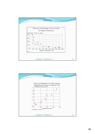
![Heating
There are numerous factors which affect the final nitrogen level
• scrap
•DRI usage
•long arc versus short arc
•tap carbon
•foaming slag practice
•bottom stirring
•tapping
•deoxidation practice
•ferro alloys
CVS MAKINA - LF TRAINING - D.E. 89
Heating
Electric arc heating is potentially cause a substansial pick-up of
atmospheric gases, notably nitrogen
N2 2N 2 [N]
The arc caused the N2 molecule to dissociate to atomic N or ions.
Nitrogen removal is also affected by surface actives elements O
and S.
CVS MAKINA - LF TRAINING - D.E. 90
45](https://image.slidesharecdn.com/lftraining-100117152304-phpapp01/85/LADLE-FURNACE-AND-SECONDARY-METALLURGY-TRAINING-PREPARED-BY-CVS-MAKINA-45-320.jpg)
![Stirring
INDUCTIVE STIRRING.
Inductive stirring of a metal bath works as an electric motor in which the
stirrer itself is the stator and the metal bath the rotor.
A current of up to 1350A in the inductive stirrer generates a very strong
travelling electromagnetic field.
The metal velocity pattern is more uniform with inductive stirring than with
gas stirring which ensures rapid homogenisation of the temperature and the
analysis.
The lack of ripples on the metal surface minimises carbon pickup during arc
heating but gives poor mixing between slag and metal and therefore poor
desulphurisation.
CVS MAKINA - LF TRAINING - D.E. 117
Stirring
CHARACTERISATION OF STIRRING.
This phenomena is expressed mathematically according to (sundberg).as:
= 371* Qgas *Tl * [( 1-Ta/Tl) + in (P 1/P2)] W/ton
where Qgas = gas flowrate Nm3/sec.
G as S tirrin g P o w er A s F u n ctio n
Tl =metal temperature K. O f M e ta l B at h H e ig ht
Ta = gas entrance temperature K B ath H eig ht, m
P1 =total pressure at ladle bottom
P2 = pressure above bath surface 2 .5
2
1 .5
1
0 .5
0
0 10 20 30 40
S tirring P o w er, W /to nn e
G a s flo w r a te 1 .5 N l /m in,to n , 1 6 0 0 °C
CVS MAKINA - LF TRAINING - D.E. 118
59](https://image.slidesharecdn.com/lftraining-100117152304-phpapp01/85/LADLE-FURNACE-AND-SECONDARY-METALLURGY-TRAINING-PREPARED-BY-CVS-MAKINA-59-320.jpg)