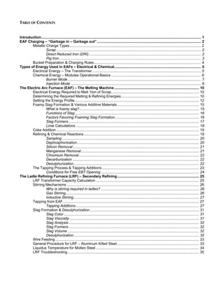
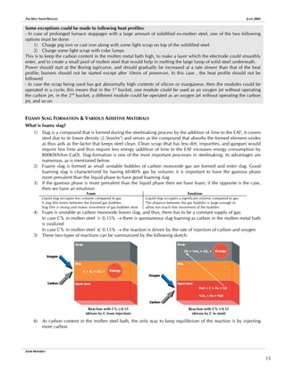
This document provides an overview of the melt shop production process at Al Ezz Steel Rebars Company. It describes the key steps in melting steel in an Electric Arc Furnace (EAF) and refining it in a Ladle Refining Furnace (LRF). The document outlines the types of metallic inputs used in the EAF like scrap, direct reduced iron, and pig iron. It also explains the electrical and chemical energy inputs used for melting. Key phases of EAF operation discussed include charging, melting, slag formation, refining reactions, and tapping. Processes in the LRF covered include stirring mechanisms, tapping additions, slag formation, desulphurization, and general operating procedures. The goal of the document
![THE MELT SHOP PROCESS JUNE 2005
EAF CHARGING – “GARBAGE IN – GARBAGE OUT”
The Electric Arc Furnace charge is one of the most important determining elements for the efficiency of the EAF
process. The variables of the charging process are many, and they are mostly dependant on the steel grade that is to
be produced.
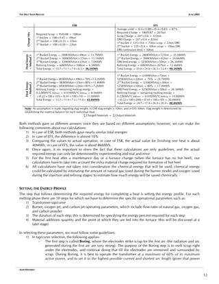
METALLIC CHARGE TYPES
Scrap: this is the most common metallic charge that is being used in modern electric arc furnaces. EAFs were initially
made to produce steel from scrap. This was based on two important factors: a] the idea of recycling was initially
attractive to many people, and was thought of as environmentally friendly, and b] scrap was thought of as a cheap raw
material for such an industry. As the industry progressed, these ideas started changing; the use of oxygen increased
the amount of off-gases produced by EAFs, and the price of scrap started sky-rocketing as demand for such a
commodity increased by time. However, scrap still remains the most common metallic charge for modern day EAFs.
Scrap requires 330-390KWh/ton to melt. This range is dependent on furnace efficiencies, which varies from one Melt
Shop to the other.
Certain characteristics should be considered in order to select the proper type of scrap:
Density: scrap density varies between light scrap (<0.5ton/m3
) and heavy scrap (1ton/m3
). Both extremes have their
own advantages. Light scrap is melted easily, and is more suited for furnaces equipped with burners; however, the use
of light scrap might require a greater number of bucket charges, thus leading to more power-off time, and more heat
losses per heat. Heavy scrap would avoid the problem of the increased number of bucket charges; however, it would
require greater melting energy and lead to more refractory and electrode consumption. The ideal scrap density for
EAFs would be 0.7ton/m3
, as this would strike a balance between the benefits of both light and heavy scrap.
Size: the maximum allowable dimension (this applies to length, width, or diameter) of a piece of scrap is
150cm×50cm×50cm. Pieces of larger sizes could have harmful effects on the furnace water-cooled panels (arcing)
and would require greater melting time.
Output Potential: non-metallic materials should be avoided as much as possible; these materials have no use for the
steelmaking process, and they lead to a decrease in yield. Naturally, their presence in large quantities in scrap is
unavoidable; however, during the scrap segregation process, any material of such kind should be removed.
Quality: scrap quality is categorized based on several factors including yield and the presence of undesirable
elements. For example, the C-categorization indicates the copper content in scrap:
C1: 0.10%<Cu <0.14%
C2: 0.15%<Cu <0.25%
C3: 0.26%<Cu <0.35%
C4: 0.36%<Cu <0.48%
Copper is one of the important elements that are always monitored in the final products
chemical analysis. If copper content exceeds 0.50%, this may lead to surface roughness
and other surface defects. In some steel grades, the required copper content is as low as
0.13%, which is usually hard to achieve using scrap solely
Other elements affecting the quality of scrap include phosphorous and sulfur; the lower the content of these elements,
the greater the quality of scrap.
Valuable Material Content: another term for this phrase is scrap “yield”. This could have several effects:
a] Assuming that two scrap types are available, type A ($80/ton, 75% yield) and type B ($90/ton, 90% yield).
The price per valuable material of type A would be $107/ton, and that of type B would be $100/ton. Clearly,
the more expensive scrap with higher yield, turned out to be cheaper on a per valuable material basis
b] Yield could also affect the melting process and could possibly lead to a greater number of bucket charges.
c] The presence of alloying elements in the metallic charge should be avoided unless these elements are
desired in the final product. Undesirable alloying elements would lead to a greater price of scrap per ton, and
would require additional effort in the production process to remove these elements to achieve the target
chemical analysis.
Direct Reduced Iron (DRI): DRI is also known as sponge iron. It is the most suitable type
of metallic charge for the production of clean steel due to its low tramp elements and
impurities content. However, DRI requires 500-600KWh/ton to melt; this is higher than
that required by scrap, and thus there is a trade-off between the cleanliness of the
products and the energy requirement.
Chemical Composition of DRI
Metallization 92-95%
Carbon 1-3%
SiO2 1-3%
Al2O3 0.5-3%
CaO 0.1-2%
MgO 0.1-1%
Chemical Characteristics
- The direct reduction process removes most of the oxygen and sulfur from the
AMIR MISHRIKY
2](https://image.slidesharecdn.com/88776543-the-melt-shop-process-211026192259/85/88776543-the-melt-shop-process-4-320.jpg)
![THE MELT SHOP PROCESS JUNE 2005
iron ore, but leaves all of the impurities and gangue content
- Metallization (the ratio of metallic iron to total iron, including FeO) depends on the type of process used to
produce DRI; two processes are used to produce DRI, the Batch process, which gives a range of 85-90% and
the Rotary Shaft process, which gives range of 90-95%
- DRI contains no tramp elements (scrap contains elements such as Cu, Zn, Pb, Sn, As, Cr, Ni, and Mo); it only
contains traces of sulfur and phosphorous.
Physical Characteristics
DRI PELLETS
- The best diameter of DRI pellets for furnace charging is 6-16mm (diameters
less than 3mm are called DRI fines, and not pellets).
- Apparent density: 2-3ton/m3
- Bulk density (accounts for air gaps): 1.6-1.9 ton/m3
Furnace Charging: DRI could either be charged through the scrap bucket (bulk
charging) or continuously fed into the EAF using belt conveyors. If the charge amount
is less than 20%, bulk charging could be used. If the charge is greater than 20%, then
a mix of bulk charging and continuous feeding could be used, or continuous feeding
only.
- Bulk charging is not the most preferred type of DRI input into the furnace, and has some rules that should be
strictly followed:
a] The mass of DRI should not exceed 30% of the total mass of the scrap bucket charge; if the
content of a single bucket exceeds that level, then there would be a risk of DRI buildup on the
furnace side walls
b] DRI should be charged in between the scrap layers in the bucket; lumps of DRI in the bucket
should be avoided
- Continuous feeding is the best type of DRI charging, and it also has some rules that should be followed:
a] DRI is typically fed through the fourth hole in the EAF roof
b] The additive system should be designed such that it allows sufficient free fall for DRI to penetrate
the slag layer
c] DRI feeding should start when the temperature of the molten metal bath reached 1580o
C and
when all scrap inside the furnace has melted
d] Feeding should start at one third of the maximum feed-rate (7-10Kg/min.MW)
e] Lime should be fed simultaneously with DRI (care should be taken when doing that as excessive
lime feed-rate could cause an overflow from the vibrating hopper feeding the furnace – this is a
function of individual furnaces, and the best practice is only established by experimenting)
f] The electric power should correspond to 25-30Kg/min.MW; for example, if a feed-rate of
3000Kg/min is used, then the electric power supplied during charging should be 100-120MW. If too
low power is used (or too high feed-rate), then there is the risk of forming an Iceberg. If the opposite
occurs, then there is risk of molten metal bath over-temperature
g] The best position for DRI to be fed (as is the case with all other additive materials that are charged
through the fourth hole in the EAF roof) is in between the three electrodes closest to the center of the
electrode pitch circle
h] A short arc (high current/low voltage) should be used during DRI feeding
Precautions: DRI should be handled with utmost care. It is a highly reactive substance that could easily catch fire; it
also oxidizes at 210-275o
C, and is reactive in the presence of water. Improper handling could lead to serious damage
to components of the materials handling system, such as the belt conveyors, and also leads to loss of yield. Most of
the materials handling systems that deal with DRI are equipped with fire fighting systems.
Pig Iron the advantages of using pig iron include: a] it is a bulky material that uses up low
volume in the furnace and scrap buckets, b] the high carbon, silicon, manganese, and
phosphorous will oxidize in the furnace in exothermic reactions that aid in the melting
process and make it quicker, and c] it requires 280KWh/ton for complete melting, which is
lower than that required for DRI or scrap. The only disadvantage if using pig iron is that it
contains impurities which might prolong the refining time.
Chemical Composition
of Pig Iron
Carbon 3-5%
Silicon ≤2%
Manganese ≤1%
Phosphorous ≤0.12%
Sulfur ≤0.04%
AMIR MISHRIKY
3](https://image.slidesharecdn.com/88776543-the-melt-shop-process-211026192259/85/88776543-the-melt-shop-process-5-320.jpg)
![THE MELT SHOP PROCESS JUNE 2005
BUCKET PREPARATION & CHARGING RULES
Handling of the charge material, scrap segregation, and scrap bucket charging are among
the most important factors for success of Melt Shops. These operations are what guarantees
safe and smooth running of EAFs. The following rules should always be followed when
preparing and charging buckets:
- Exclude: a] dangerous materials (explosives and closed containers) as they could
possibly lead to explosions, b] wet materials (oil or water), c] inert/insulating
materials (concrete blocks, wood, rubber, and others) as they cause lower yield,
and may lead to electrode breakages
- Copper and tin should not be charged at all inside the EAF. These elements
cannot be removed from the molten metal bath once they enter. Once charged,
the content of these elements can only be decreased by dilution; DRI is best utilized for that purpose. Both
these elements cause week points in the steel matrix, which later on become the initiation point of surface
defects and cracks during the rolling process.
- Layering should be executed as shown in the sketch. Some light scrap (10%
of the charge mass) should be at the bottom of the charge to protect the
hearth refractory. This should be followed by the heavy/medium scrap and
any DRI layers, which form the bulk of the charge. A final layer of light scrap
is needed at the top of the charge; this layer is required for the following
reasons:
a] Protection of the roof panels from the first arc
b] Allow for easy scrap penetration
c] It will easily melt and spread to the rest of the scrap and help in
the melting process
d] Avoid any potential electrode breakages with the first arc strike
Medium scrap ~0.55ton/m3
Light scrap for easy/smooth arc
try and protection of roof pane
from the first arc radiation
en ls
Heavy scrap ~0.65ton/m3
(maximum of 5ton of large sized
pieces 1.5m×0.5m×0.5m)
Lightscraptoprotectrefractory,
lesssplashingofhotheel,and
helpsmeltingofheavyscrap
- With 2-bucket charge heats, the 1st
bucket should contain 55-65% of the
charge, and the remaining in the 2nd
bucket. In case of 3-bucket charge heats,
the content should be close to 45%-35%-20%.
- Large pieces of scrap should only be charged in the 1st
bucket as they require longer melting time than others.
- Scrap bucket opening over the EAF is also a critical process. Improper charging practices will cause electrode
breakages, prolonged melting time, molten metal splashing (which could cause damage to furnace
components such as water-cooled cables and any hoses in the furnace surround), and scrap leveling. For that
reason, two important rules must be followed: a] the bucket should be as close to
the shell, and b] opening of the clamshells should be done as quick as possible to
preserve the scrap layering
- Some of the bucket design features should always be monitored; these features
include:
a] Ratio of bucket volume to EAF shell volume; this should not exceed
85% in order to minimize scrap leveling
b] Ratio of bucket diameter to EAF shell diameter; this ratio should not
exceed 90% in order to prevent scrap from falling outside the EAF shell
while charging
The following are examples of these ratios in some furnaces:
Ezz Steel Rebars (ESR) Ezz Flat Steel (EFS) Suez Steel
Bucket Volume [m3
] 87 165 79
EAF Shell Volume [m3
] 92 202 120
Bucket/Shell Volume Ratio 95% 82% 66%
The worst design is that of ESR, and it causes the most scrap leveling delays. In some cases, the operators are
forced to resort to 4-bucket charge heats
- The number of scrap bucket charges should be minimized is order to decrease EAF power-off time, and
decrease heat losses from the EAF while the roof is open
AMIR MISHRIKY
4](https://image.slidesharecdn.com/88776543-the-melt-shop-process-211026192259/85/88776543-the-melt-shop-process-6-320.jpg)
![THE MELT SHOP PROCESS JUNE 2005
TYPES OF ENERGY USED IN EAFS – ELECTRICAL & CHEMICAL
ELECTRICAL ENERGY – THE TRANSFORMER
The main type of energy used in an EAF is electrical energy. In order to understand the underlying principles of steel
melting, some simple background information in electricity is required. This is not meant to be an extensive account
of electrical engineering, but only basic information that might be useful.
The electrical power supply coming into the furnace is of the 3-phase type. 3-Phase
electical power could be characterized by the sketch shown; there are three types of
power: 1) apparent power (which is delivered from the main power line), 2) active
power (which is the final power input that is used by the application, the EAF in our
case), and 3) reactive power (which includes the losses of power, or the unused power).
A relation exists between the three types of power and its as follows:
PApparent
2
= PActive
2
+ PReactive
2
The degree to which power is lost is represented by what we call the Power Factor. The
Power Factor is cosφ (where φ is the angle represented in the sketch on the right. Clearly,
the greater the angle φ, while everything else held constant, the greater the Active Power relative to the Reactive
Power. Typically, it is desired to have EAFs operating at a Power Factor in the range of 0.75-0.85.
φ
Apparent
Power (PAP)
Reactive
Power
(P
R
)
Active Power (PAC)
Power is delivered to the EAF by passing through a series of stages:
VS
NS
Np
Vp
1) Power is taken from the primary supply (typically the main power lines); this
power is characterized by a high voltage and a low current (power losses are to
a great extent dependant on current, and thus it is preferable to transfer power
at high voltage rather than high current to minimize these losses)
2) Primary power is delivered to a transformer, which is equipped with a tap
changer. The function of the tap changer is to enable delivery of variable power
to the EAF. A tap changer has a variable resistance on the primary side, and a
fixed resistance on the secondary side, and this is what enables the control of
the secondary voltage and current.
3) Power is then delivered to the EAF electrodes. There is a slight drop in power
between the secondary side and the electrodes, and this is in the form of heat
losses in bus bars and power cables.
The Basic Idea of a Tap Changer
NP.VP=NS.VS
N: Number of coil wounds
V: Voltage
S: Secondary side
P: Primary Side
Secondary Side
Transformer EAF Electrodes
Primary Side
Transformers are supplied with a transformer table that shows the characteristics of
each tap with its corresponding curve. A sketch of a transformer table is shown
below. Each cell in the transformer table provides information such as active power,
the arc power (arc power = active power – losses in secondary side), power factor,
arc current, and others. This information is helpful in setting up the power profile for
a furnace. The main characteristics of the transformer table are as follows
(applicable to transformers in ESR and EFS, but might be different with other
transformers depending on the supplier):
Example of a Transformer Table
Tap/Curve 6 5 4 3 2 1
1
2
3
4
.
.
.
.
19
20
21
Increasing
Power
More Voltage
& Lower Current
Boring and refining
Melting
1) As higher taps are used, the active power increases
2) For the same tap, a low curve has more voltage and lower current relative
to a high curve
The following are some important relations that should be considered when setting a heat profile:
1) Higher voltages mean greater Arc Length (long arc), which has three effects: a] lower electrode consumption,
b] the ability to melt scrap that is away from the electrodes and close to the furnace walls (thus preventing the
accumulation of unmelted scrap and formation of skulls on the furnace walls), and c] lower electrode
consumption
2) Arc Length [mm] = Arc Voltage [V] – 35
AMIR MISHRIKY
5](https://image.slidesharecdn.com/88776543-the-melt-shop-process-211026192259/85/88776543-the-melt-shop-process-7-320.jpg)
![THE MELT SHOP PROCESS JUNE 2005
3) Although long arcs give many advantages, they may also be a disadvantage if excessively large in length. As
previously mentioned, a long arc has the ability to melt scrap near the furnace walls; if this is accompanied
by long pieces of scrap, then some damage in the form of arcing may occur to the EAF water-cooled panels,
thus leading to possible delays
4) The greater the arc current the greater the ability of the arc to melt scrap under the electrodes; however, this
is accompanied by greater electrode consumption
5) Radiation Index (IR) = VARC
2
.IARC/d2
, where d is the smallest distance from the center of the electrode to the
furnace walls. The Radiation Index (IR) is a relative measure of the
degree of wear that could be caused to the furnace refractory; the higher
the IR the greater the refractory wear rate. This equation also shows us
the factors affecting wear rate:
a] Refractory wear rate is directly proportional to arc voltage
and arc current; however, the influence of arc voltage is much
greater (it is squared)
b] The greater the distance of the electrode from the furnace
side wall the lower the refractory wear rate; this could also be a
logical assumption Current
effect
Voltage
effect
An increased voltage
has a heating effect in a
direction perpendicular
to the electrode
An increased current
has a heating effect in a
direction under the
electrode
The following table summarizes all of the above-mentioned relations:
Long Arc Short Arc
Low electrode consumption High electrode consumption
Melts scrap away from the electrode Melts scrap under the electrode
Will cause greater refractory wear rate Will cause less refractory wear rate
Might be dangerous for water-cooled
panels if arc is excessively long
Provides adequate protection for
water-cooled panels
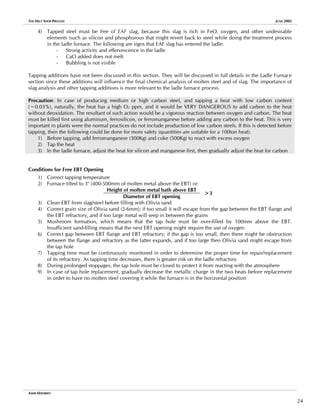
CHEMICAL ENERGY – MODULES OPERATIONAL BASICS
The following drawing would help explain the operation of the modules:
AMIR MISHRIKY
6](https://image.slidesharecdn.com/88776543-the-melt-shop-process-211026192259/85/88776543-the-melt-shop-process-8-320.jpg)
![THE MELT SHOP PROCESS JUNE 2005
Carbon Jet
Oxygen Jet
31-35o
41-45o
Cooling water inlet
Cooling water outlet
Natural gas line
Oxygen line
Carbon line
Natural gas line
Cooling water outlet
Cooling water inlet
Burner Mode
Function: The main function of burners is to melt scrap in front of the oxygen and carbon injectors in order to make
space for oxygen-injection and prevent any possible oxygen flashbacks that may cause damage to the jets or water-
cooled panels. Burners are only useful for melting scrap, and should be stopped once scrap in front of them has
melted; further operation of the burners beyond that point would be considered a loss of energy. Burners are more
suitable with light scrap than with heavy scrap; light scrap is more penetrable than heavy scrap, which requires more
burner time.
The module burner mode makes use of mixing methane gas (natural gas – CH4) with oxygen gas (O2) in the following
reaction:
CH4 + 2O2 → CO2 + 2H2O + 8800Kcal/Nm3
CH4
The following are some basic rules for the operation of burners:
1) Burner operation time per charge of scrap bucket could be calculated using the following formula:
X[KWh/ton] × Bucket Charge [ton] × 60
Burner time [min]=
Average Transformer Power [MW] × 1000
Where:
- X=150KWh/ton for the 1st
bucket, 140KWh/ton for the 2nd
bucket, and 130KWh/ton for the 3rd
bucket
- Bucket Charge=Weight of Scrap + 0.5×Weight of DRI
The burner time determined by this equation only serves as a guide; the optimum burner time is a function of
other factors, including the type of scrap used. Only through experimenting may one be able to determine
the best burner time that is suited for the operational conditions available in a particular plant.
2) Excessive burner time is considered a waste of energy, and too low of a burner time exposes the furnace
components to great danger
3) During operation of the modules in the burner mode, lime, dolomite, or any other additive material cannot
be charged into the furnace
4) Burner power saving could be calculated using the following formula:
CH4 Consumption [Nm3
] ×8800Kcal/Nm3
CH4
Power Saving [MWh]=
1000 × 860Kcal/KW
5) The optimum CH4:O2 ratio is 1:2, in Nm3
. This ratio could be obtained by simply looking at the chemically
balanced CH4/O2 equation, which is mentioned above, and is also based on an efficiency of 100%. In actual
operation, the ration starts by 1:1.8, and is gradually increased to 1:2.1, 1:2.4, 1:2.7, and 1:3.0. The staged
increase in the oxygen ratio is to prevent any possible oxygen flashbacks into the module jet or water-cooled
panels. In case of operation with heavy scrap, high ratios should be avoided as heavy scrap would require
more time to melt.
6) During continuous operation, the burners should only be operated after 2min of power-on time on each
bucket, or when the temperature inside the furnace reaches 800o
C; this will prevent the formation of any
natural gas pockets inside the furnace, and eliminate the possibility of any explosions inside the furnace
7) In case of prolonged EAF stoppages, the burners may not be operated except for after 10min of power-on
time, for the same reason as that mentioned in the previous point
8) In case of operation with 100% DRI or during DRI continuous feeding, burners should not be used at all
AMIR MISHRIKY
7](https://image.slidesharecdn.com/88776543-the-melt-shop-process-211026192259/85/88776543-the-melt-shop-process-9-320.jpg)
![THE MELT SHOP PROCESS JUNE 2005
Injection Mode
Function: The injection mode follows the burner mode in the order of operation. The injection mode serves the
following functions:
1) Similar to a cutting torch, the injected oxygen will cut into scrap and aid the melting process
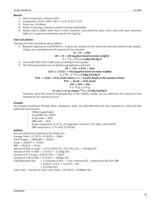
2) The chemical reactions between carbon and oxygen are exothermic
C + ½O → CO + 2.75KWh/Nm3
O2
CO + ½O → CO2 + 7KWh/Nm3
O2
C + O2 → CO2 + 4.88KWh/Nm3
O2
3) Formation of carbon monoxide gas (CO) helps in the formation of foamy slag (the advantages of such will be
discussed in later sections)
4) In general, oxygen injection can be used solely to oxidize undesirable elements in molten steel; this is
achieved during the refining stage
The following are some basic rules for the operation of injectors:
1) The above-mentioned values for energy generation of the module chemical reactions assume 100% yield of
all injected carbon and oxygen and 100% efficiency of the reactions; in real life, this is not true, and it was
determined experimentally that only 3KW/Nm3
of energy are generated. This low efficiency is a result of the
fact that not all oxygen and carbon injected in the EAF react together. Oxygen and carbon uses in the EAF are
summarized in the following table:
Oxygen Carbon
Reacts with carbon
Burns other elements in steel
Could be lost by suction with the fumes
Reacts with oxygen
Absorbed into steel (dissolves)
Could be lost by suction with the fumes
2) Energy provided from oxygen and carbon injection could be determined by the following formula:
O2 Consumption in injection mode [Nm3
] ×3KW/Nm3
O2
Energy from Oxygen Injection [MWh]=
1000
3) The optimum C[Kg/min]:O2[Nm3
/min] ratio is 0.6:1. This was determined by analyzing the chemical balance
of the complete oxidation of carbon C + O2 → CO2 requires:
12Kg Carbon + 22.4Nm3
Oxygen
Dividing both figures by 22.4 … 0.54Kg Carbon + 1Nm3
Oxygen
Assuming carbon yield is 90% …
Required Carbon = 0.54/0.9 = 0.6Kg/Nm3
O2
4) In the refining stage, the decarburation process is governed by the following empirical relations:
O2 Flow rate [Nm3
/h] = (1.2~1.5) × n × t × 6
n: decraburation rate [0.01% C/min]
t: furnace capacity [ton]
6 × Ceq × t [ton]
If Ceq>15 … Tdecarb[min]=
Q [O2 Nm3
]
Where Ceq[0.01%] = C[0.01%] + 0.8Si[0.01%] + 0.5Mg[0.01%] + 0.2Mn[0.01%] + 9P[0.001%]
5) The important operational parameters that must be considered for proper operation of modules are:
- Module jet angles should be properly adjusted; typically, the oxygen jet is adjusted to 41-45o
and the
carbon jet is adjusted to 31-35o
. With regards to the angle of the oxygen jet, if it is significantly
different than that specified, then this could lead to adverse effects:
If angle > 45o
→ excessive molten metal penetration that could damage the hearth refractory
If angle < 41o
→ insufficient molten metal penetration that would lead to molten metal splashing
(this would later on cause damage to the shell and roof panels)
- The distance from the molten metal bath is of utmost importance; as the distance increases, the
oxygen jet dispersion increases and the flow becomes irregular. Turbulence of the oxygen jet flow
will lead to improper penetration of oxygen into the molten metal bath:
If distance is short → excessive molten metal penetration
If distance is long → insufficient molten metal penetration that would lead to molten metal splashing
- The oxygen outlet pressure from the oxygen jet should be ~11bar; the suitable nozzle diameter for
the oxygen jet is governed by the following formula:
822 × e × P1 × do
2
Q=
√T1
AMIR MISHRIKY
8](https://image.slidesharecdn.com/88776543-the-melt-shop-process-211026192259/85/88776543-the-melt-shop-process-10-320.jpg)
![THE MELT SHOP PROCESS JUNE 2005
Where:
Q: O2 flow rate [Nm3
/h]
e: restricting coefficient
P1: absolute pressure upstream the nozzle [bar]
do: nozzle diameter [cm]
T1: absolute temperature upstream the nozzle [o
K]
This is one of the most important parameters for proper oxygen injection and good penetration of
oxygen through the molten steel. Given the required flow-rate of oxygen per oxygen jet, the inlet
oxygen pressure and temperature, and a restricting coefficient (a measure of flow efficiency) in the
range 0.85-0.95, the nozzle diameter could be calculated
Similar to the two previous parameters:
If pressure is too high → excessive molten metal penetration
If pressure is low → insufficient molten metal penetration that would lead to molten metal splashing
- Carbon quality should conform to the following specifications:
a] Humidity<1%
b] Ashes ≤ 13%
c] Volatilities ≤ 1.5%
d] Sulfur ≤ 0.8%
e] Carbon ≥ 85%
f] Thermal capacity 6800Kcal/Kg
g] Diameter/grain size 1-3mm
- Proper carbon/oxygen jet positioning is one other factor that is essential for achieving a proper
reaction between the injected carbon and oxygen. This could be achieved by:
a] There must be good mixing between carbon and oxygen; the best point of intersection of
the carbon and oxygen jets is in the slag layer to guarantee that energy is absorbed into the
molten metal bath. If the reaction occurs outside the molten metal bath or the slag layer,
then energy would be lost to the outside atmosphere of the EAF
b] Modules should be well spread around the EAF shell in order to guarantee a good
distribution of foamy slag
c] Modules should be placed in position where there is least probability of lost injected
components; for example, placing the modules below the fumes elbow would increase the
probability of losing injected carbon into the fumes suction system
Failure to follow these rules would lead to
inefficient chemical reactions, lost material to the
fumes system, and formation of skulls inside the
furnace, as seen in the picture on the right. These
skulls that form are a mixture of accumulated
carbon fines and scrap. The carbon content in
these huge pieces is quite high, and if it breaks
off the furnace side walls, it could lead to a heavy
reaction, which is dangerous; if it breaks off while
the EAF is tilted during tapping, there will be a
sudden increase of carbon content of the molten
metal bath, and this could lead to a heat that is
out of proper chemical composition.
A mixture of accumulated slag/carbon/scrap due to
improper setting of the carbon jet
AMIR MISHRIKY
9](https://image.slidesharecdn.com/88776543-the-melt-shop-process-211026192259/85/88776543-the-melt-shop-process-11-320.jpg)
![THE MELT SHOP PROCESS JUNE 2005
THE ELECTRIC ARC FURNACE (EAF) – THE MELTING MACHINE
The EAF process could be divided into two mains steps, the melting step in
which the metallic charge is completely melted up to ~1536o
C, and the
refining step, in which the molten steel is cleaned from all undesirable
elements, and is further heated to ~1640o
C. The heat should be tapped from
the EAF at a chemical composition that is within the allowable chemical
composition range. The EAF makes use of two kinds of energy: electrical
energy supplied by the graphite electrodes, and chemical energy from the
burner and oxy/carbon systems. The current trend in modern EAFs is that
there has been an increased degree of reliance on chemical energy.
The following sections are divided in a sequential manner that will take us
through the melting and refining steps in great detail, and also make mention
of the basic rules for setting the heating profile at each individual step. We
shall first start by calculating the theoretical energy required for melting a ton
of scrap.
ELECTRICAL ENERGY REQUIRED TO MELT 1TON OF SCRAP
To convert any substance from the solid phase to the liquid phase, it passes through two stages:
1) Increasing the temperature from Tinitial to Tmelt; the energy, Q, consumed during this process is measured by
the equation Q = m.Cp.∆T, where m is the mass of the substance being heated in Kg, Cp is the specific heat
capacity of the material (energy required to raise the temperature of 1Kg by 1o
C), and ∆T is the change in
temperature
2) Energy is required to change the form of the substance from solid to liquid, and this energy is called Latent
Heat
For scrap:
Cp = 140Kcal/o
C.ton
Latent Heat = 60000Kcal
Tinitial=25o
C, Tmelt=1536o
C
∴ Total Energy Required = [1×140×(1536-25)] + 60000 = 271540Kcal/ton ≅ 316KWh/ton
In the refining stage, the following figures could be found helpful:
- 0.22KWh/ton are required to raise the temperature of 1ton of molten steel by 1o
C
- 0.41KWh/ton are required to raise the temperature of 1ton of slag by 1o
C
DETERMINING THE REQUIRED MELTING & REFINING ENERGIES
The sequence of operation of the EAF goes through the stage of melting and refining. In melting, scrap is melted up to
the stage at which the next metallic charge could be placed in the furnace; this does not require complete melting of
the metallic charge. In refining, the metallic charge is completely melted, and all the undesirable materials are
removed; the objective of the refining stage is to superheat the melt and guarantee that all the elements in the metal
bath are within or below their allowable range. In this part of the manual, we shall examine the melting rules, and
refining will be examined in a later part.
Several guidelines are available for establishing a melting practice:
- The first guideline is based on the following:
a] 1st
bucket melted up to 280KWh/ton
b] 2nd
bucket melted up to 300KWh/ton
c] 3rd
bucket (if available) melted up to 320KWh/ton
d] The refining stage requires 60KWh/ton
- The second guideline is based on the following:
a] 1st
bucket melted up to 70% of the assumed melting energy
b] 2nd
bucket melted up to 80% of the assumed melting energy
AMIR MISHRIKY
10](https://image.slidesharecdn.com/88776543-the-melt-shop-process-211026192259/85/88776543-the-melt-shop-process-12-320.jpg)
![THE MELT SHOP PROCESS JUNE 2005
c] 3rd
bucket melted up to 85% of the assumed melting energy
d] The remaining energy and that required for refining should then be applied in the refining stage
In the previous section, we determined he required energy to melt 1ton of scrap as
316KWh/ton; this is the theoretical energy, and we must put in mind that the actual
energy is greater than this figure due to the various heat losses in the EAF. There is
no specific figure that is used in calculations; each individual furnace has its own
figure depending on its working conditions, and this is determined through heat
balance calculations. Normally, the figure could be anywhere between
330KWh/ton to 400KWh/ton. For example, in ESR, the heat profile is based on
395KWh/ton, and in EFS on 330KWh/ton. Differences such as that must have some
kind of reasoning; in case of ESR and EFS, this difference is attributable to the
following:
EAF Shell with Bottom Stirring
1) The EFS furnace is equipped with bottom stirring, which helps maintain molten metal bath temperature
homogeneity
2) In EFS, a stable amount of hot heel, reaching up to 30ton, could be maintained throughout operation; in ESR,
this is not facilitated as the shell is undersized
As previously mentioned, and as is the case with most of the calculations in this manual, these instructions only serve
as guidelines. The actual melting profile could be completely different from the actual required energy. These
instructions serve as a starting point, and then the proper profile would be established by trial and error, and
experimenting.
With regards to DRI, we have already mentioned the melting requirements, but we shall summarize them again here:
1) DRI requires an energy in the range to 500-600KWh/ton
2) DRI is only charged when the molten metal bath temperature has reached 1580o
C
3) DRI feed-rate and the corresponding transformer tap should abide to the relation:
25-30Kg/min.MW
For example; if the used feed-rate shall be 3000Kg/min, then the proper power used for DRI should be in the
range of 100-120MW
Furthermore, if we reverse the logic of this equation:
In case of 100MW → 3ton are fed in 1min, and 1.667MWh are consumed → 1667KWh/3ton = 555KWh/ton
4) The tap/curve selection should guarantee use of the shortest arc possible (and highest current) corresponding
to the selected transformer power.
We shall now take two real life examples from ESR and EFS and try to determine the required charge mix and
calculate the required melting energy using the two approaches described above:
ESR EFS
95 180
Number of bucket charges 3 2
Scrap/DRI mix 100% scrap 60% scrap, 40% DRI
Transformer power [MVA] 85 133
Chemical Energy:
Modules and Burners
3 modules (carbon/oxygen jets) with maximum
oxygen flow of 2350 Nm3
/h, and maximum
natural gas flow rate of 390Nm3
/h
2 modules (carbon/oxygen jets) with maximum
oxygen flow of 1900 Nm3
/h, 2 oxygen
injectors (one with maximum oxygen flow of
1900 and another with maximum oxygen flow
of 1600 Nm3
/h), and maximum natural gas
flow rate of 400Nm3
/h, and 1 burner
Maximum DRI flow-rate [ton/min] 1.5 4.5
Steel grade required Medium carbon steel Low carbon steel
Bottom Stirring No Yes
We shall now calculate the charge mix and the energy required for complete melting assuming the following:
- Scrap yield = 88%
- DRI yield = 85%
- Energy required to melt Scrap = 385KWh/ton for ESR, and 330KWh/ton for EFS
- Energy required to melt DRI = 525KWh/ton
- Tapping temperature = 1640o
C
AMIR MISHRIKY
11](https://image.slidesharecdn.com/88776543-the-melt-shop-process-211026192259/85/88776543-the-melt-shop-process-13-320.jpg)
![THE MELT SHOP PROCESS JUNE 2005
setting). The underlying reason is that we would like to minimize any possible damage to the water-
cooled roof panels that might be cause by reflection of an arc towards the panels. Failure to comply
with these settings would result in great damage to the water-cooled roof panel. The duration of the
Boring step should sufficient enough such that after it finishes, the electrodes are submerged in scrap.
- The next step is called Melting, where scrap is heated till the energy that was determined by the
calculation specific for our phase (melting 1st
bucket, melting 2nd
bucket, melting 3rd
bucket, or
refining). In melting, it is required to increase the operating power up to about 100% of the
maximum transformer active power, and using the longest arc possible. The underlying reason is that
we would like to reach the required melting degree in the minimum time possible, and we would
like to use a long arc in order to melt the charge that is close to the furnace side walls (this acts as a
prevention for electrodes, since melting scrap beneath the electrode might lead to having a piece of
scrap falling from the side walls into the middle of the furnace and causing electrode breakages).
Also, a long arc would guarantee minimum electrode consumption; however, a trade-off exists
between the benefits of using a long arc, which were just mentioned, and the disadvantages, which
are the potential damages to water-cooled panels and higher refractory consumption.
- The last two steps of the phase should utilize a gradually decreasing arc length such that we
guarantee homogeneous melting of the metallic charge in the region close to the furnace side walls
and that in the center of the furnace.
- In DRI Feeding, we set the transformer to 25-30Kg/min.MW with the shortest possible arc with the
highest possible current
- In the Refining, the transformer is set to 70-80% of the maximum transformer active power with the
shortest possible arc with the highest possible current; 100% of the transformer maximum active
power should not be used because Refining time needs to be long enough to allow for
dephosphorization, decarburization, and the removal of other undesirable elements (these shall be
discussed in sections later in the manual)
- Step times, and consequently phase times, are calculated based on the following formula:
Required Energy for Step [MWh] × 60[min/h]
Step Time [min]=
Arc or Active Power used during the Step [MW]
2) In burner operation, the following applies:
- The burner time that was calculated in a previous section of this manual should be our target burner
time; typically, the first five steps should be used for the burner mode
- The starting CH4:O2 ratio should be 1:1.8, and it should gradually increase up to 1:3.0
- With burner operation experimenting is of utmost importance; typically, in the initial stages of setting
a heat profile the furnace must be repeatedly stopped after finishing the burner time to check
whether scrap has melted enough in the region in front of the burner or not
3) In module operation, the following applies:
- Modules come into operation after the burner mode is finished
- The ratio of carbon[Kg/min]:oxygen[Nm3
/min] should be maintained at 0.6:1.0
- Similar to the burner mode, oxygen flow-rate starts at 75-80% of the maximum allowable flow, and
then gradually increases till it reaches the optimum flow-rate at which the pressure is suitable enough
to allow metal penetration and melting. Starting at a flow-rate less than the maximum is essential in
order to guarantee that the metal in-face of the oxygen jet has melted enough and to minimize any
possibilities of oxygen flashbacks
- Oxygen jet operation at flow-rates less than optimum should be kept to minimum in order to
minimize any potential metal splashing
- Oxygen jets that are not utilized in burner mode should not be operated except in the DRI feed or
Refining stages in order to ensure that all scrap in front of them has melted
After determining these parameters, we could calculate the following production data:
1) Power-on time (P-on)
2) Power-off time (P-off)
3) Tap-to-tap time (TTT)
4) Average operating power
5) Total consumption of oxygen, carbon, and natural gas
6) Number of heats per day
7) Annual productivity
AMIR MISHRIKY
13](https://image.slidesharecdn.com/88776543-the-melt-shop-process-211026192259/85/88776543-the-melt-shop-process-15-320.jpg)
![THE MELT SHOP PROCESS JUNE 2005
The following table is a representation of all the parameters of the heat profile used in ESR for 1st
bucket melting:
First Bucket
Energy for complete melting [MW] 17.6
Step 1 2 3 4 5 6 7 8 9 10
Step Melting % 2% 2% 5% 10% 19% 5% 5% 16% 10% 5%
Cumulative Melting % 2% 4% 9% 19% 38% 43% 48% 64% 74% 79%
Required Energy [MWh] 0.4 0.7 1.6 3.3 6.7 7.6 8.4 11.3 13.0 13.9
Step [MW] 0.4 0.4 0.9 1.8 3.3 0.9 0.9 2.8 1.8 0.9
Tap 9 12 17 18 18 18 18 18 18 17
Curve 6 6 5 4 4 4 4 4 5 6
Arc Power [MW] 40.2 49.3 64.2 63.8 63.8 63.8 63.8 63.8 65.9 64.2
Active Power [MW] 43.0 52.5 66.3 66.1 66.1 66.1 66.1 66.1 67.5 67.1
Apparent Power [MVA] 61.4 70.9 78.9 75.1 75.1 75.1 75.1 75.1 78.5 81.8
Power Factor 0.70 0.74 0.84 0.88 0.88 0.88 0.88 0.88 0.86 0.82
Voltage [V] 232 270 373 410 410 410 410 410 401 363
Arc Length [mm] 197 235 338 375 375 375 375 375 366 328
Current [KA] 57.7 61.0 56.8 51.8 51.8 51.8 51.8 51.8 54.1 58.9
Step KWh/ton 7.8 15.6 35.2 74.3 148.6 168.1 187.7 250.2 289.3 308.9
Burner time [min] 6.5
Module 1
OJ CH4 [Nm
3
/hr] 240 300 300 300 300
OJ O2 [Nm
3
/hr] 432 660 780 900 1020 1700 1900 2220 2220 2220
CJ CH4 [Nm
3
/hr] 240 240 240 240 240
CJ O2 [Nm
3
/hr] 432 528 624 720 816
Carbon [Kg/min] 18 18 21 21 21
Module 2
OJ CH4 [Nm
3
/hr] 240 240 240 240
OJ O2 [Nm
3
/hr] 432 528 624 720 1700 1900 2100 2100 2100
CJ CH4 [Nm
3
/hr] 240 240 240 240
CJ O2 [Nm
3
/hr] 432 528 624 720
Carbon [Kg/min] 18 18 21 21 21
Module 3
OJ CH4 [Nm
3
/hr] 240 300 300 300 300
OJ O2 [Nm
3
/hr] 432 660 780 900 1020 1700 1900 2220 2220 2220
CJ CH4 [Nm
3
/hr] 240 240 240 240 240
CJ O2 [Nm
3
/hr] 432 528 624 720 816
Carbon [Kg/min] 18 18 21 21 21
O2/CH4 Ratio 1.8 2.2 2.6 3.0 3.4
O2 [Nm
3
/hr] 1728 3240 3864 4488 5112 5100 5700 6540 6540 6540
O2 [Nm
3
] 15 23 53 124 268 70 79 289 175 90
CH4 [Nm
3
/hr] 960 1560 1560 1560 1560
CH4 [Nm
3
] 8 11 21 43 82
Carbon [Kg] 45 45 167 101 52
Step Time [sec] 32 26 49 99 189 50 50 159 96 49
Cumulative Time [sec] 32 57 107 206 394 444 494 653 749 798
Cumulative Time [min] 0.5 1.0 1.8 3.4 6.6 7.4 8.2 10.9 12.5 13.3
Total O2 [Nm
3
] 1185
Total CH4 [Nm
3
] 166
Total Carbon [Kg] 409
Finally, the following are some equations with slight variations related to heating profile calculations:
Scrap [ton] × KWh/ton × 60
Melting Time [min] (Up to 1540o
C) =
1000(Transformer Average Power+ chemical energy)
Chemical energy = Nm3
O2 during melting injection phase × 0.003MW/Nm3
60(Wsteel.∆Tsteel.0.22KWh/ton.o
C + Wslag.∆Tslag.0.41KWh/ton.o
C)
Refining Time [min] (1540-1640o
C) =
Efficiency(0.46) × Transformer Power × 1000
Power-on Time = Melting Time + Refining time
Power-on Time
Tap-to-Tap Time (TTT)=
0.75
AMIR MISHRIKY
14](https://image.slidesharecdn.com/88776543-the-melt-shop-process-211026192259/85/88776543-the-melt-shop-process-16-320.jpg)
![THE MELT SHOP PROCESS JUNE 2005
Functions of Slag
1) Arc radiation is absorbed by slag
- Higher melting rate and efficiency
- Lower specific energy consumption
- Lower TTT
- Greater protection for water-cooled panels and refractory
- Enables the use of long arcs
2) Increase average operating power
- Use of higher transformer taps, and therefore, better utilization of resources
- More stable arcs reduce operating reactance leading to less power losses
3) Rapid stirring of metal and slag
- Increased refining rate
- Faster scrap melting
- Greater molten metal bath homogeneity with regards to temperature and chemical composition
- Reduction of hydrogen and nitrogen levels in the bath
4) Reduction of electrical disturbances and noise
5) Lower electrodes consumption rate
- Atmosphere with higher CO content
- Reduction of electrical currents for high arcs
6) Improved molten metal output as slag would have lower FexOy content and higher overall yield
7) Empirical results show the following:
- Reduction in noise levels by 10-20dB
- Improved electrical measurements: a] standard deviation of secondary currents decreases by 2-6%, b]
arc voltage is stabilized, and c] harmonics are minimized
Factors Favoring Foaming Slag Formation
1) FeO content should be 10-15%. As FeO% in slag increases, slag melting point decreases, and slag fluidity
increases; FeO has to be maintained within the specified content in order to prevent increased slag fluidity,
which could have adverse effects on the slag line refractory. Moreover, decreasing FeO content in slag
increases overall EAF yield (maintaining FeO at that level would also help in the dephosphorization process
as we will discuss later)
2) Required slag analysis:
FeO CaO SiO2 MgO Al2O3 MnO P2O5 S
20-35% 30-40% 15-18% 7-10% 5-10% 4-9% 1.0-1.5% 0.1-0.3%
Slag analysis for EFS:
FexOy CaO SiO2 MgO Al2O3 MnO P2O5
40.20% 34.60% 9.70% 6.30% 4.60% 2.40% 0.50%
3) Slag basicity is the ration of basic oxides to acidic oxides found in slag
Optimum slag basicity~1.8-2.2
CaO% + MgO% + MnO%
Slag Basicity (iB)=
SiO2% + P2O5%
Acidic Oxides Basic Oxides ~ Oxides
SiO2
TiO2
P2O5
VO
MgO
MnO
FeO
CaO
Al2O3
V2O3
Ti2O3
Fe2O3
The governing equation of slag basicity should include the
composition of all basic oxides divided by the composition of all
acidic oxides; in many cases, this is approximated to CaO%/SiO2%.
If slag basicity<1.8 → slag fluidity ↑ and CO gas easily escapes
from slag, and the foaming effect is lost Increasing fluidity
Decreasing fluidity
1.8 2.2
Slag
Suitability
Basicity
If slag basicity>2.2 → slag fluidity ↓ and CO gas is retained in
the slag, and there is no benefit from foaming
4) Temperature~1580-1600o
C
If temperature<1580o
C → slag fluidity ↓ and the foaming effect
is lost
If temperature>1600o
C → slag fluidity ↑ and there is no benefit
from foaming
AMIR MISHRIKY
16](https://image.slidesharecdn.com/88776543-the-melt-shop-process-211026192259/85/88776543-the-melt-shop-process-18-320.jpg)
![THE MELT SHOP PROCESS JUNE 2005
5) Carbon content should be in the range 0.10-0.15%; carbon content in the bath is adjusted throughout the
heat by the addition of coke
6) Good oxygen penetration into slag and the molten steel bath
7) Maintain the ratio of carbon[Kg/min]:oxygen[Kg/min] at 0.6:1.0
In most of the above factors, we examined how the change in the factor would influence slag fluidity. Most probably,
slag fluidity is the most important factor for having a good slag. For proper functioning of slag there must be good
mixing with the molten steel. As with most of the cases in steelmaking, there has to be a trade-off between two
properties: increased slag fluidity will allow better mixing with molten steel, while it might have an adverse effect on
the retention of carbon monoxide bubbles. This trade-off is best achieved at the basicity range of 1.8-2.2.
Slag Formers
Burnt Lime - CaO
1) Composed of 90-95% calcium oxide (CaO)
2) Burnt lime is made by the calcination of limestone (CaCO3); calcination occurs at 910o
C
CaCO3 (Limestone) + heat → CaO (Lime) + CO2
3) From an energy conservation point of view, it is more economical to use burnt lime than limestone, as this
would save the energy required in calcination of limestone; however, in certain situations, it is advisable to
use limestone (such as dephosphorization as will be discussed in a later section)
4) The greater the content of CaO in lime, the higher the quality; if CaO content decreases, then more energy
will be required in the EAF in order to convert limestone into lime. This could also be determined by
observing the reaction that happens in the EAF as lime is charged; as the reaction becomes more vigorous,
this is an indication that the content of CaCO3 in the lime is high. This is not a favorable condition for EAF
operation as it would increase the average KWh/ton of liquid steel consumed
5) Freshness is another important factor that affects lime yield; if left for a long time in the atmosphere, the
following reaction occurs in lime:
CaO + H2O → Ca(OH)2
This would cause a drop in lime yield as it decreases the amount of free CaO, and might potentially cause an
increase in the hydrogen content of molten steel
6) Suitable grain size for EAF: 30-60mm, and for LF: 10-30mm
7) The typical yield of fresh lime is 90%
8) Tmelting for CaO = 2580o
C
Dolomite
1) Raw dolomite: CaCO3.MgCO3 (composition is 65% CaCO3, and 35% MgCO3)
2) When raw dolomite is added to the EAF a vigorous reaction occurs, which is required for removal of carbon
dioxide
3) Burnt dolomite: CaO.MgO (composition is 60% CaO, and 32% MgO)
4) MgO should be maintained at 7-10% as it protects refractory in the slag zone area (EAFs have basic
refractory, which is mostly MgO)
5) MgO decreases slag fluidity; if Mgo>12%, slag has a tendency to stick to the furnace walls, thus reducing
furnace volume
6) Dololime is a combination of lime and dolomite having a composition of 85-88% CaO and 9-12% MgO; use
of dololime makes it easier to reach the target slag composition, and saves energy as compared to the use of
raw dolomite
7) Tmelting for MgO = 2800o
C
Fluorspar
1) Main compound is calcium fluoride (CaF2)
2) Composition: CaF2≥80%, SiO2≤4-5%, FexOy<1-2%
3) Grain size 10-20mm
4) Fluorspar increases slag fluidity, and thus increases its reactivity with molten steel
5) The disadvantages of the use of fluorspar are that it causes increased refractory wear and is environmentally
non-friendly
6) Tmelting for CaF2 = 1360o
C
AMIR MISHRIKY
17](https://image.slidesharecdn.com/88776543-the-melt-shop-process-211026192259/85/88776543-the-melt-shop-process-19-320.jpg)
![THE MELT SHOP PROCESS JUNE 2005
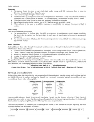
Oxidation of elements could occur either through the slag phase or by direct contact of oxygen with the elements in
steel. The latter method is more efficient; however, it must be promoted by proper adjustment of molten metal bath
distance from the oxygen injector and proper oxygen pressure. If these two factors are not taken into consideration,
then oxygen would be lost into the furnace’s atmosphere and into slag, leading to inefficient oxygen injection and
potential for violent chemical reactions in the furnace.
Sampling
At the beginning of the refining stage, it is of great importance to take a molten metal sample in order to check the
situation with regards to the target chemical composition. The sample should be taken when the temperature of the
bath has reached 1570-1580o
C. Sampling should be standardized with regards to when the sample is taken. This is
important especially when comparing the first sample results between different heats that are made by different shifts.
For example, the standard could state that the sample is taken after XMwh, or after Yton of DRI in the DRI continuous
feed phase. Regardless of the measure of that standard, it should guarantee uniformity between the different working
shifts.
The sample could also be a good indication of the final steel composition and whether there would be any additional
requirements for decarburization, desulphurization, dephosphorization, or the oxidation of any other elements that
could be present in the steel bath.
In the following section, the notations in […] indicate that the element is dissolved in molten steel, the elements in
{…} indicate that the elements are free in the atmosphere, and the elements in (…) indicate that they are dissolved in
slag
Dephosphorization
Phosphorous is required as it increases the strength of low carbon steels and increases the machinability of free-
cutting steels; however, phosphorous decreases impact resistance and ductility of steels.
The following are the chemical reactions that occur during phosphorous removal:
[Fe2P] + {O2} ↔ [Fe] + (P2O5) + heat
[Fe2P] + (FeO) ↔ [Fe] + (P2O5) – heat
(P2O5) + x(CaO) → (P2O5.xCaO) … where x=1~4 depending on the amount of lime
The following are the conditions that favor dephosphorization:
1) Temperature: 1540-1580o
C
Phosphorous oxidation with free oxygen is an exothermic reaction, and thus is best occurs at low
temperatures; higher temperatures promote phosphorous reversion
2) Oxidizing atmosphere: from the above reactions, presence of
oxygen in its freeform or from iron oxide is essential for the
phosphorous removal process. Oxygen injection also promotes
dephosphorization as it helps in increasing oxygen in the
atmosphere, FeO content, and slag/steel mixing. The ideal FeO
content for dephosphorization is 10-15% as higher amounts of
FeO would lead to lower viscosity and lower yield of the metallic
charge
10% 15%
(P)
[P]
FeO%
3) Basicity: optimum iB=2.2-2.5
4) Fluid Slag: good slag fluidity is essential for proper slag/steel
mixing (P)
[P]
2.2 2.5 Basicity
5) Good Slag/Steel Contact: this is promoted by oxygen/carbon
injection into the furnace and the formation of carbon monoxide
bubbles, which allow for greater surface contact between slag
and steel
6) Deslagging: slag must be continuously removed in order to get
rid of phosphorous-rich slag, and prevent phosphorous reversion
The following factors should be considered for good dephosphorization:
1) If the metallic charge is know to have a high content of phosphoro
for dephosphorization. Limestone has a cooling effect on the furnace; this is particularly required in modern
us, then limestone would be more suited
AMIR MISHRIKY
20](https://image.slidesharecdn.com/88776543-the-melt-shop-process-211026192259/85/88776543-the-melt-shop-process-22-320.jpg)
![THE MELT SHOP PROCESS JUNE 2005
electric are furnaces that are equipped with high flow-rate oxygen injection facilities, which in turn increase
the heating rate. Moreover, limestone calcination in the EAF produces carbon dioxide gas, which helps in
stirring the molten metal bath with slag
2) If burnt lime is being used, then dephosphorization should be executed at an early stage of refining in order
to guarantee that the temperature is low enough
3) If temperature increases above 1580o
C then some scrap or DRI should be added to decrease the molten metal
bath temperature and prevent phosphorous reversion
4) Iron oxide (FeO) is a good substitute for limestone as its reaction is endothermic, and it readily provides an
oxidizing atmosphere. However, adding too much FeO and increasing the bath temperature at the same tome
would lead to phosphorous reversion and heavy reactions in the furnace with carbon (above 1600o
C)
5) Presence of elements with higher affinity towards oxygen (C, Si, Mn, and Cr) decreases dephosphorization
rate
6) Carbon injection has two opposing effects on dephosphorization rate: 1) carbon reacts with oxygen to form
carbon monoxide, which provides good bubbling and mixing of slag and steel, and 2) carbon consumes
oxygen
Silicon Removal
The following are the chemical reactions that occur during silicon removal:
[Si] + {O2} → (SiO2) + 8.5KWh/Kg Si
[Si] + [FeO] → (SiO2) + [Fe]
Silicon could be oxidized by either free oxygen from the atmosphere or the oxygen from iron ore (FexOy). The earlier
method is preferred due to the following reasons:
1) If iron ore is added to the furnace, we shall have more impurities and thus more refining time will be required
2) Iron ore will require more energy to melt
3) The reaction between silicon and oxygen is exothermic, and thus it releases energy into the furnace, which
might decrease the overall required melting time and electrical energy consumption
To determine the amount of oxygen required for silicon oxidation:
Si + O2 → SiO2
28 + 32 → 60 (equation expressed in molar weights)
1Kg Si requires 32
/28 ≅ 1.14Kg O2
32Kg O2 ≅ 22.4Nm3
O2
∴ 1.14Kg O2 ≅ 0.8Nm3
O2
∴ Ideally, 1Kg Si requires 0.8Nm3
O2 to be oxidized ≅ 0.08Nm3
O2/0.01% Si
However:
1) The reaction is only 80% efficient
2) Reaction efficiency is affected by the quality of oxygen injection (oxygen flow-rate, oxygen pressure should
be greater than 8bar, and the injection angle)
High silicon scrap may have adverse effects on phosphorous removal:
1) Reaction is exothermic, thus molten metal bath temperature will increase (low temperature is required for
phosphorous removal)
2) As SiO2 increases, slag basicity decreases (high basicity is required for phosphorous removal)
3) Silicon has higher affinity towards oxygen than phosphorous
Manganese Removal
The following are the chemical reactions that occur during manganese removal (50-70% efficient):
[Mn] + {O} → (MnO) + 2KWh/Kg Mn
The following conditions favor manganese removal:
1) Low temperature
2) Low slag basicity
3) Slag removal
Manganese recovery occurs through the following reaction:
(MnO) + [C] + heat → [Mn] + {CO}
The following conditions favor manganese recovery:
AMIR MISHRIKY
21](https://image.slidesharecdn.com/88776543-the-melt-shop-process-211026192259/85/88776543-the-melt-shop-process-23-320.jpg)
![THE MELT SHOP PROCESS JUNE 2005
1) High temperature
2) High slag basicity
3) No slag removal
Following the same basis for calculations as that shown with silicon:
Ideally, 1Kg Mn requires 0.2Nm3
O2 to be oxidized ≅ 0.02Nm3
O2/0.01% Mn
Chromium Removal
The following are the chemical reactions that occur during chromium removal:
[Cr] + {O} ↔ (Cr2O3) + heat
[Cr] + (FeO) ↔ [Fe] + (Cr2O3) – heat
The following conditions favor chromium removal:
1) Low temperature: 1570-1580o
C
2) Low slag basicity: 1.8-2.1 (Cr2O3 is acidic)
3) Slag composition should be lower in silicon and manganese as both these elements have higher affinity
towards oxygen than chromium, and thus acts as protective elements for chromium oxidation
Additional comments:
- Calcium requires 0.28Nm3
O2/Kg Calcium to be removed
- Magnesium requires 0.05Nm3
O2/0.01% Magnesium to be removed
- If C≥0.2%, 0.08Nm3
O2/[0.01%Si].t, 0.05Nm3
O2/[0.01%Mg].t, 0.1Nm3
O2/[0.01%C].t, 0.01Nm3
O2/[0.01%Mn].t, 0.9Nm3
O2/[0.001%S].t, where t: tons of liquid steel
Decarburization
This occurs by the following reactions:
C + ½O → CO + 2.75KWh/Nm3
O2
CO + ½O → CO2 + 7KWh/Nm3
O2
C + O2 → CO2 + 4.88KWh/Nm3
O2
The following are the observed effects of decarburization:
1) Decarburization consumes oxygen and thus has an adverse effect on dephosphorization
2) The formed gases from the decarburization process accelerate desulphurization and dephosphorization,
promote removal of nitrogen and hydrogen, and help homogenize the temperature and chemical
composition of the molten metal bath
Desulphurization
Sulfur is removed by lime addition:
[FeS] + (CaO) → (CaS) + (FeO) – heat
Conditions for desulphurization:
1) High temperature: >1600o
C
2) High basicity: 2-2.5
3) Reducing atmosphere: low oxygen and FeO
Since desulphurization occurs in the refining stage, therefore it is normal to have high levels of oxygen and
FeO in the furnace. In case of slightly higher levels of sulfur in the metallic charge, a normal practice is to
slightly increase the amounts of charges lime. However, in case of excessive sulfur content in the metallic
charge, the molten metal bath has to be deoxidized first by the addition of manganese, silicon, or carbon
The normal procedure for desulphurization is:
1) Deslag
2) Add 500Kg of lime
3) Inject carbon and a low amount of oxygen
Desulphurization is normally executed in the ladle furnace, and the procedure for such a process will be discussed in
the ladle furnace section of this manual.
AMIR MISHRIKY
22](https://image.slidesharecdn.com/88776543-the-melt-shop-process-211026192259/85/88776543-the-melt-shop-process-24-320.jpg)
![THE MELT SHOP PROCESS JUNE 2005
THE TAPPING PROCESS & TAPPING ADDITIONS
Tapping has to be done in a pre-heated ladle due to the following reasons:
1) Ladle refractory must be maintained at a high temperature to prevent any cracking as it comes into contact
with molten steel
2) The Ladle should be free of oxygen due to the following:
- If oxygen>50ppm, it might create effervescences that would lead to ladle overflows
- Oxygen could re-oxidize synthetic slag created in the ladle leading to inefficient desulphurization in
the ladle furnace
- Excess oxygen could lead to low alloy additions yield
- Ladle furnace process would be prolonged due to additional deoxidation
- Increased refractory consumption in ladles
- Poor final product quality
At tapping, the following occurs:
1) The furnace is deslagged
2) Tapping chemical composition depends on the required steel grade, but could be in the following range:
C% Mn% P% S% Cu% Ni% Cr% Mo% Sn% N2 [ppm] O2 [ppm] H2 [ppm]
varies 0.07 0.01 0.030-0.035 varies 0.1 0.08 0.01 0.002 50-70 varies <10
For the varying elements, the tapping analysis depends on the process variables. In case of C% and O2 ppm, it
depends on the required steel grade. With low carbon steels, tapping could occur at as low as 0.03% C, and
as high as 900ppm, whereas with medium carbon steels, tapping could occur at 0.10% C, and 400ppm O2.
Furthermore, a relation exists between O2 ppm and C% as follows:
O2 [ppm] = 27.5/[C%] + 110
Regardless of what the tapping chemical analysis will be, the most important criterion is to guarantee that all
the elements are within the desired range. In the ladle furnace, the process is not capable of removing any of
the elements except for sulfur. Moreover, some elements are liable to some pickup in the ladle furnace, such
as carbon (from the ladle furnace electrodes), nitrogen, hydrogen, and silicon (if some EAF slag has been
tapped into the ladle). For these elements, it is preferable to tap close to, or below, the minimum allowable
range
Precaution: If at the end of the heat, it is required to perform some decarburization, then the following steps should
be followed:
1) Take a steel sample
2) Ensure that the temperature is 1590-1600o
C, to prevent any vigorous reactions that could occur at higher
temperatures
3) Power-off, and lift the electrodes
4) Evacuate the platform, and inject oxygen for 2min
5) Take a sample
6) Repeat if required
Carbon/oxygen reactions at temperatures above 1600o
C are very vigorous, and could cause boiling of the molten
metal bath. The reasons for the occurrence of these reactions could either be improper coke addition in the scrap
buckets, excessive coke addition into the furnace through the materials handling system, or breakdown of any skulls
during the refining stage (highest possibility for the last reason is during deslagging and tapping, which is while the
furnace is being tilted)
3) Proper tapping temperature, which is approximately 1640o
C for most steel grades. Tapping temperature
depends on the liquidus temperature of the steel grade in production. Tapping has to occur at a temperature
above liquidus due to the heat losses caused by the following:
- Tapping additions
- Contact of steel with atmosphere
- Contact of steel with ladle refractory
- Stirring of steel during tapping
- Possible ladle deslagging
- Ladle transfer time to ladle furnace
AMIR MISHRIKY
23](https://image.slidesharecdn.com/88776543-the-melt-shop-process-211026192259/85/88776543-the-melt-shop-process-25-320.jpg)
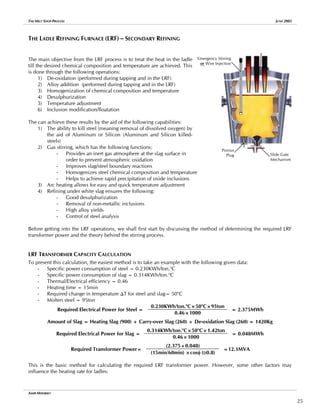
![THE MELT SHOP PROCESS JUNE 2005
1) Ladle refractory lining status; fresh refractory would require greater heating rates than older ladles, and ladles
at the end of their campaigns have greater heat losses
2) Ladle pre-heating time and temperature
3) Specific ladle surface area per ton of steel; the greater this ratio, the greater the heat losses
4) Specific electrical power input (KWh/ton.min), which is a characteristic of the transformer specifications; the
greater the input per ton of molten steel, the greater the potential heating rate
5) Mode and effectiveness of stirring in the ladle
Note: Proper LRF transformer selection should allow for 3-4o
C/min of temperature increase; this rate will guarantee
moderate heating speed that will allow for the metallurgical processes to occur at the same time
Heat losses in the LRF could be approximated as follows:
- 1o
C/100Kg of additive material
- 0.80o
C/min with strong stirring, and slightly lower with soft bubbling
- 1.80o
C/min with the fumes suction system in operation
- 0.65o
C/min with the ladle cover on
- 0.80o
C/min with power-off and roof-off
- 10o
C during calcium treatment
LRF electrical power consumption could be summarized by the following:
- 54% total losses, of which 42% are heating losses to refractory, and 12% losses in resistance of electrical
cables
- 46% efficient heating energy, of which 18% is used for metal heating, 9% for alloy melting, and 9% for
fusing the slag builder
One approximate method for this calculation is:
LRF Transformer Capacity ≅ 25% of EAF Transformer Capacity
Another approximation for determination of the required LRF transformer power is:
LRF Power per Ladle square meter of Ladle Surface ≅ 2MW/m2
If power>2MW/m2
then we could have slag over-temperature, which would lead to excessive refractory wear
STIRRING MECHANISMS
Why is stirring required in ladles?
- It provides uniform heat distribution throughout the ladle
- Prevents overheating of slag, which could cause excessive wear in the ladle slag line
- Guarantees uniform chemical composition of molten metal
- The LRF metallurgical processes such as de-oxidation, slag formation, alloying, desulphurization, temperature
adjustment, and inclusion floatation require good stirring
Gas Stirring
- Inert gases are injected at the ladle bottoms to obtain the stirring effect ; the two
most commonly used gases are Argon and Nitrogen; the latter can only be used in
steel grades where the nitrogen ppm is not of great importance
- Gas stirring theory states that small gas bubbles are injected at the bottom of the
ladle; as these bubble rise in the molten steel, they increase in size by the effect of
temperature and drop in pressure
- Design of the stirring system, including gas pressure and flow-rate, and the size of
the pores in the porous plug is a factor of the following:
a] Gas bubbles should be as small as possible such that they can attain the temperature of the molten
steel in minimum time possible; for that reason, the pores in the porous plug need to be very fine
b] Gas pressure should be at least equal to the molten steel pressure at the bottom of the ladle in
order to have enough force to enter
Porous Plug
- Positioning of the porous plugs follows a few criteria:
AMIR MISHRIKY
26](https://image.slidesharecdn.com/88776543-the-melt-shop-process-211026192259/85/88776543-the-melt-shop-process-28-320.jpg)
![THE MELT SHOP PROCESS JUNE 2005
a] Placed at a distance close to the midpoint of the ladle
radius, or slightly closer to the ladle walls
b] Positioned between two electrodes (positioning the porous
plug closer to one electrode than the other could cause
excessive wear in the phase right above the electrode)
c] It is preferable to have the additive hopper positioned right
above the porous plug to have the best mixing effect
- Visual inspection is of great importance for gas stirring:
a] During sulfur removal, strong bubbling (high flow)
b] During alloy addition, medium bubbling (moderate flow)
c] During inclusion floatation, soft bubbling (low flow ~10-
15Nm3
/hr)
Porous Plug Assembly
- Stirring could have an effect on oxygen ppm measurements. During strong stirring, the steel/slag mixing
could lead to some oxygen pickup; this could lead to distortion of the oxygen ppm measurements. Therefore,
a general rule should be that oxygen ppm measurements should be taken without any stirring activity
- The causes of bad stirring could be as follows:
a] Gas leakage from the argon/nitrogen line
b] Tapping from the EAF at a temperature less than Tliquidus+50o
C, which would lead to solidification
of molten steel on the porous plug
Inductive Stirring
An electromagnetic coil is fixed on the ladle outside shell and it forms a magnetic field which creates stirring forces in
molten steel inside the ladle. Inductive stirring requires a greater initial cost and lower running cost; also, some
studies have shown that the overall long-run cost for inductive stirring is lower than gas stirring. However, only one
out of four ladles would have inductive stirring
Gas Stirring Inductive Stirring
Mixing pattern Irregular Regular/controlled
Inclusions floatation Mediocre Good
Mixing speed Low High
Energy distribution More at surface Even distribution
Slag/steel contact Very good Good
Exposure of steel to atmosphere Risk exists Risk is minimal
Carbon pickup Risk exists Risk is minimal
TAPPING FROM EAF
Factors affecting tapping temperature:
1) Steel melting temperature is inversely proportional to the carbon content of the heat
2) The type of alloying elements and their melting temperatures; if the alloying elements have a high melting
temperature, then a high tapping temperature would be required
3) Expected temperature drop till arrival for treatment at LRF; if the ladle is expected to remain in the parking
position for a long time, then a higher tapping temperature is advisable
4) Ladle life (as previously mentioned)
Important: Molten steel tapped from the EAF must be free from oxygen and phosphorous-rich slag in order to obtain
the highest yield possible from the alloying elements, to prevent phosphorous reversion, and enable proper
desulphurization
Tapping Additions
Three types of tapping additions are available and they should be added in the following order:
1) De-oxidants are first added to remove dissolved oxygen from the molten steel and to ensure best yield from
ferroalloys
2) Ferroalloys
3) Slag formers
De-oxidants
De-oxidation is essential due to the following reasons:
AMIR MISHRIKY
27](https://image.slidesharecdn.com/88776543-the-melt-shop-process-211026192259/85/88776543-the-melt-shop-process-29-320.jpg)
![THE MELT SHOP PROCESS JUNE 2005
1) To ensure that there would be good yield from the alloying elements. If alloying elements are added while
there is high content of dissolved oxygen, then these elements will react with oxygen and form oxides.
Moreover, if carbon is one of these alloying elements, then a heavy reaction could occur, especially at high
levels of dissolved oxygen
2) One of the conditions for desulphurization is to have a reducing atmosphere; thus de-oxidation is essential
for effective desulphurization to occur
During tapping from the EAF oxygen ppm has a direction relation with steel temperature and an inverse relation with
carbon content of tapped steel:
Oxygen ppm = Function [steel temperature, C%]
At 1550o
C [C%].[O%] = 0.0025
At 1600o
C [C%].[O%] = 0.0026
At 1650o
C [C%].[O%] = 0.0027
At 1700o
C [C%].[O%] = 0.0028
De-oxidation can be done by vacuum-degassing, which requires special equipment, or by the aid of de-oxidizing
elements. The difference between both could be illustrated by the following:
Vacuum Degassing De-oxidizing Elements
Amount of
oxides in bath
Dissolved Oxygen
Total Oxygen
[O]
Time
PCO at 1atm
PCO at <1atm
[O]
[C]
1) Hydrogen, nitrogen, and oxygen d
easily in molten steel, whereas carbon
monoxide and argon do not.
issolve
ther
2) At lower vapor pressures, the amount of
allowable dissolved oxygen is less, all o
factors the same
1) De-oxidation elements are introduced in
the form of ferroalloys or pure elements
2) These elements react with oxygen to
form oxides
3) The reaction products should be
removed from steel
The best two methods for de-oxidation using de-oxidizing elements are:
1) Aluminum-killed steel
2Al + 3
/2O2 → Al2O3
2(27) + 3(16) → 102
1Kg Al + 48
/54Kg O2 → 102
/54
1Kg Aluminum will react with 0.9Kg Oxygen (≅1Kg)
Aluminum yield is 50%, ∴2Kg Aluminum are required per 1Kg O2
Required Aluminum = O2[ppm] × 2 × 10⁻⁴
× Tapped Steel[ton]
- The alumina resulting from this reaction becomes part of the slag layer floating over steel
- With aluminum-killed steel, 10ppm O2 (0.001%) could be achieved in the ladle
- For low carbon steel production, a standard has been developed to use:
a] 1.60Kg/TLS of Aluminum-cones to deoxidize molten steel
b] 0.45Kg/TLS of Aluminum-flakes to deoxidize slag
2) Silicon-killed steel
Si + O2 → SiO2
28 + 2(16) → 60
1Kg Si + 32
/28 Kg O2 → 60
/28
1Kg Silicon will react with 1.14Kg Oxygen (≅1Kg)
- From the above equation and given the chemical composition and yield of ferrosilicon, the required
amount of ferrosilicon could be calculated. Ferrosilicon could contain some aluminum, which must
AMIR MISHRIKY
28](https://image.slidesharecdn.com/88776543-the-melt-shop-process-211026192259/85/88776543-the-melt-shop-process-30-320.jpg)
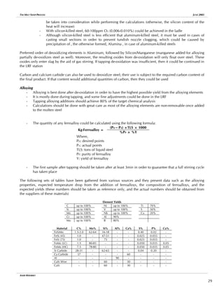
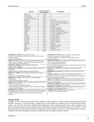
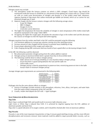
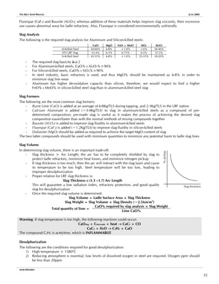
![THE MELT SHOP PROCESS JUNE 2005
3) Slag should be deoxidized and should have high sulfur capacity:
a] In case of silicon-killed steel CaO%/SiO2% ≅ 3 (this means that slag viscosity will be high, and
thus a slag fluidizer is essential)
b] In case of aluminum-killed steel, aluminum content should be 0.07% for good desulphurization
4) Good slag fluidity for slag/steel interaction (use of fluorspar, bauxite, or aluminum ashes)
5) High flow rate of gas for stirring to help achieve good slag/steel mixing, and renew the contract surface
between steel and slag
6) Suitable slag volume
7) Minimum slag passage from EAF to the ladle
WIRE FEEDING
Certain materials require special care while being fed into the ladles, and for these materials wire feeding or powder
injection could be used. The advantages of each are as follows:
Wire Feeding offers … Powder Injection offers …
More material recovery
Better composition control
Less nitrogen pickup
Effective inclusions modification
Cleaner steel
Less temperature loss
Less free-board required
Less refractory wear
Better slag/steel mixing (better desulphurization)
Shorter treatment time
Lower cost for additions
Aluminum wire is used in aluminum-killed steels for the fine tuning of aluminum content in steel and to guarantee
that the heat has been completely killed (ensure that oxygen levels are as low as possible before addition of alloying
elements). Using any method other than wire feeding or powder injection would not guarantee good yield, and might
lead to mixing of aluminum with slag rather than with steel (this is very dangerous for ladle slag line refractory)
Calcium Treatment is one of the most important steps in clean steel production. It is done to modify the shape of the
inclusions from having sharp edges (that can alter the properties of the final product) to globular inclusions (that do
not affect steel properties). The source of these inclusions is the initial presence of oxygen and sulfur in liquid steel
Schematics showing: a) Inclusions shapes (left
side), and b) Wire lancing machine
GENERAL PROCEDURE FOR LRF – ALUMINUM KILLED STEEL
1) While tapping the heat from the EAF, gas stirring
should be used to homogenize molten steel with
tapping additions; once tapping is finished, gas
stirring should be switched off
2) After addition of the final alloying element by
3min, a steel sample is taken (a good sample can only be obtained if the temperature is >1560o
C)
Summary of Types of Aluminum Used
Aluminum shots Steel de-oxidation during tapping from EAF
Aluminum powder Slag de-oxidation during tapping from EAF
Aluminum powder Ladle slag de-oxidation
Aluminum wire Ladle steel de-oxidation
3) Upon arrival of the ladle to the LRF station, the temperature of molten steel should be measured along with
oxygen ppm
AMIR MISHRIKY
33](https://image.slidesharecdn.com/88776543-the-melt-shop-process-211026192259/85/88776543-the-melt-shop-process-35-320.jpg)
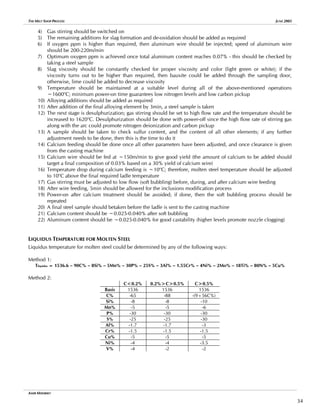
![THE MELT SHOP PROCESS JUNE 2005
Method 3:
Tliquidus=1534-A-B-C-D-E-F-G-H-I-L-M-N-O-P-Q-R-S-T
A=98.38C2
+47.73C+0.25 For C≤0.5%
B=1.25Si2
+7.95Si+0.05 For Si≤3.0%
C=5.0Mn For Mn≤2.0%
D=-0.29Ni2
+5.59Ni+0.05 For Ni≤5.0%
E=5.0Cu For Cu≤1.0%
F=8.0Sn For Sn≤8.0%
G=0.2Cr For Cr≤5.0%
H=-0.18Mo2
+5.18Mo+0.36 For Mo≤5.0%
I=3.4V-0.1 For V≤3.0%
L=0.2W For W≤5.0%
M=15Ti For Ti≤2.0%
N=0.093Al3
-0.77Al2
+5.34Al+0.13 For Al≤5.0%
O=24As For As≤1.0%
P=26P For P≤0.5%
Q=78S For S≤0.5%
R=54N For N≤1.0%
S=47O For O≤1.0%
T=750H For H≤1.0%
The final heating temperature from the LRF should be based on the following:
TLRF Final = TLiquidus + (20÷30) + estimated heat loss during ladle transport + 10o
C (in case of Ca-treatment)
LRF TROUBLESHOOTING
The following are some troubleshooting tips that would be suitable for the LRF:
- In case of excess slag carryover from the EAF, add aluminum and burnt lime
- If slag color is dark, add aluminum and burnt lime
- In case of too much slag carryover that cannot be deoxidized by the addition of aluminum and burnt lime,
the ladle should be deslagged
- During tapping from the EAF, if the tapping additions are incomplete, the first step is to check oxygen ppm,
and then proceed with the rest of the slag builders and alloying elements
- If, for some reason, there is no gas flow from the porous plug, then the emergency stirring lance should be
used; during heating and desulphurization, the lance should be positioned at the lowest position possible,
whereas during calcium-treatment, it should be used at a low flow
- If desulphurization rate is low, the following should be checked:
a] Stirring should be vigorous
b] Use both porous plug and lance if required
c] Steel temperature should be >1580o
C
d] Aluminum content should be within the allowable range
e] Slag color should be light green or white
- If the ladle is left for some time in the LRF station, a thick layer of slag and steel have formed on top, and
there is risk of electrode breakage if the arc is struck, then the following should be done:
a] A small amount of coke and aluminum should be added on the slag surface
b] An oxygen lance should be used to melt the aluminum; a very strong exothermic reaction will
occur that will melt the solidified slag/steel layer at the ladle top
AMIR MISHRIKY
35](https://image.slidesharecdn.com/88776543-the-melt-shop-process-211026192259/85/88776543-the-melt-shop-process-37-320.jpg)
![THE MELT SHOP PROCESS JUNE 2005
An Example of LRF Process Flow from ANSDK
100
Only if S>0.01% 600-1000
200
150
Argon Stirring
Top [Nl/min]
Bottom [Nl/min]
10min 20min 30min 40min
Argon
stirring
visual
check
Flux
addition
Check
Temp,
Sample,
O
2
(T>1570
o
C)
Slag
Color
Check
Check
Temp
Add
Ferroalloys
&
Al-wire
Check
Sample
Final
chemical
analysis
Check
Temp
and
Adjust
Temp
before
Ca-treatment
Final
Temp+10
o
C
Ca-wire
addition
Check
Temp
&
Sample
Check
Temp
Soft-bubbling
for
at
least
5min
Power-on
Ladle
arrival
…
check
slag
thickness
0min
300
250 150
1620o
C
1610o
C
1600o
C
1590o
C
1580o
C
1570o
C
1560o
C
AMIR MISHRIKY
36](https://image.slidesharecdn.com/88776543-the-melt-shop-process-211026192259/85/88776543-the-melt-shop-process-38-320.jpg)