Download as PDF, PPTX

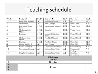
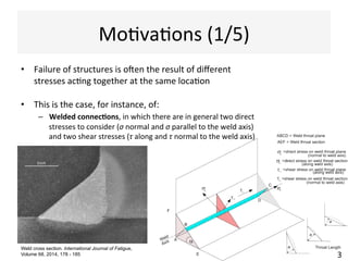
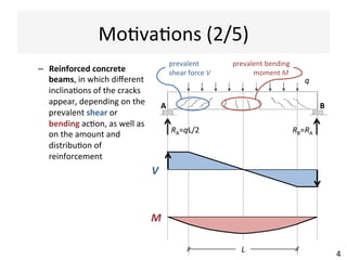
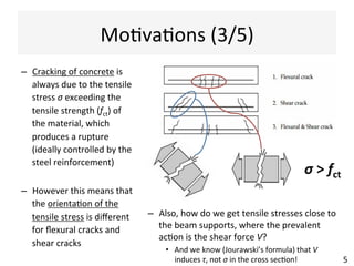
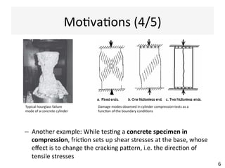
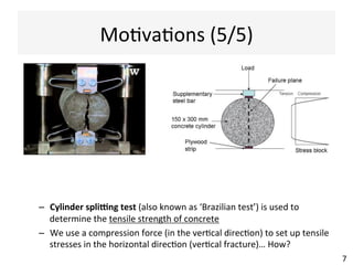

This document contains information about a teaching schedule for a course on complex stresses. It will cover topics like beam shear stresses, shear centres, virtual forces, compatibility methods, moment distribution methods, column stability, unsymmetric bending, and complex stress/strain over 11 weeks. The lectures and tutorials will be led by various staff members. The document also provides motivations for studying complex stresses, which include the fact that failure often results from different stresses acting together, and discussing examples like welded connections, reinforced concrete, and concrete cylinder tests.