The document discusses the matrix method of structural analysis. Key points include:
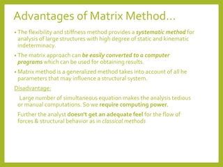
- The matrix method uses stiffness or flexibility matrices to relate forces and displacements in a structure.
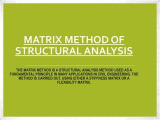
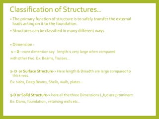
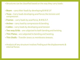
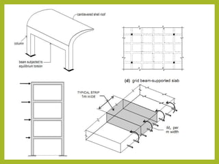
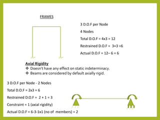
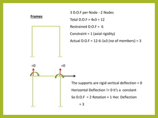
- Structures can be classified based on their dimensions and how they carry loads. Common types include beams, trusses, frames, arches, cables and plates.
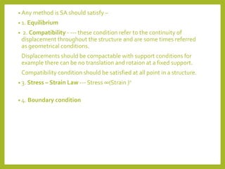
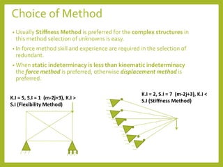
- Degree of freedom, boundary conditions, and compatibility must be considered. The stiffness method is commonly used for complex structures.
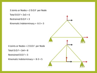
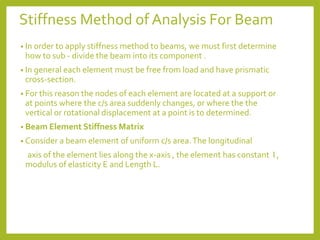
- Beam element stiffness matrices are developed relating the forces and moments to the displacements and rotations at nodes.
- Properties of stiffness matrices are discussed along with developing the load matrix and solving for displacements.


![Matrix method of SA
• In an elastic structure, there are 2 set of interrelated quantities –
forces (incl. moments, stresses, reaction etc..) & displacements
(incl. rotations, strains, twist etc..).
• The behavior of a structure can largely be defined by defining
the force – displacement relationship in the form of matrix.
Two Methods :
Flexibility Method Stiffness Method
1. Force Method Displacement Method
2. Basic Unknowns are the redundant
forces
Basic unknowns are
displacement of joints
3. [Δ] = [F][P]
[Disp Matrix] = [Flexibility Matrix] x
[Load Matrix]
[K] [Δ] = [P]
[Stiffness Matrix] x[Disp. Matrix]
= [Load Matrix]](https://image.slidesharecdn.com/advancedstructuralanalysis-230726054908-963ac143/85/Advanced-Structural-Analysis-ppt-12-320.jpg)
![M1 , Θ1
M2, Θ2
2
1
F1 , δ1
F2 , δ2
L, EI
4
2
1
3
D.O.F
[K] [Δ] = [P]
Stiffness matrix K is a 4x4 matrix with stiffness coefficients.
Stiffness coefficient Kij means the force developed at ith D.O.F due to unit
displacement at jth D.O.F such that other D.O.Fs are arrested or fixed.](https://image.slidesharecdn.com/advancedstructuralanalysis-230726054908-963ac143/85/Advanced-Structural-Analysis-ppt-16-320.jpg)
![1 2 3 4
K11 K12 K13 K14 1
K21 K22 K23 K24 2
K31 K32 K33 K34 3
K41 K42 K43 K44 4
[
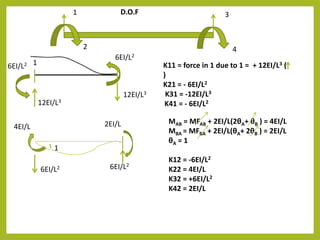
Stiffness Matrix [K]
For a simple beam
element =
F1 = K11. δ1 + K12 . Θ1 + K13. δ2 + K14. Θ2
M1 = K21. δ1 + K22 . Θ1 + K23. δ2 + K24. Θ2
F2 = K31. δ1 + K32 . Θ1 + K33. δ2 + K34. Θ2
M2 = K41. δ1 + K42 . Θ1 + K43. δ2 + K44. Θ2
F1
M1
F2 =
M2
[ K11 K12 K13 K14
K21 K22 K23 K24
K31 K32 K33 K34
K41 K42 K43 K44
[
δ1
Θ1
δ2
Θ2
[
Load Matrix
Displacement Matrix
12EI/L3 -6EI/L2 -12EI/L3 -6EI/L2
-6EI/L2 4EI/L 6EI/L2 2EI/L
-12EI/L3 6EI/L2 12EI/L3 6EI/L2
-6EI/L3 2EI/L 6EI/L2 4EI/L
[
=](https://image.slidesharecdn.com/advancedstructuralanalysis-230726054908-963ac143/85/Advanced-Structural-Analysis-ppt-19-320.jpg)
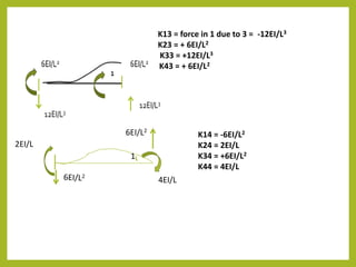
![Properties of stiffness matrix
• Symmetric Square Matrix of order n , n is number of coordinates
chosen for solution of problem
• The diagonal elements are +ve
• The element stiffness matrix is singular i.e determinant = 0 , hence
inverse cannot be obtained.
• The third row is of same magnitudes of first row but opposite in sign i.e
F1 = -F2
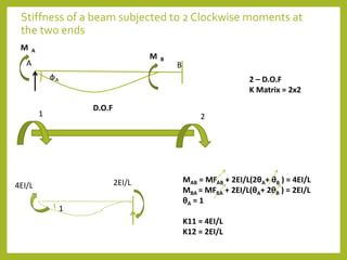
Load matrix [P]
The loads applied are transformed to equivalent joint loads [EJL] or
nodal loads.
It can be obtained = Joint load matrix – Support Reaction Matrix
[P] = [Pj] – [PL]](https://image.slidesharecdn.com/advancedstructuralanalysis-230726054908-963ac143/85/Advanced-Structural-Analysis-ppt-20-320.jpg)
![C
P P
A
B
+PL/8
MBC
MCB
PL/2
P
-PL/8 -PL/8
+ PL/8
PL/2 + PL/2
PL/2
2
3
1 5
6
0 1
0 2
[Pj] = -P 3
0 4
0 5
0 6
+PL/2
-PL/8
[PL] = PL/2 +PL/2
PL/8 + -PL/8
PL/2
+PL/8
[P] = [Pj] – [PL]
LOAD MATRIX
[ [
4](https://image.slidesharecdn.com/advancedstructuralanalysis-230726054908-963ac143/85/Advanced-Structural-Analysis-ppt-21-320.jpg)
![4EI/L
1
2EI/L K21 = 2EI/L
K22 = 4EI/L
Stiffness Matrix [K] = K11 K12 = 4EI/L 2EI/L
K21 K22 2EI/L 4EI/L
[ [
RELATION BETWEEN STIFFNESS AND FLEXIBILITY MATRIX
[Δ] = [F][P] [Disp Matrix] = [Flexibility Matrix] x [Load Matrix] ----- > 1
[K] [Δ] = [P] [Stiffness Matrix] x[Disp. Matrix] = [Load` Matrix] ---------- >2
Eq 1 x [F]
-1
[F]
-1
[Δ] = [F]
-1
[F][P]
[F]
-1
[Δ] = [P]
So , [F]
-1
= [K]](https://image.slidesharecdn.com/advancedstructuralanalysis-230726054908-963ac143/85/Advanced-Structural-Analysis-ppt-23-320.jpg)