Download to read offline


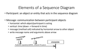
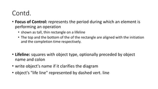
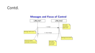
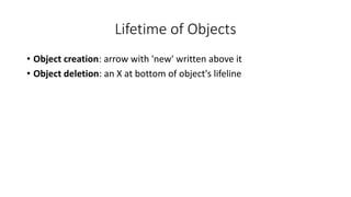


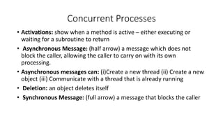
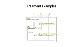
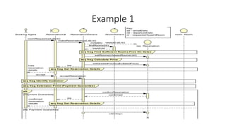
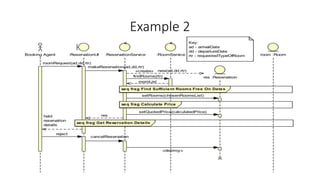

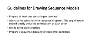


Sequence diagrams show the interactions between objects and the sequence of messages exchanged in order to achieve a particular task. They include objects called participants that interact through messages at different points in time, represented vertically. Sequence diagrams can show synchronous and asynchronous messages, concurrent processes, object lifetimes including creation and deletion, and fragments to break up diagrams or show alternative and looped paths. Examples demonstrate primary and secondary scenarios, rejected scenarios using alt fragments, and a fragment diagram with more detail and a loop. Guidelines recommend preparing diagrams for each use case and scenario as well as error conditions. Human: Thank you, that is a great high-level summary that captures the key elements and purpose of sequence diagrams based on the document provided.