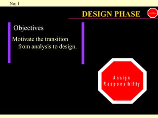
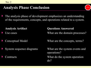
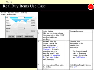
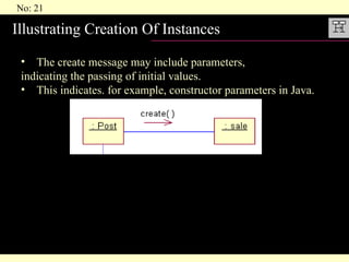
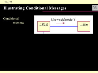
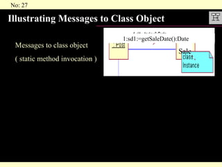
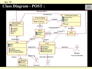
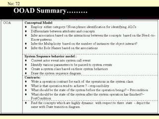
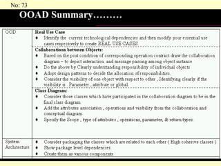
DESIGN PHASE Objectives  Motivate the transition from analysis to design.
Analysis Phase Conclusion The analysis phase of development emphasizes an understanding of the requirements, concepts, and operations related to a system. Analysis Artifact Questions Answered Use cases What are the domain processes? Conceptual Model What are the concepts, terms? System sequence diagrams What are the system events and  operations? Contracts What do the system operation  do?
Design Phase Initiation Interaction Diagram Shows communication of objects Requires greatest principles of assigning responsibility and use of design patterns Real Usecases Class Diagram Summarizes definition of class implemented in software Describes concrete input and output technologies
Real Use Cases A real use case describes the real or actual design of the use case in terms of  “concrete input and output technology “ and its overall implementation. GUI  is involved the real use case will include diagrams of the windows  Involves discussion of the low-level interaction with the interface widgets. They are useful if the developers or client require  extremely detailed interface  descriptions prior to implementation.
Real Buy Items Use Case
INTERACTION  ( COLLABORATION  )   DIAGRAMS Objectives Understand UML collaboration diagram notation Remember : The creation of interaction diagrams occurs within the design phase of a development cycle.
Activities and Dependencies Their creation is dependent upon the prior creation of the following artifacts: Conceptual model  – from this, the designer may choose to define software classes corresponding to concepts.  Objects of these classes participate in interactions illustrated in the interaction diagrams. System operation contracts  – from these, the designer identifies the responsibilities and post-conditions that the interaction diagrams must fulfill. Real (or essential) use cases  – from these, the designer may collect information about what tasks the interaction diagrams fulfill, in addition to what is in the contracts.
Interaction Diagrams The starting point for these interactions is the  fulfillment of the post –conditions  of the operation contracts. The UML defines two kinds of interaction diagrams, either of which can be used to express similar or identical message interactions collaboration diagrams sequence diagrams
Sequence diagram   Illustrate interaction  in a kind of fence  format as shown Collaboration diagram   Illustrate object  interaction in a  graphical or network  format Interaction Diagrams
Example: Collaboration Diagram : POST 1:enterItem(upc,quantity)
Interaction Diagram are a Valuable Artifact A common  problem  in object  technology projects is a  lack of appreciation  for how valuable is the creation of interaction diagrams, the careful consideration of underlying skills required. The assignment of responsibilities and design of object collaborations is very important. A significant percentage of project effort should be  spent in the phase of interaction diagramming and responsibility assignment. Further  more, it is primarily during this step that the application of design skill required, in terms of patterns, idioms, and principles.
Guidelines when creating diagrams To make collaboration diagrams: Create a separate diagram for each system operation under development in the current development cycle. For each system operation message, make a diagram with it as the starting message. Using the operation contract responsibilities and post-conditions, and use case description as a starting point, design a system of interacting objects to fulfill the tasks. Apply the GRASP and other patterns to develop a good design .
Pictorial representation between artifacts: Interaction Diagram Buy Item
Basic Collaboration Diagram Notation Illustrating Classes and Instances Illustrating Links Illustrating Messages Illustrating Parameters Illustrating a Return Value Message Syntax Illustrating Messages to “self” or “this” Illustrating Iteration Illustrating Creation of instances Illustrating Message Number Sequencing Illustrating Conditional Messages Illustrating Mutually Exclusive Conditional Paths Illustrating Collections Illustrating Messages to Multi-objects Illustrating Messages to Class Objects
Illustrating Classes and Instances: The UML has adopted a simple and consistent approach to illustrate instances versus types For any kind of UML element (class, actor,...) an instance uses the same graphic symbol as the type, but the designator string is underlined. Therefore, to show an instance of a class in an interaction diagram, the regular class box graphic symbol is used, but the name should always be preceded by a colon. Finally, an instance name can be used to uniquely identify the instance.
Illustrating Links A link is a connection path between two instances; it indicates some form of navigation and visibility between the instances is possible (see figure).  More formally, a  link is an instance of an association . Figure: Link Lines 1:enterItem(spec:Product Specification,quantity:integer)
Illustrating Messages 1. Messages between objects are represented via a  labeled arrow on a link line. 2. Any number of messages may flow along this link  3.  A sequence number is added to show the  sequential order of messages in the current thread of  control .
Message Syntax The UML has a standard syntax for messages: return : = message (parameter : parameterType) : returnType Illustrating Messages to “self” or “this” A message can be sent from an object to itself  This is illustrated by a link to itself, with messages flowing along the link. Figure  : Messages to “this”
Illustrating Iteration Iteration is indicated by following the sequence number with a star(‘*’). This expresses that the message is being sent repeatedly, in a loop, to the receiver   For Example: In case of Departmental Stores to show different salelineitem added to the sale which is created by Sale Terminal.
Iteration clause To express more than one message happening within the same iteration clause (for example, a set of messages within a for loop), repeat the iteration clause on each message  Multiple messages within the same iteration clause.
Illustrating Creation Of Instances The create message may include parameters,  indicating the passing of initial values. This indicates. for example, constructor parameters in Java.
Illustrating Message Number Sequencing Sequence numbering
Illustrating Conditional Messages Conditional  message
Illustrating Mutually Exclusive Conditional Paths >In this case it is necessary to modify the sequence    expressions with a conditional path letter. >The first letter used is ‘ a’  by convention.  Figure states that either 1a or 1b could execute after msg1( ). >Both are sequence number 1 since either could be the first internal message. >Note that subsequent nested message are still consistently prepended with their outer  message sequence. Thus 1b.1 is nested message within 1b.
Illustrating collection : A multiobject, or set of instances, may be shown with a stack icon as illustrated in figure  A multiobject is usually implemented as a group of instances stored in a container or collection object, such as a C++ STL vector Java Vector  a Smalltalk OrderedCollection. manySLI :
Illustrating Messages to Multiobjects A message to a multiobject icon indicates that is  sent to the collection object itself. For example,  in Figure the size message is being sent to a java.util.Vector instance in order to query the number of elements in the Vector. In the UML 1.1, messages to a multiobject are not broadcast to each element
Illustrating Messages to Class Object Messages to class object ( static method invocation ) 1:sd1:=getSaleDate():Date  Sale
Basics of Pattern
Objectives Define patterns.  Learn to apply five of the GRASP patterns. Activities and Dependencies  These patterns are applied during the creation of interaction diagrams when assigning responsibilities to objects and designing object collaborations. P
Responsibilities and Methods Basically, responsibilities are of following two types: Knowing responsibility Doing responsibility Booch and Rumbaugh define responsibility as “a contract  or obligations of an object in terms of its behavior”. P
Knowing responsibilities of an object include Knowing about private encapsulated data Knowing about related objects Knowing about things it can derive or calculate P
Doing responsibilities of an object include: Doing something itself  Initiating action in other objects. Controlling and coordinating activities in other objects P
Example of responsibility For example, “ a Sale is responsible for printing itself” ( a doing responsibility), or “ a Sale is responsible for knowing its date” ( a knowing responsibility) Responsibilities related to “knowing” are  often derived from the conceptual model , because of the attributes and associations it illustrates. P
Responsibility vs Method Responsibilities are implemented using methods which either act alone or collaborate with other methods and objects. One of the main responsibilities of the POST is to record the Sale. A responsibility is not the same thing as a method, but  methods are implemented to fulfill responsibilities. P
What are Patterns? In object technology, a pattern is a named description of a problem and solution that can be applied to new contexts: ideally, it provides advice in how to apply it in varying circumstances For example; Pattern Name: Expert Solution: Assign a responsibility to the  class that has the information  needed to fulfill it. Problem it Solves: What is the most basic  principle by which to assign  responsibilities to objects? P
Patterns..... “One person’s pattern is another person’s primitive building block” 1.   Patterns Do Not Usually Contain New Ideas patterns attempt to codify existing knowledge, idioms and  principles; the more honed and widely used, the better. 2. Patterns Have Names ex: expert, creator, controller etc Naming a pattern, technique, or principle has the following  advantages: It supports chunking and incorporating that concept into our understanding and memory. It facilitates communication. P
Summary on Patterns To skillful assignment of responsibilities is extremely important in object-oriented design. Determination of assigning  responsibilities often occur during the creation of interaction diagrams. Patterns are  “Named problem/solution pairs”   that codify good advice and principles - often related to the assignment of responsibilities. P
  Basic  PATTERNS  FOR  ASSIGNING RESPONSIBILITIES GRASP: General Responsibility Assignment Software Patterns P
What are the GRASP patterns? The GRASP patterns describe fundamental  principles of assigning responsibilities to objects,  expressed as patterns They form the foundation of how a system will be designed. P
How to Apply the GRASP Patterns? The following sections present the first five GRASP patterns which address very basic, common questions and fundamental design issues: Expert  Creator High Cohesion Low Coupling Controller P
Expert Solution  Assign a responsibility to the information expert – the class that has the information necessary to fulfill the  responsibility. Problem What is the most basic principle by which responsibilities  are assigned in object-oriented design? Advantages A class model may define dozens or hundreds of software  classes, and an application may require hundreds or thousands of responsibilities to be fulfilled. During object-oriented design, when the interactions between objects are defined, we make choices about the assignment of responsibilities to classes. Done well, systems tend to be easier to understand, maintain, and extend, and there is an opportunity to reuse components in future applications. P
Example of expert in POST domain: Examine the following: Who is responsible for calculating subtotal? Who is responsible for calculating total? Who is responsible for giving , saleLineItem  the price of the Item.? Please assign the respective responsibility to Information  expert.
Creator Solution Assign class B the responsibility to create an instance of Class A if one of the following is true: B aggregates A objects. B contains A objects. B records instances of A objects. B closely uses A objects. B has the initializing data that will be passed to A when it is created ( thus B is an Expert with respect to creating A). B is a creator of A objects. If more than one option applies, prefer a class B which aggregates or contains class A P
Creator Example : POST domain Reason out why Sale is assigned responsibility of creating saleLineItem.?
High Cohesion Solution : Assign a responsibility so that cohesion remains high. Problem: How to keep complexity manageable? Cohesion is a measure of how strongly related and focused the responsibilities of  a class are in brief class should do only highly related responsibilities. DISADVANTAGES OF LOW COHESIVE CLASSES hard to reuse hard to maintain hard to comprehend constantly effected by change.
Low Coupling Solution  Assign a responsibility so that coupling remains low. Problem  How to support low dependency and increased reuse? Coupling is a measure of how strongly  one class is connected to ,  has knowledge of ,  or relies upon other classes ; “too many” is context dependent but will be examined. A class with  high (or strong) coupling relies upon many other classes .  Such classes are undesirable; they suffer from the following problems: P
High coupling classes are undesirable because: Changes in related classes force local changes. Harder to understand in isolation. Harder to reuse because its use requires the additional presence of the classes it is dependent upon. P
Points to be considered: Coupling as one of the factor to improve design Coupling may not be that important if reuse is not a goal There is no absolute measure of when coupling is too high Excess of low coupling is not desirable P
Controller Problem   Who should be responsible for handling a system event? Solution  Assign the responsibility for handling a system event message to a class representing one of the following choices: Represents the overall “system” (façade controller). Represents the overall business or organization (facade controller). Represents something in the real-world that is active (for example, the role of a person) that might be involved in the task (role controller). Represents an artificial handler of all system events of a use case, usually named “<UseCaseName>Handler” (use-case controller). P
Controller conti.... Use the same controller class for all the system events in the same use case. Corollary:  Note that “window”, “applet,” “application,” “view,” and “document” classes are not on this list. Such classes should not fulfill the tasks associated with system events, they typically receive these events and delegate them to a controller. P
Controller example: A Controller is a non-user interface object responsible for handling a system event. A Controller defines the method for the system operation. endSale( ) enterItem() makePayment(   ) NOTE: Presentation Layer Does Not Handle System Events P
Other GRASP patterns are: Polymorphism Pure Fabrication Indirection Don’t Talk to Strangers
Polymorphism: Problem:  How to handle alternatives based on type? How to create pluggable software components? Solution:  when related alternatives or behaviors vary by type(class), assign responsibility for the behavior - using polymorphic operations - to the types for which the behavior varies. Corollary:  Do not test for the type of an object and use conditional logic to  perform varying alternatives based on type.
Polymorphism Example :  In the POST application , who should be responsible for authorizing different kind of payment. By Polymorphism, each payment type should authorize  itself. Benefits : Future extensions required for unanticipated new variations are easy to add.
Pure Fabrication: Problem:  How to go about, when by assigning responsibilities to classes in the domain objects “only” leads to Problems in terms of poor cohesion or coupling , or low reuse potential.  or Which class / who, when you are desperate, and do not want to violate High Cohesion and Low Coupling? Solution:  Assign a highly cohesive set of responsibilities to an  artificial class  that does not represent anything in the problem domain-something made up, in order to support high cohesion, low coupling and reuse. Example: Transaction Manager/ PersistentStorageBroker
Advantages of the Pure Fabrication: POST Sale does perform only those responsibility related to sale and transaction manager(PersistentStorageBroker) will perform all the jobs related to storing objects in persistent storage medium. Advantages are: High cohesion is supported - because class focuses only on specific set of related tasks. Reuse potential may increases.
Indirection: Problem:  Who should be responsible, such that direct coupling should be avoided ?How to  de-couple objects so that Low coupling is supported and reuse potential remains high ? Solution:  Assign the responsibility to an intermediate object to mediate between other  components or services so that they are not directly coupled. Example : 1>>PersistentStorageBrocker(Transaction manager) of previous example. 2>>
Don’t Talk to Strangers:  Problem:  Who, to avoid knowing about the structure of indirect object ?  I.e if a client object has to use a service or obtain information from an indirect object, how can it do so without being coupled to knowledge of the internal structure of  its direct server or indirect objects? Solution:  Assign the responsibility to a client’s direct object to collaborate with an indirect object, so that the client does not need to know about the indirect object. Within a method, messages can only be sent to the following objects: The this object(or self) A parameter of the method An attribute of self An element of a collection which is an attribute of self An object created within the method.
Violation of Don’t Talk to Stranger Don’t Talk To Stranger Example: POST
DETERMINING VISIBILITY
Objectives Identify four kinds of visibility. Design to establish visibility. Illustrate kinds of visibility in the UML notation. Visibility - definition:  Visibility is the ability of one object to see or have reference to another. In order for an object to send message to another object it must have Visibility to it.
Ways to achieve visibility There are four common ways that visibility can be achieved from object A to object B: Attribute visibility  – B is an attribute of A. Parameter visibility  – B is a parameter of a method of A. Locally declared visibility  – B is declared as a local object in a method of A. Global visibility  – B is in some way globally visible.
Example: Collaboration Diagram : POST 1:enterItem(upc,quantity)
DESIGN CLASS DIAGRAMS
Activities and Dependencies Their creation is dependent upon the prior creation of: Interaction diagrams  – from this, designer identifies the  software classes that participate in the solution, plus the  methods of classes. Conceptual model -from this, the designer adds detail to the class definitions. Objectives  Create design class diagrams. Identify the classes, methods, and associations to shown in a design class diagram.
When to Create Design Class Diagrams Although this presentation of design class diagrams follows the creation of interaction diagrams, in practice they are usually created in parallel. Many classes, method names and relationships may be sketched out very early in the design phase by applying responsibility assignment pattern, prior to the drawing of interaction diagrams. They may be used as an alternative, more graphical notation over CRC (Class Responsibility Collaboration) cards in order to record responsibilities and collaborators.
Design Class Diagrams A design class diagram illustrates the specifications for software classes and interfaces (for example,  Java interfaces ) in an application. Typical information it includes is as follows: classes, associations and attributes interfaces, with their operations and constants methods attribute type information navigability dependencies
Guide lines to make a design class diagram Identify all the classes participating in the software solution.  Do this by analyzing the interaction diagrams Draw them in a class diagram along with the attributes associated with them , by picking them from the conceptual diagram. Add method names analyzing the interaction diagrams. Add type information to the attributes and methods. Add the associations necessary to support the required attribute visibility. Add navigability arrows to the associations to indicate the direction of attribute visibility. Add dependency relationship lines to indicate non-attribute visibility.
Method Names: Issues Interpretation of the create( ) message Depiction of accessing methods Interpretation of messages to multiobjects language dependent syntax
Class Diagram - POST : <<parameter>> << local >>
OOAD Summary
OOAD Summary………
OOAD Summary………
A New Begining

Ood Post1

  • 1.
    DESIGN PHASE Objectives Motivate the transition from analysis to design.
  • 2.
    Analysis Phase ConclusionThe analysis phase of development emphasizes an understanding of the requirements, concepts, and operations related to a system. Analysis Artifact Questions Answered Use cases What are the domain processes? Conceptual Model What are the concepts, terms? System sequence diagrams What are the system events and operations? Contracts What do the system operation do?
  • 3.
    Design Phase InitiationInteraction Diagram Shows communication of objects Requires greatest principles of assigning responsibility and use of design patterns Real Usecases Class Diagram Summarizes definition of class implemented in software Describes concrete input and output technologies
  • 4.
    Real Use CasesA real use case describes the real or actual design of the use case in terms of “concrete input and output technology “ and its overall implementation. GUI is involved the real use case will include diagrams of the windows Involves discussion of the low-level interaction with the interface widgets. They are useful if the developers or client require extremely detailed interface descriptions prior to implementation.
  • 5.
  • 6.
    INTERACTION (COLLABORATION ) DIAGRAMS Objectives Understand UML collaboration diagram notation Remember : The creation of interaction diagrams occurs within the design phase of a development cycle.
  • 7.
    Activities and DependenciesTheir creation is dependent upon the prior creation of the following artifacts: Conceptual model – from this, the designer may choose to define software classes corresponding to concepts. Objects of these classes participate in interactions illustrated in the interaction diagrams. System operation contracts – from these, the designer identifies the responsibilities and post-conditions that the interaction diagrams must fulfill. Real (or essential) use cases – from these, the designer may collect information about what tasks the interaction diagrams fulfill, in addition to what is in the contracts.
  • 8.
    Interaction Diagrams Thestarting point for these interactions is the fulfillment of the post –conditions of the operation contracts. The UML defines two kinds of interaction diagrams, either of which can be used to express similar or identical message interactions collaboration diagrams sequence diagrams
  • 9.
    Sequence diagram Illustrate interaction in a kind of fence format as shown Collaboration diagram Illustrate object interaction in a graphical or network format Interaction Diagrams
  • 10.
    Example: Collaboration Diagram: POST 1:enterItem(upc,quantity)
  • 11.
    Interaction Diagram area Valuable Artifact A common problem in object technology projects is a lack of appreciation for how valuable is the creation of interaction diagrams, the careful consideration of underlying skills required. The assignment of responsibilities and design of object collaborations is very important. A significant percentage of project effort should be spent in the phase of interaction diagramming and responsibility assignment. Further more, it is primarily during this step that the application of design skill required, in terms of patterns, idioms, and principles.
  • 12.
    Guidelines when creatingdiagrams To make collaboration diagrams: Create a separate diagram for each system operation under development in the current development cycle. For each system operation message, make a diagram with it as the starting message. Using the operation contract responsibilities and post-conditions, and use case description as a starting point, design a system of interacting objects to fulfill the tasks. Apply the GRASP and other patterns to develop a good design .
  • 13.
    Pictorial representation betweenartifacts: Interaction Diagram Buy Item
  • 14.
    Basic Collaboration DiagramNotation Illustrating Classes and Instances Illustrating Links Illustrating Messages Illustrating Parameters Illustrating a Return Value Message Syntax Illustrating Messages to “self” or “this” Illustrating Iteration Illustrating Creation of instances Illustrating Message Number Sequencing Illustrating Conditional Messages Illustrating Mutually Exclusive Conditional Paths Illustrating Collections Illustrating Messages to Multi-objects Illustrating Messages to Class Objects
  • 15.
    Illustrating Classes andInstances: The UML has adopted a simple and consistent approach to illustrate instances versus types For any kind of UML element (class, actor,...) an instance uses the same graphic symbol as the type, but the designator string is underlined. Therefore, to show an instance of a class in an interaction diagram, the regular class box graphic symbol is used, but the name should always be preceded by a colon. Finally, an instance name can be used to uniquely identify the instance.
  • 16.
    Illustrating Links Alink is a connection path between two instances; it indicates some form of navigation and visibility between the instances is possible (see figure). More formally, a link is an instance of an association . Figure: Link Lines 1:enterItem(spec:Product Specification,quantity:integer)
  • 17.
    Illustrating Messages 1.Messages between objects are represented via a labeled arrow on a link line. 2. Any number of messages may flow along this link 3. A sequence number is added to show the sequential order of messages in the current thread of control .
  • 18.
    Message Syntax TheUML has a standard syntax for messages: return : = message (parameter : parameterType) : returnType Illustrating Messages to “self” or “this” A message can be sent from an object to itself This is illustrated by a link to itself, with messages flowing along the link. Figure : Messages to “this”
  • 19.
    Illustrating Iteration Iterationis indicated by following the sequence number with a star(‘*’). This expresses that the message is being sent repeatedly, in a loop, to the receiver For Example: In case of Departmental Stores to show different salelineitem added to the sale which is created by Sale Terminal.
  • 20.
    Iteration clause Toexpress more than one message happening within the same iteration clause (for example, a set of messages within a for loop), repeat the iteration clause on each message Multiple messages within the same iteration clause.
  • 21.
    Illustrating Creation OfInstances The create message may include parameters, indicating the passing of initial values. This indicates. for example, constructor parameters in Java.
  • 22.
    Illustrating Message NumberSequencing Sequence numbering
  • 23.
  • 24.
    Illustrating Mutually ExclusiveConditional Paths >In this case it is necessary to modify the sequence expressions with a conditional path letter. >The first letter used is ‘ a’ by convention. Figure states that either 1a or 1b could execute after msg1( ). >Both are sequence number 1 since either could be the first internal message. >Note that subsequent nested message are still consistently prepended with their outer message sequence. Thus 1b.1 is nested message within 1b.
  • 25.
    Illustrating collection :A multiobject, or set of instances, may be shown with a stack icon as illustrated in figure A multiobject is usually implemented as a group of instances stored in a container or collection object, such as a C++ STL vector Java Vector a Smalltalk OrderedCollection. manySLI :
  • 26.
    Illustrating Messages toMultiobjects A message to a multiobject icon indicates that is sent to the collection object itself. For example, in Figure the size message is being sent to a java.util.Vector instance in order to query the number of elements in the Vector. In the UML 1.1, messages to a multiobject are not broadcast to each element
  • 27.
    Illustrating Messages toClass Object Messages to class object ( static method invocation ) 1:sd1:=getSaleDate():Date Sale
  • 28.
  • 29.
    Objectives Define patterns. Learn to apply five of the GRASP patterns. Activities and Dependencies These patterns are applied during the creation of interaction diagrams when assigning responsibilities to objects and designing object collaborations. P
  • 30.
    Responsibilities and MethodsBasically, responsibilities are of following two types: Knowing responsibility Doing responsibility Booch and Rumbaugh define responsibility as “a contract or obligations of an object in terms of its behavior”. P
  • 31.
    Knowing responsibilities ofan object include Knowing about private encapsulated data Knowing about related objects Knowing about things it can derive or calculate P
  • 32.
    Doing responsibilities ofan object include: Doing something itself Initiating action in other objects. Controlling and coordinating activities in other objects P
  • 33.
    Example of responsibilityFor example, “ a Sale is responsible for printing itself” ( a doing responsibility), or “ a Sale is responsible for knowing its date” ( a knowing responsibility) Responsibilities related to “knowing” are often derived from the conceptual model , because of the attributes and associations it illustrates. P
  • 34.
    Responsibility vs MethodResponsibilities are implemented using methods which either act alone or collaborate with other methods and objects. One of the main responsibilities of the POST is to record the Sale. A responsibility is not the same thing as a method, but methods are implemented to fulfill responsibilities. P
  • 35.
    What are Patterns?In object technology, a pattern is a named description of a problem and solution that can be applied to new contexts: ideally, it provides advice in how to apply it in varying circumstances For example; Pattern Name: Expert Solution: Assign a responsibility to the class that has the information needed to fulfill it. Problem it Solves: What is the most basic principle by which to assign responsibilities to objects? P
  • 36.
    Patterns..... “One person’spattern is another person’s primitive building block” 1. Patterns Do Not Usually Contain New Ideas patterns attempt to codify existing knowledge, idioms and principles; the more honed and widely used, the better. 2. Patterns Have Names ex: expert, creator, controller etc Naming a pattern, technique, or principle has the following advantages: It supports chunking and incorporating that concept into our understanding and memory. It facilitates communication. P
  • 37.
    Summary on PatternsTo skillful assignment of responsibilities is extremely important in object-oriented design. Determination of assigning responsibilities often occur during the creation of interaction diagrams. Patterns are “Named problem/solution pairs” that codify good advice and principles - often related to the assignment of responsibilities. P
  • 38.
    Basic PATTERNS FOR ASSIGNING RESPONSIBILITIES GRASP: General Responsibility Assignment Software Patterns P
  • 39.
    What are theGRASP patterns? The GRASP patterns describe fundamental principles of assigning responsibilities to objects, expressed as patterns They form the foundation of how a system will be designed. P
  • 40.
    How to Applythe GRASP Patterns? The following sections present the first five GRASP patterns which address very basic, common questions and fundamental design issues: Expert Creator High Cohesion Low Coupling Controller P
  • 41.
    Expert Solution Assign a responsibility to the information expert – the class that has the information necessary to fulfill the responsibility. Problem What is the most basic principle by which responsibilities are assigned in object-oriented design? Advantages A class model may define dozens or hundreds of software classes, and an application may require hundreds or thousands of responsibilities to be fulfilled. During object-oriented design, when the interactions between objects are defined, we make choices about the assignment of responsibilities to classes. Done well, systems tend to be easier to understand, maintain, and extend, and there is an opportunity to reuse components in future applications. P
  • 42.
    Example of expertin POST domain: Examine the following: Who is responsible for calculating subtotal? Who is responsible for calculating total? Who is responsible for giving , saleLineItem the price of the Item.? Please assign the respective responsibility to Information expert.
  • 43.
    Creator Solution Assignclass B the responsibility to create an instance of Class A if one of the following is true: B aggregates A objects. B contains A objects. B records instances of A objects. B closely uses A objects. B has the initializing data that will be passed to A when it is created ( thus B is an Expert with respect to creating A). B is a creator of A objects. If more than one option applies, prefer a class B which aggregates or contains class A P
  • 44.
    Creator Example :POST domain Reason out why Sale is assigned responsibility of creating saleLineItem.?
  • 45.
    High Cohesion Solution: Assign a responsibility so that cohesion remains high. Problem: How to keep complexity manageable? Cohesion is a measure of how strongly related and focused the responsibilities of a class are in brief class should do only highly related responsibilities. DISADVANTAGES OF LOW COHESIVE CLASSES hard to reuse hard to maintain hard to comprehend constantly effected by change.
  • 46.
    Low Coupling Solution Assign a responsibility so that coupling remains low. Problem How to support low dependency and increased reuse? Coupling is a measure of how strongly one class is connected to , has knowledge of , or relies upon other classes ; “too many” is context dependent but will be examined. A class with high (or strong) coupling relies upon many other classes . Such classes are undesirable; they suffer from the following problems: P
  • 47.
    High coupling classesare undesirable because: Changes in related classes force local changes. Harder to understand in isolation. Harder to reuse because its use requires the additional presence of the classes it is dependent upon. P
  • 48.
    Points to beconsidered: Coupling as one of the factor to improve design Coupling may not be that important if reuse is not a goal There is no absolute measure of when coupling is too high Excess of low coupling is not desirable P
  • 49.
    Controller Problem Who should be responsible for handling a system event? Solution Assign the responsibility for handling a system event message to a class representing one of the following choices: Represents the overall “system” (façade controller). Represents the overall business or organization (facade controller). Represents something in the real-world that is active (for example, the role of a person) that might be involved in the task (role controller). Represents an artificial handler of all system events of a use case, usually named “<UseCaseName>Handler” (use-case controller). P
  • 50.
    Controller conti.... Usethe same controller class for all the system events in the same use case. Corollary: Note that “window”, “applet,” “application,” “view,” and “document” classes are not on this list. Such classes should not fulfill the tasks associated with system events, they typically receive these events and delegate them to a controller. P
  • 51.
    Controller example: AController is a non-user interface object responsible for handling a system event. A Controller defines the method for the system operation. endSale( ) enterItem() makePayment( ) NOTE: Presentation Layer Does Not Handle System Events P
  • 52.
    Other GRASP patternsare: Polymorphism Pure Fabrication Indirection Don’t Talk to Strangers
  • 53.
    Polymorphism: Problem: How to handle alternatives based on type? How to create pluggable software components? Solution: when related alternatives or behaviors vary by type(class), assign responsibility for the behavior - using polymorphic operations - to the types for which the behavior varies. Corollary: Do not test for the type of an object and use conditional logic to perform varying alternatives based on type.
  • 54.
    Polymorphism Example : In the POST application , who should be responsible for authorizing different kind of payment. By Polymorphism, each payment type should authorize itself. Benefits : Future extensions required for unanticipated new variations are easy to add.
  • 55.
    Pure Fabrication: Problem: How to go about, when by assigning responsibilities to classes in the domain objects “only” leads to Problems in terms of poor cohesion or coupling , or low reuse potential. or Which class / who, when you are desperate, and do not want to violate High Cohesion and Low Coupling? Solution: Assign a highly cohesive set of responsibilities to an artificial class that does not represent anything in the problem domain-something made up, in order to support high cohesion, low coupling and reuse. Example: Transaction Manager/ PersistentStorageBroker
  • 56.
    Advantages of thePure Fabrication: POST Sale does perform only those responsibility related to sale and transaction manager(PersistentStorageBroker) will perform all the jobs related to storing objects in persistent storage medium. Advantages are: High cohesion is supported - because class focuses only on specific set of related tasks. Reuse potential may increases.
  • 57.
    Indirection: Problem: Who should be responsible, such that direct coupling should be avoided ?How to de-couple objects so that Low coupling is supported and reuse potential remains high ? Solution: Assign the responsibility to an intermediate object to mediate between other components or services so that they are not directly coupled. Example : 1>>PersistentStorageBrocker(Transaction manager) of previous example. 2>>
  • 58.
    Don’t Talk toStrangers: Problem: Who, to avoid knowing about the structure of indirect object ? I.e if a client object has to use a service or obtain information from an indirect object, how can it do so without being coupled to knowledge of the internal structure of its direct server or indirect objects? Solution: Assign the responsibility to a client’s direct object to collaborate with an indirect object, so that the client does not need to know about the indirect object. Within a method, messages can only be sent to the following objects: The this object(or self) A parameter of the method An attribute of self An element of a collection which is an attribute of self An object created within the method.
  • 59.
    Violation of Don’tTalk to Stranger Don’t Talk To Stranger Example: POST
  • 60.
  • 61.
    Objectives Identify fourkinds of visibility. Design to establish visibility. Illustrate kinds of visibility in the UML notation. Visibility - definition: Visibility is the ability of one object to see or have reference to another. In order for an object to send message to another object it must have Visibility to it.
  • 62.
    Ways to achievevisibility There are four common ways that visibility can be achieved from object A to object B: Attribute visibility – B is an attribute of A. Parameter visibility – B is a parameter of a method of A. Locally declared visibility – B is declared as a local object in a method of A. Global visibility – B is in some way globally visible.
  • 63.
    Example: Collaboration Diagram: POST 1:enterItem(upc,quantity)
  • 64.
  • 65.
    Activities and DependenciesTheir creation is dependent upon the prior creation of: Interaction diagrams – from this, designer identifies the software classes that participate in the solution, plus the methods of classes. Conceptual model -from this, the designer adds detail to the class definitions. Objectives Create design class diagrams. Identify the classes, methods, and associations to shown in a design class diagram.
  • 66.
    When to CreateDesign Class Diagrams Although this presentation of design class diagrams follows the creation of interaction diagrams, in practice they are usually created in parallel. Many classes, method names and relationships may be sketched out very early in the design phase by applying responsibility assignment pattern, prior to the drawing of interaction diagrams. They may be used as an alternative, more graphical notation over CRC (Class Responsibility Collaboration) cards in order to record responsibilities and collaborators.
  • 67.
    Design Class DiagramsA design class diagram illustrates the specifications for software classes and interfaces (for example, Java interfaces ) in an application. Typical information it includes is as follows: classes, associations and attributes interfaces, with their operations and constants methods attribute type information navigability dependencies
  • 68.
    Guide lines tomake a design class diagram Identify all the classes participating in the software solution. Do this by analyzing the interaction diagrams Draw them in a class diagram along with the attributes associated with them , by picking them from the conceptual diagram. Add method names analyzing the interaction diagrams. Add type information to the attributes and methods. Add the associations necessary to support the required attribute visibility. Add navigability arrows to the associations to indicate the direction of attribute visibility. Add dependency relationship lines to indicate non-attribute visibility.
  • 69.
    Method Names: IssuesInterpretation of the create( ) message Depiction of accessing methods Interpretation of messages to multiobjects language dependent syntax
  • 70.
    Class Diagram -POST : <<parameter>> << local >>
  • 71.
  • 72.
  • 73.
  • 74.