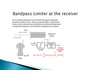
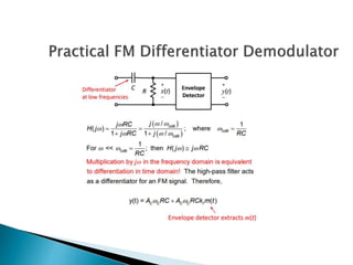
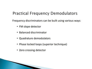
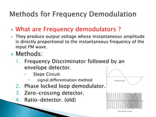
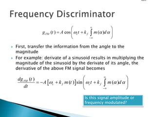
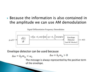
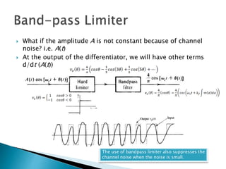
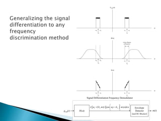
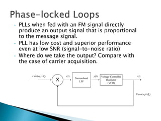
Lecture # 17
FM Demodulators
 The Objectives of Today’s Lecture is to
 Understand FM Demodulators
FM Demodulators
 What are Frequency demodulators ?
 They produce output voltage whose instantaneous amplitude
is directly proportional to the instantaneous frequency of the
input FM wave.
 Methods:
1. Frequency Discriminator followed by an
envelope detector.
 Slope Circuit
 signal differentiation method
2. Phase locked loop demodulator.
3. Zero-crossing detector.
4. Ratio-detector. (old)
 First, transfer the information from the angle to the
magnitude
 For example: derivate of a sinusoid results in multiplying the
magnitude of the sinusoid by the derivate of its angle, the
derivative of the above FM signal becomes
form
( ) cos ( )
FM c f
g t A t k m d
  


 
 
 
 

 
( )
( ) sin ( )
FM
c f c f
dg t
A k m t t k m d
dt
   


 
   
 
 

Is this signal amplitude or
frequency modulated?
 Because the information is also contained in
the amplitude we can use AM demodulation
Envelope
Detector
(and DC Blocker)
m(t)
( )
d
dt

Signal Differentiation Frequency Demodulator
gFM(t)
 
( ) sin ( )
c f c f
A k m t t k m d
   


 
  
 
 

Envelope detector can be used because
The message is always represented by the positive term
of the envelope.
 
( ) cos ( )
PM c p
g t A t k m t

 
 
( ) ( )
sin ( )
PM
c p c p
dg t dm t
A k t k m t
dt dt
 
 
   
 
 
The same idea can be used for PM demodulation. A PM signal has the form
If this signal is passed through an envelope detector, the output will be proportional to
the derivative of the message signal. An integrator will solve the problem
Envelope
Detector
(and DC Blocker)
m(t)
( )
d
d t

Signal Differentiation PM Demodulator
gPM(t)
 
( )
sin ( )
c p c p
d m t
A k t k m t
d t
 
 
  
 
 
( )
t
d 
 


( )
d m t
d t
 What if the amplitude A is not constant because of channel
noise? i.e. A(t)
 At the output of the differentiator, we will have other terms
d/dt (A(t))
The use of bandpass limiter also suppresses the
channel noise when the noise is small.
Linear Region
of Response


 
c

GFM
 
c
 
c
 
c

S
 
c
 
c
H()
Envelope
Detector
(and DC Blocker)
m(t)
Signal Differentiation Frequency Demodulator
gFM(t)
 
( ) cos ( )
c f c f
A Ck m t t k m d
   


 
 
 
 

Narrowband
LPF
X
Voltage Controlled
Oscillator
(VCO)
A sin(ct+i)
B cos(ct+o)
x(t) y(t) z(t)
• PLLs when fed with an FM signal directly
produce an output signal that is proportional
to the message signal.
• PLL has low cost and superior performance
even at low SNR (signal-to-noise ratio)
• Where do we take the output? Compare with
the case of carrier acquisition.

FM Demodulation.ppt

  • 2.
    Lecture # 17 FMDemodulators
  • 3.
     The Objectivesof Today’s Lecture is to  Understand FM Demodulators
  • 4.
  • 9.
     What areFrequency demodulators ?  They produce output voltage whose instantaneous amplitude is directly proportional to the instantaneous frequency of the input FM wave.  Methods: 1. Frequency Discriminator followed by an envelope detector.  Slope Circuit  signal differentiation method 2. Phase locked loop demodulator. 3. Zero-crossing detector. 4. Ratio-detector. (old)
  • 10.
     First, transferthe information from the angle to the magnitude  For example: derivate of a sinusoid results in multiplying the magnitude of the sinusoid by the derivate of its angle, the derivative of the above FM signal becomes form ( ) cos ( ) FM c f g t A t k m d                 ( ) ( ) sin ( ) FM c f c f dg t A k m t t k m d dt                  Is this signal amplitude or frequency modulated?
  • 11.
     Because theinformation is also contained in the amplitude we can use AM demodulation Envelope Detector (and DC Blocker) m(t) ( ) d dt  Signal Differentiation Frequency Demodulator gFM(t)   ( ) sin ( ) c f c f A k m t t k m d                 Envelope detector can be used because The message is always represented by the positive term of the envelope.
  • 12.
      ( )cos ( ) PM c p g t A t k m t      ( ) ( ) sin ( ) PM c p c p dg t dm t A k t k m t dt dt             The same idea can be used for PM demodulation. A PM signal has the form If this signal is passed through an envelope detector, the output will be proportional to the derivative of the message signal. An integrator will solve the problem Envelope Detector (and DC Blocker) m(t) ( ) d d t  Signal Differentiation PM Demodulator gPM(t)   ( ) sin ( ) c p c p d m t A k t k m t d t            ( ) t d      ( ) d m t d t
  • 13.
     What ifthe amplitude A is not constant because of channel noise? i.e. A(t)  At the output of the differentiator, we will have other terms d/dt (A(t)) The use of bandpass limiter also suppresses the channel noise when the noise is small.
  • 14.
    Linear Region of Response    c  GFM   c   c   c  S   c   c H() Envelope Detector (and DC Blocker) m(t) Signal Differentiation Frequency Demodulator gFM(t)   ( ) cos ( ) c f c f A Ck m t t k m d               
  • 15.
    Narrowband LPF X Voltage Controlled Oscillator (VCO) A sin(ct+i) Bcos(ct+o) x(t) y(t) z(t) • PLLs when fed with an FM signal directly produce an output signal that is proportional to the message signal. • PLL has low cost and superior performance even at low SNR (signal-to-noise ratio) • Where do we take the output? Compare with the case of carrier acquisition.