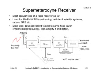
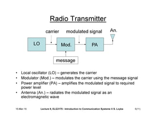
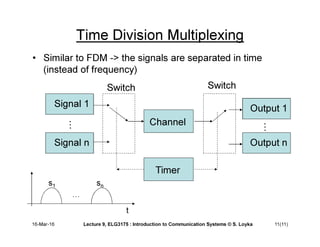
Superheterodyne Receiver
• Most popular type of a radio receiver so far.
• Used for AM/FM & TV broadcasting, cellular & satellite systems,
radars, GPS etc.
• Main idea: downconvert RF signal to some fixed lower
(intermediate) frequency, then amplify it and detect.
Antenna
Baseband
output:
voice,
video, data
AGC
AFC may be used
Incoming
EM filed
Lecture 9
c
f c
f IF
f IF
f
LO
f
16-Mar-16 Lecture 9, ELG3175 : Introduction to Communication Systems © S. Loyka 1(11)
Superheterodyne Receiver
• RF amplifier: amplifies a weak radio frequency (RF) signal coming
out of the antenna. Rejects the image frequency. Bandwidth: much
wider than the signal bandwidth.
• Mixer: together with the local oscillator downconverts the RF signal
to the intermediate frequency (IF) frequency band.
• IF amplifier: amplifies the IF signal significantly (up to 10^6) and
rejects adjacent channel signals and interference (frequency
selectivity). Its bandwidth is the same as the signal bandwidth.
• Detector (demodulator): demodulates (recovers) the message
signal.
• AGC: adjusts the IF amplifier gain according to the signal level (to
keep the average signal amplitude almost constant)
• Local oscillator: allows tuning the receiver to a desired channel
(frequency).
Lecture 9
16-Mar-16 Lecture 9, ELG3175 : Introduction to Communication Systems © S. Loyka 2(11)
Image Response
• Image response: overlaps with the desired signal &
creates interference -> must be rejected
• Image frequency : a “mirror image” of w.r.t
2
image c IF
f f f
− =
Lecture 9
16-Mar-16 Lecture 9, ELG3175 : Introduction to Communication Systems © S. Loyka 3(11)
image
f c
f LO
f
Intermediate Frequency and Image
Response
• IF must be such that the image response is rejected by
RF amplifier.
• Image frequency:
• Image rejection:
LO c IF
f f f
= + LO c IF
f f f
= −
up-side conversion down-side conversion
2
image LO IF
c IF
f f f
f f
= + =
= +
up-side conversion down-side conversion
2
image LO IF
c IF
f f f
f f
= − =
−
Lecture 9
2
RF IF
f f
∆ <
16-Mar-16 Lecture 9, ELG3175 : Introduction to Communication Systems © S. Loyka 4(11)
Example: AM Broadcast Receiver
• Incoming RF signal: IF signal:
• Up-side conversion:
• Image frequency:
850 kHz
c
f = 455 kHz
IF
f =
2 1760 kHz
image LO IF c IF
f f f f f
= + = + =
1305 kHz
LO c IF
f f f
= + =
L.W.
Couch
II,
Digital
and
Analog
Communication
Systems,
Prentice
Hall,
2001.
Note: image rejection is
due to RF amplifier only!
IF must be high enough
to reject the image
response.
On the other hand, IF
must be low enough to
provide large gain and
adjacent channel
rejection.
Lecture 9
16-Mar-16 Lecture 9, ELG3175 : Introduction to Communication Systems © S. Loyka 5(11)
Radio Transmitter
• Local oscillator (LO) – generates the carrier
• Modulator (Mod.) – modulates the carrier using the message signal
• Power amplifier (PA) – amplifies the modulated signal to required
power level
• Antenna (An.) – radiates the modulated signal as an
electromagnetic wave
LO Mod. PA
carrier modulated signal
message
An.
16-Mar-16 Lecture 9, ELG3175 : Introduction to Communication Systems © S. Loyka 6(11)
Radio Transmitter: Generalized Modulator
L.W. Couch II, Digital and Analog Communication Systems, Prentice Hall, 2001.
16-Mar-16 Lecture 9, ELG3175 : Introduction to Communication Systems © S. Loyka 7(11)
Radio Transmitter: Generalized Modulator
L.W. Couch II, Digital and Analog Communication Systems, Prentice Hall, 2001.
16-Mar-16 Lecture 9, ELG3175 : Introduction to Communication Systems © S. Loyka 8(11)
Multiplexing
• Multiplexing: combining a number of message signals
into a composite signal to transmit them simultaneously
over a wideband channel.
• Two commonly-used types: time-division multiplexing
(TDM) and frequency division multiplexing (FDM).
• TDM: transmit different message signals in different time
slots (mostly digital).
• FDM: transmit different message signals in different
frequency slots (bands) using different carrier
frequencies.
Lecture 9
16-Mar-16 Lecture 9, ELG3175 : Introduction to Communication Systems © S. Loyka 9(11)
Frequency Division Multiplexing
composite signal
spectrum
FDM system
block diagram
J.Proakis,
M.Salehi,
Communications
Systems
Engineering,
Prentice
Hall,
2002
Lecture 9
16-Mar-16 Lecture 9, ELG3175 : Introduction to Communication Systems © S. Loyka 10(11)
Time Division Multiplexing
• Similar to FDM -> the signals are separated in time
(instead of frequency)
Signal 1
Switch
Channel
Signal n
Switch
Output 1
Output n
Timer
t
s1 sn
9
16-Mar-16 Lecture 9, ELG3175 : Introduction to Communication Systems © S. Loyka 11(11)
Summary
 Superheterodyne receiver. Block diagram. Image
response.
 Multiplexing. Frequency division multiplexing. System
block diagram.
 Homework: Reading: Couch, 4.16, 4.17, 5.7, 5.8. Study
carefully all the examples and make sure you
understand them.
Lecture 9
16-Mar-16 Lecture 9, ELG3175 : Introduction to Communication Systems © S. Loyka 12(11)

Lec_9_ELG3175.pdf

  • 1.
    Superheterodyne Receiver • Mostpopular type of a radio receiver so far. • Used for AM/FM & TV broadcasting, cellular & satellite systems, radars, GPS etc. • Main idea: downconvert RF signal to some fixed lower (intermediate) frequency, then amplify it and detect. Antenna Baseband output: voice, video, data AGC AFC may be used Incoming EM filed Lecture 9 c f c f IF f IF f LO f 16-Mar-16 Lecture 9, ELG3175 : Introduction to Communication Systems © S. Loyka 1(11)
  • 2.
    Superheterodyne Receiver • RFamplifier: amplifies a weak radio frequency (RF) signal coming out of the antenna. Rejects the image frequency. Bandwidth: much wider than the signal bandwidth. • Mixer: together with the local oscillator downconverts the RF signal to the intermediate frequency (IF) frequency band. • IF amplifier: amplifies the IF signal significantly (up to 10^6) and rejects adjacent channel signals and interference (frequency selectivity). Its bandwidth is the same as the signal bandwidth. • Detector (demodulator): demodulates (recovers) the message signal. • AGC: adjusts the IF amplifier gain according to the signal level (to keep the average signal amplitude almost constant) • Local oscillator: allows tuning the receiver to a desired channel (frequency). Lecture 9 16-Mar-16 Lecture 9, ELG3175 : Introduction to Communication Systems © S. Loyka 2(11)
  • 3.
    Image Response • Imageresponse: overlaps with the desired signal & creates interference -> must be rejected • Image frequency : a “mirror image” of w.r.t 2 image c IF f f f − = Lecture 9 16-Mar-16 Lecture 9, ELG3175 : Introduction to Communication Systems © S. Loyka 3(11) image f c f LO f
  • 4.
    Intermediate Frequency andImage Response • IF must be such that the image response is rejected by RF amplifier. • Image frequency: • Image rejection: LO c IF f f f = + LO c IF f f f = − up-side conversion down-side conversion 2 image LO IF c IF f f f f f = + = = + up-side conversion down-side conversion 2 image LO IF c IF f f f f f = − = − Lecture 9 2 RF IF f f ∆ < 16-Mar-16 Lecture 9, ELG3175 : Introduction to Communication Systems © S. Loyka 4(11)
  • 5.
    Example: AM BroadcastReceiver • Incoming RF signal: IF signal: • Up-side conversion: • Image frequency: 850 kHz c f = 455 kHz IF f = 2 1760 kHz image LO IF c IF f f f f f = + = + = 1305 kHz LO c IF f f f = + = L.W. Couch II, Digital and Analog Communication Systems, Prentice Hall, 2001. Note: image rejection is due to RF amplifier only! IF must be high enough to reject the image response. On the other hand, IF must be low enough to provide large gain and adjacent channel rejection. Lecture 9 16-Mar-16 Lecture 9, ELG3175 : Introduction to Communication Systems © S. Loyka 5(11)
  • 6.
    Radio Transmitter • Localoscillator (LO) – generates the carrier • Modulator (Mod.) – modulates the carrier using the message signal • Power amplifier (PA) – amplifies the modulated signal to required power level • Antenna (An.) – radiates the modulated signal as an electromagnetic wave LO Mod. PA carrier modulated signal message An. 16-Mar-16 Lecture 9, ELG3175 : Introduction to Communication Systems © S. Loyka 6(11)
  • 7.
    Radio Transmitter: GeneralizedModulator L.W. Couch II, Digital and Analog Communication Systems, Prentice Hall, 2001. 16-Mar-16 Lecture 9, ELG3175 : Introduction to Communication Systems © S. Loyka 7(11)
  • 8.
    Radio Transmitter: GeneralizedModulator L.W. Couch II, Digital and Analog Communication Systems, Prentice Hall, 2001. 16-Mar-16 Lecture 9, ELG3175 : Introduction to Communication Systems © S. Loyka 8(11)
  • 9.
    Multiplexing • Multiplexing: combininga number of message signals into a composite signal to transmit them simultaneously over a wideband channel. • Two commonly-used types: time-division multiplexing (TDM) and frequency division multiplexing (FDM). • TDM: transmit different message signals in different time slots (mostly digital). • FDM: transmit different message signals in different frequency slots (bands) using different carrier frequencies. Lecture 9 16-Mar-16 Lecture 9, ELG3175 : Introduction to Communication Systems © S. Loyka 9(11)
  • 10.
    Frequency Division Multiplexing compositesignal spectrum FDM system block diagram J.Proakis, M.Salehi, Communications Systems Engineering, Prentice Hall, 2002 Lecture 9 16-Mar-16 Lecture 9, ELG3175 : Introduction to Communication Systems © S. Loyka 10(11)
  • 11.
    Time Division Multiplexing •Similar to FDM -> the signals are separated in time (instead of frequency) Signal 1 Switch Channel Signal n Switch Output 1 Output n Timer t s1 sn 9 16-Mar-16 Lecture 9, ELG3175 : Introduction to Communication Systems © S. Loyka 11(11)
  • 12.
    Summary Superheterodyne receiver.Block diagram. Image response. Multiplexing. Frequency division multiplexing. System block diagram. Homework: Reading: Couch, 4.16, 4.17, 5.7, 5.8. Study carefully all the examples and make sure you understand them. Lecture 9 16-Mar-16 Lecture 9, ELG3175 : Introduction to Communication Systems © S. Loyka 12(11)