Downloaded 48 times


1. The document contains 5 multi-part thermodynamics problems involving processes like compression, expansion, mixing, and throttling of steam and refrigerants. The problems require applying concepts like the first law of thermodynamics, property tables, and the principles of open and closed systems to determine properties like temperature, work, heat, and mass flow rate. 2. Problem 2 involves mixing steam at different pressures and temperatures in two tanks, then using an energy balance to find the final temperature and heat lost when equilibrium is reached. 3. Problem 3 calculates the rate of heat transfer for a steam turbine given inlet and exit conditions like pressure, temperature, velocity and power output.


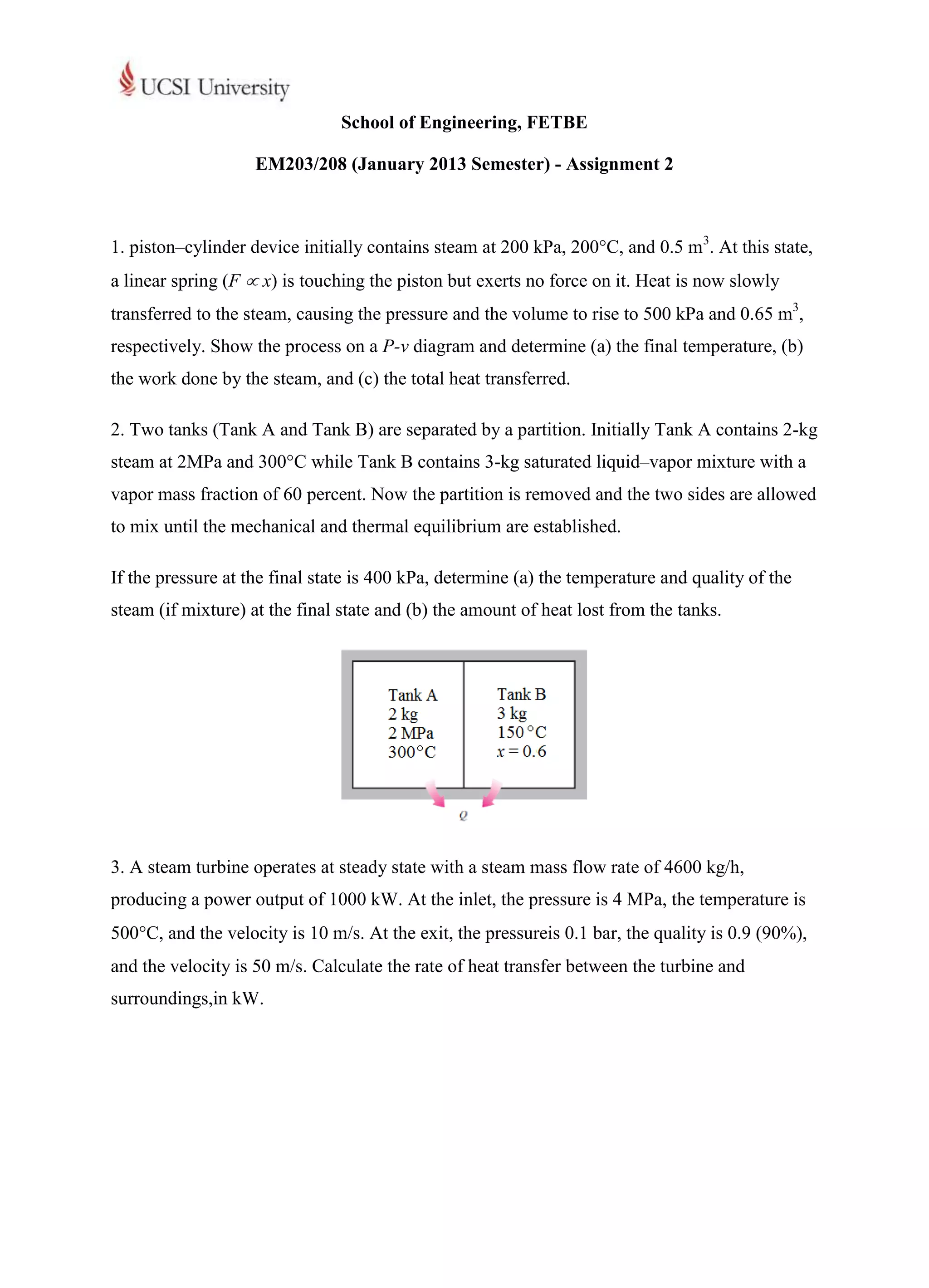
![Lecture 1a [compatibility mode]](https://cdn.slidesharecdn.com/ss_thumbnails/lecture1acompatibilitymode-130523045820-phpapp02-thumbnail.jpg?width=640&height=640&fit=bounds)


