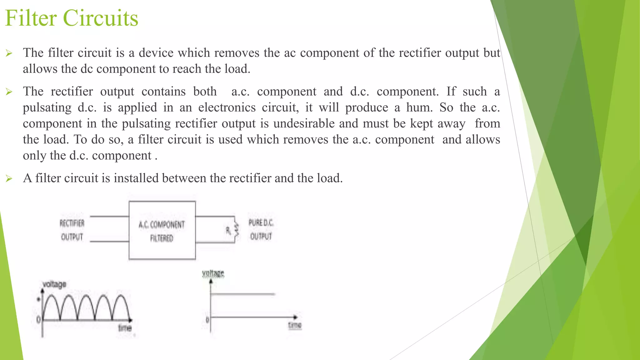
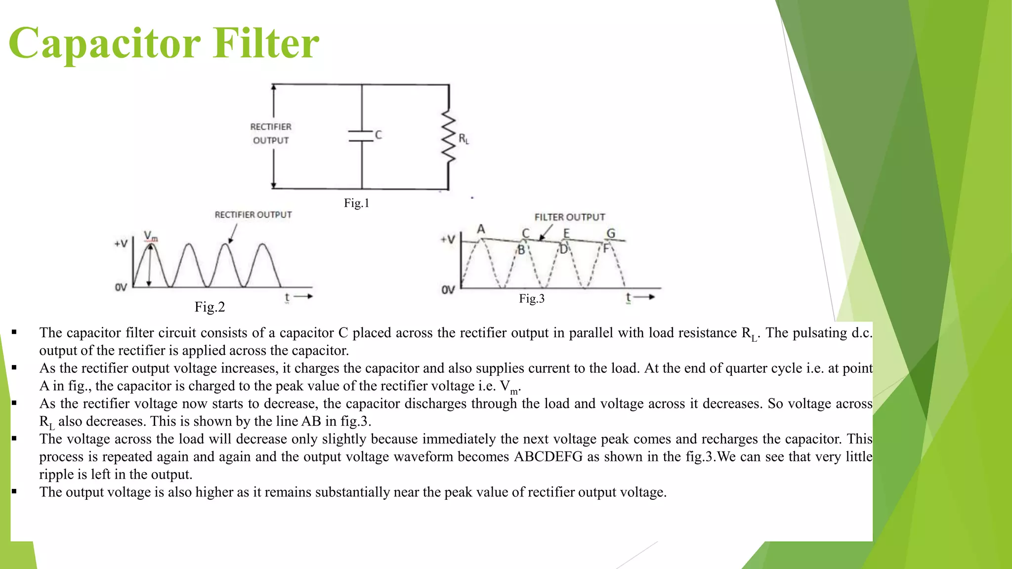
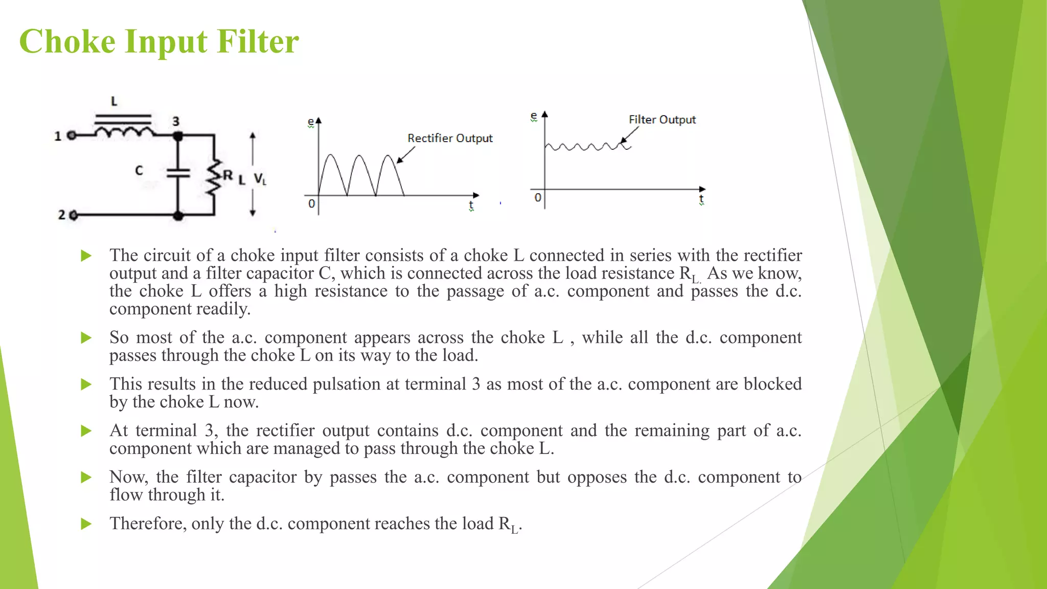
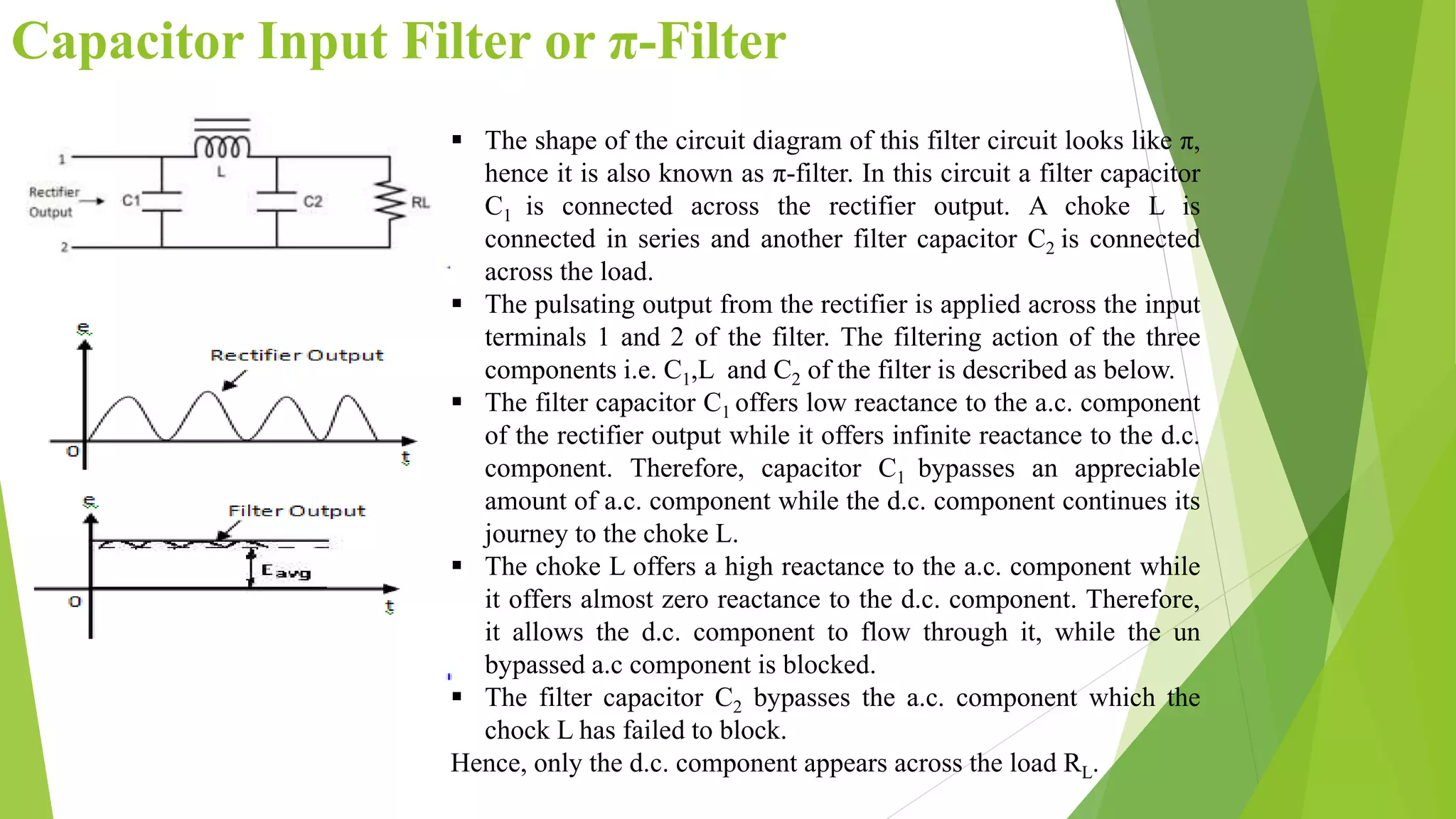
1. Filter Circuits
Syllabus based on S5 BSc physics SMITHA S
Assistant Professor
Dept. of Physics
SN College for Women
Kollam
2. Filter Circuits
The filter circuit is a device which removes the ac component of the rectifier output but
allows the dc component to reach the load.
The rectifier output contains both a.c. component and d.c. component. If such a
pulsating d.c. is applied in an electronics circuit, it will produce a hum. So the a.c.
component in the pulsating rectifier output is undesirable and must be kept away from
the load. To do so, a filter circuit is used which removes the a.c. component and allows
only the d.c. component .
A filter circuit is installed between the rectifier and the load.
3. Types of Filter Circuits
The three most commonly used filter circuits are:
Capacitor Filter
Choke input Filter
Capacitor input filter or π-Filter
4. Capacitor Filter
The capacitor filter circuit consists of a capacitor C placed across the rectifier output in parallel with load resistance RL. The pulsating d.c.
output of the rectifier is applied across the capacitor.
As the rectifier output voltage increases, it charges the capacitor and also supplies current to the load. At the end of quarter cycle i.e. at point
A in fig., the capacitor is charged to the peak value of the rectifier voltage i.e. Vm.
As the rectifier voltage now starts to decrease, the capacitor discharges through the load and voltage across it decreases. So voltage across
RL also decreases. This is shown by the line AB in fig.3.
The voltage across the load will decrease only slightly because immediately the next voltage peak comes and recharges the capacitor. This
process is repeated again and again and the output voltage waveform becomes ABCDEFG as shown in the fig.3.We can see that very little
ripple is left in the output.
The output voltage is also higher as it remains substantially near the peak value of rectifier output voltage.
Fig.1
Fig.2
Fig.3
5. Advantages of Capacitor Filter
Capacitor filter circuits are extremely popular because of its low cost.
These filters are of very small size.
It has a little weight.
It has good characteristics.
For small load currents up to 50mA this type of filter is preferred. It is commonly used in
transistor radio battery eliminators.
6. Choke Input Filter
The circuit of a choke input filter consists of a choke L connected in series with the rectifier
output and a filter capacitor C, which is connected across the load resistance RL. As we know,
the choke L offers a high resistance to the passage of a.c. component and passes the d.c.
component readily.
So most of the a.c. component appears across the choke L , while all the d.c. component
passes through the choke L on its way to the load.
This results in the reduced pulsation at terminal 3 as most of the a.c. component are blocked
by the choke L now.
At terminal 3, the rectifier output contains d.c. component and the remaining part of a.c.
component which are managed to pass through the choke L.
Now, the filter capacitor by passes the a.c. component but opposes the d.c. component to
flow through it.
Therefore, only the d.c. component reaches the load RL.
Fig.3(iii). Fig.3(ii)
7. Advantages of Choke Input Filter
The choke input filter has a high output D.C voltage.
It has no loading effect on the rectifier and power transformer.
The diode does not have to carry surge currents.
It has a very low ripple factor as compared to series inductor filter and shunt
capacitor filter.
It has very good load regulation.
It has no loading effect on the rectifier and power transformer.
It has better voltage regulation than that of π filter.
8. Capacitor Input Filter or π-Filter
The shape of the circuit diagram of this filter circuit looks like π,
hence it is also known as π-filter. In this circuit a filter capacitor
C1 is connected across the rectifier output. A choke L is
connected in series and another filter capacitor C2 is connected
across the load.
The pulsating output from the rectifier is applied across the input
terminals 1 and 2 of the filter. The filtering action of the three
components i.e. C1,L and C2 of the filter is described as below.
The filter capacitor C1 offers low reactance to the a.c. component
of the rectifier output while it offers infinite reactance to the d.c.
component. Therefore, capacitor C1 bypasses an appreciable
amount of a.c. component while the d.c. component continues its
journey to the choke L.
The choke L offers a high reactance to the a.c. component while
it offers almost zero reactance to the d.c. component. Therefore,
it allows the d.c. component to flow through it, while the un
bypassed a.c component is blocked.
The filter capacitor C2 bypasses the a.c. component which the
chock L has failed to block.
Hence, only the d.c. component appears across the load RL.
9. Advantages of Capacitor Input Filter or π-
Filter
The quality of output DC voltage is very good.
It has higher DC output voltage at heavy loads.
It is easy to design.
It has very low and smallest amount of ripple factor.
It is easy to design.
It is useful for low load current i.e. light loads.