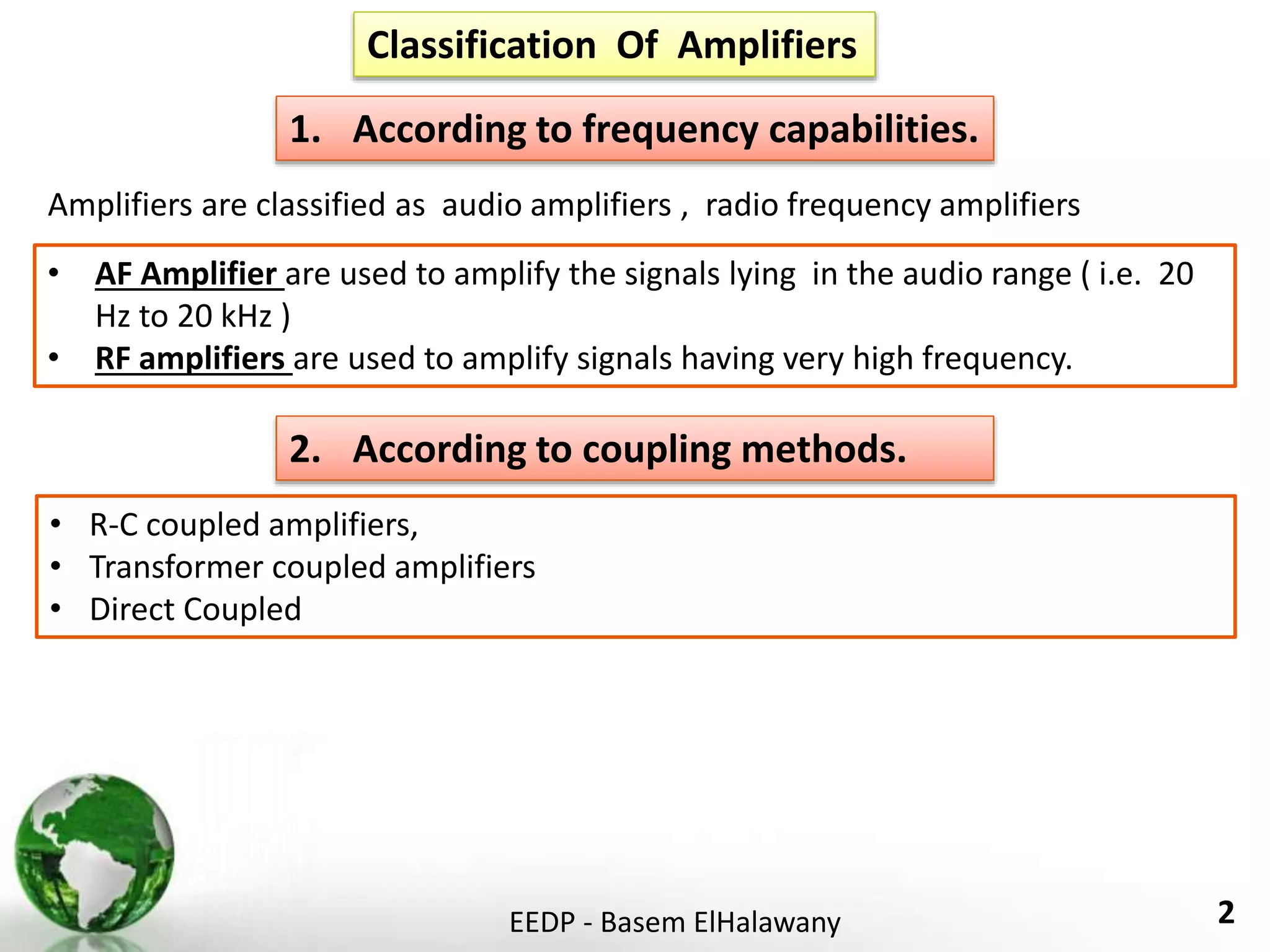
1. Amplifiers are classified according to frequency capabilities, coupling methods, and use. They can be audio frequency amplifiers, radio frequency amplifiers, voltage amplifiers, or power amplifiers.
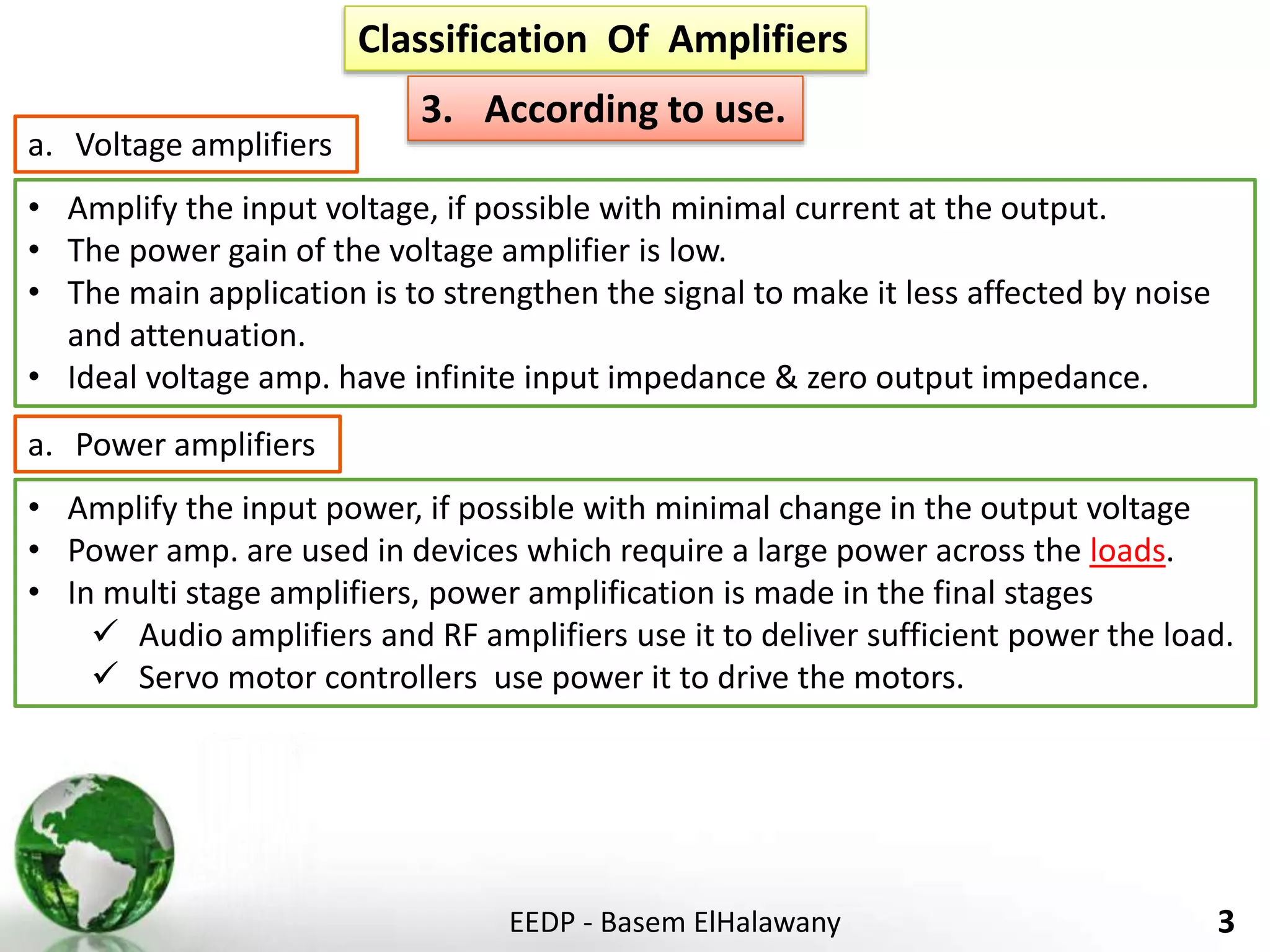
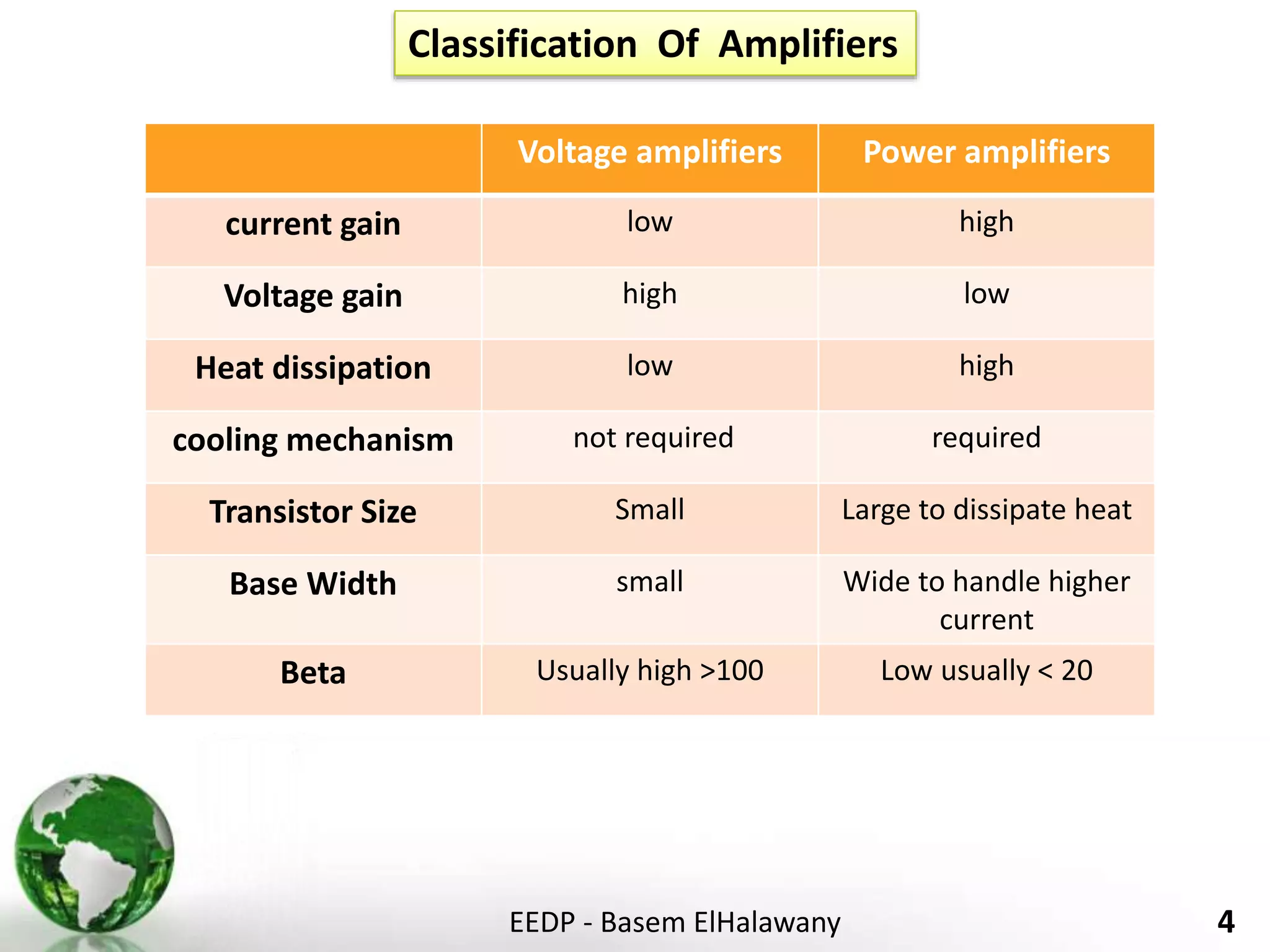
2. Voltage amplifiers aim to amplify input voltage with minimal current output, while power amplifiers amplify input power with minimal voltage change. Power amplifiers are needed for applications requiring high power loads.
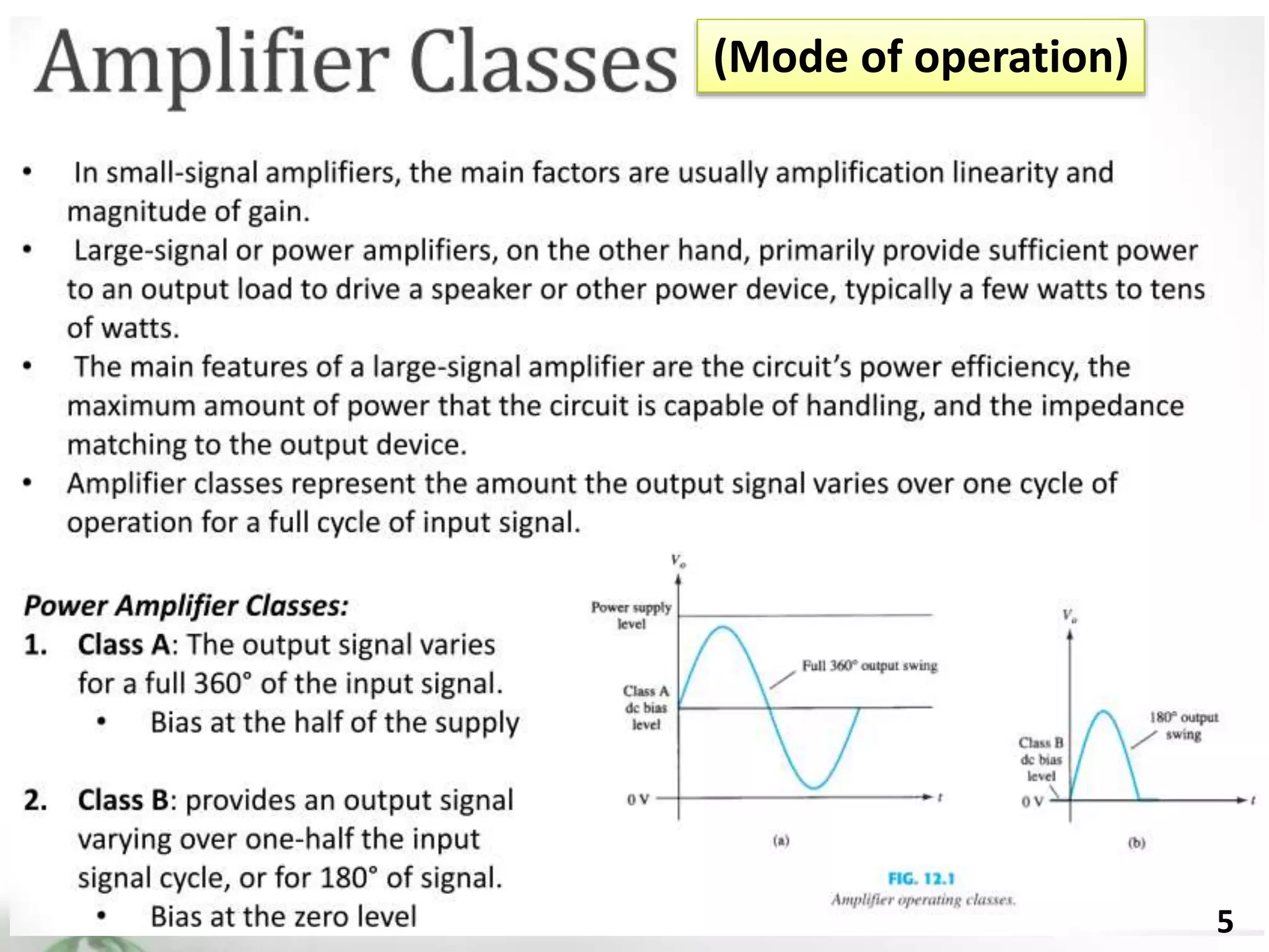
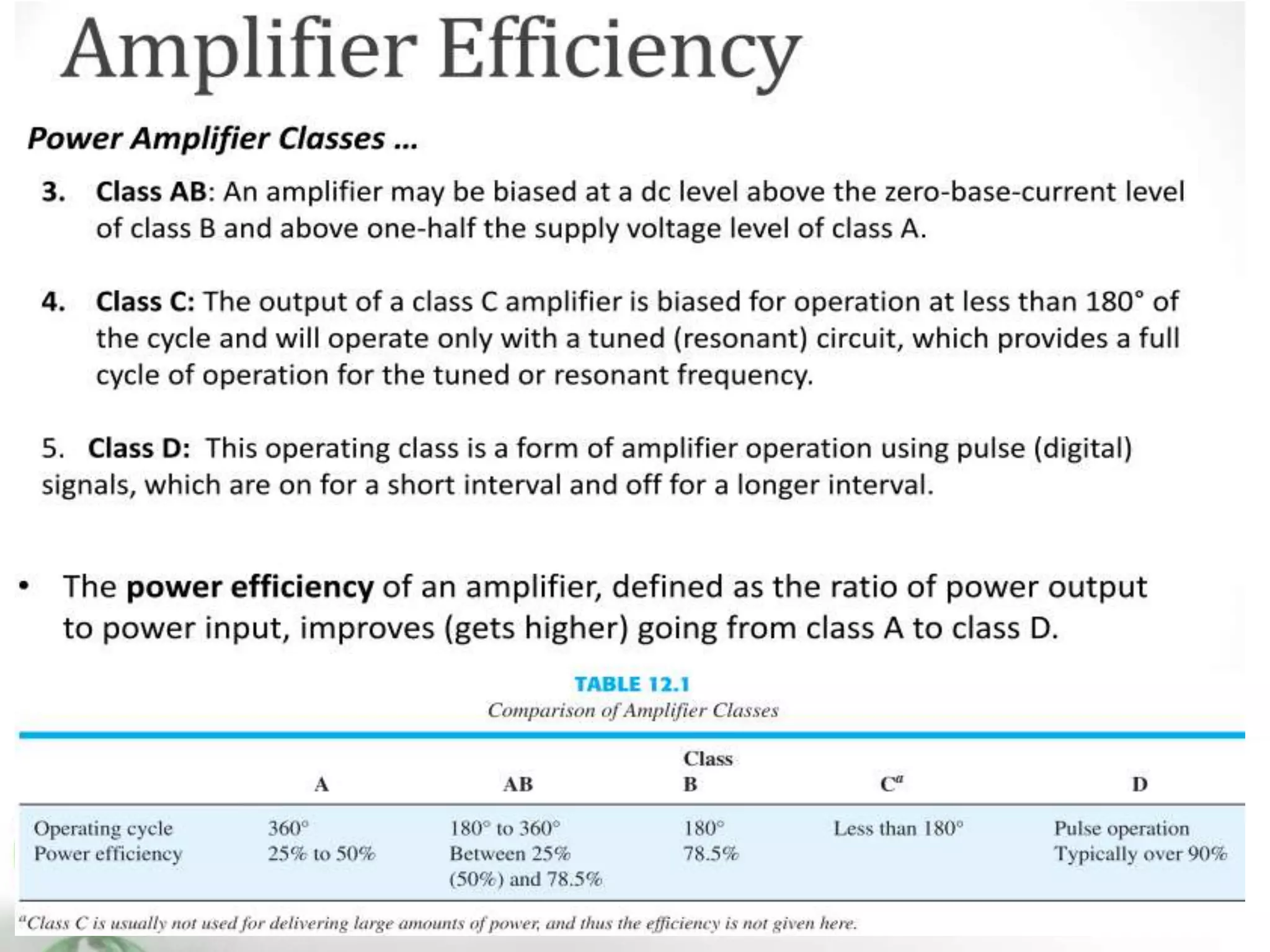
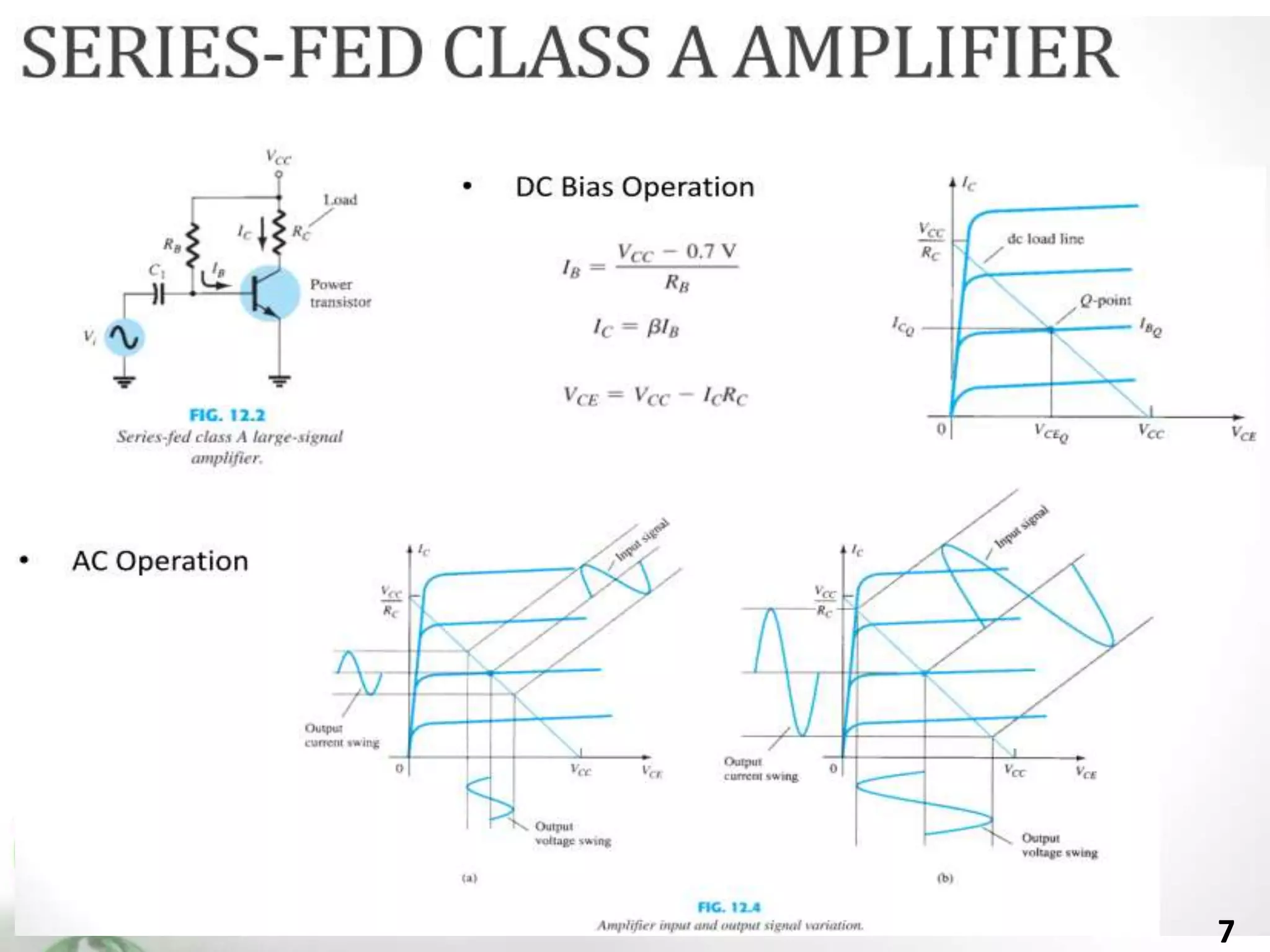
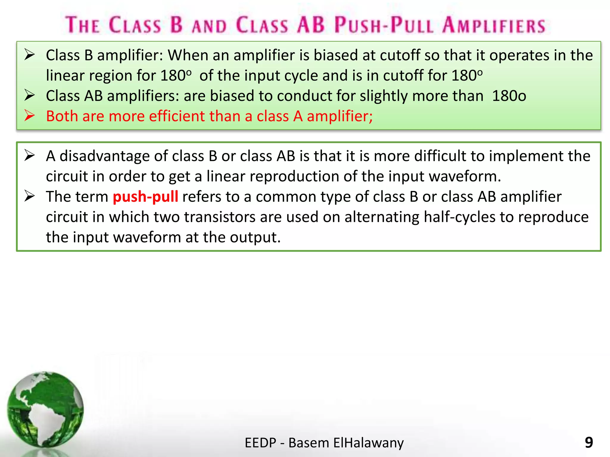
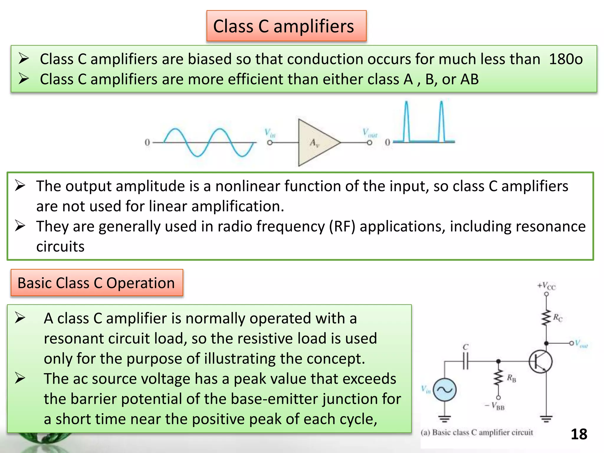
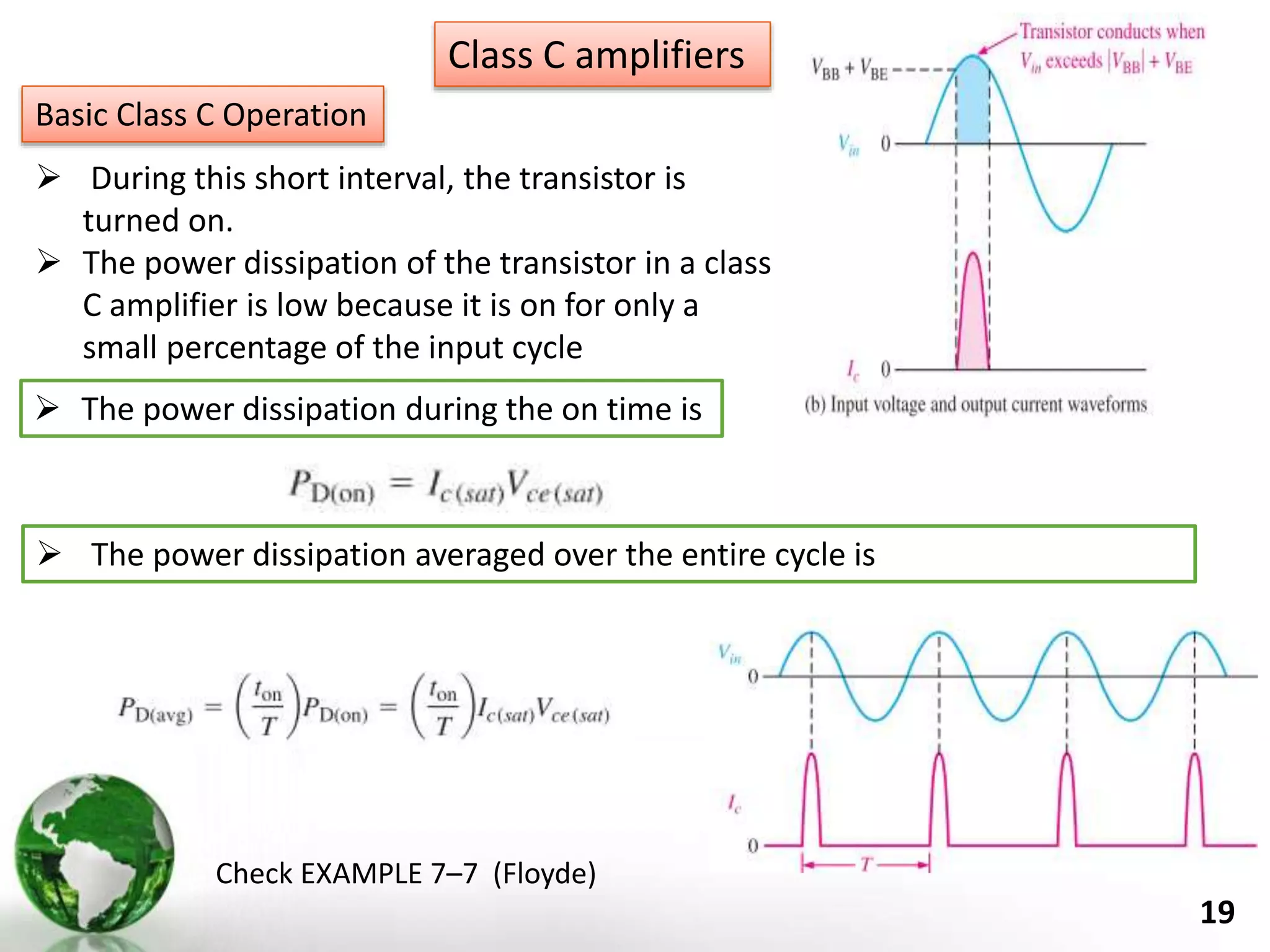
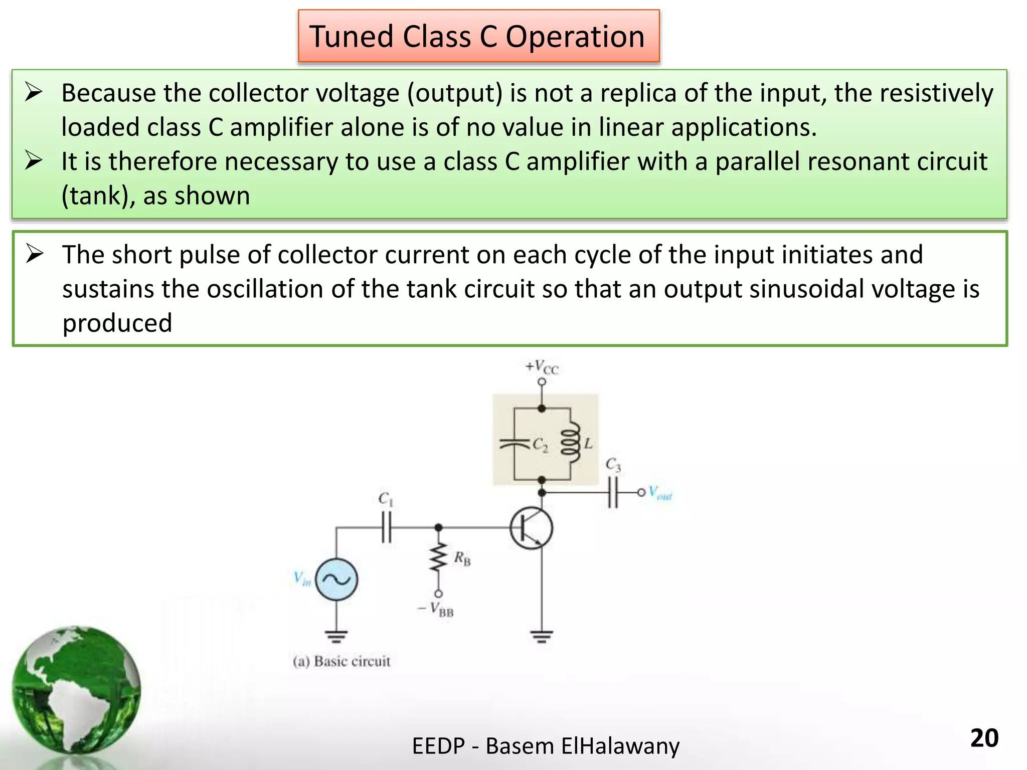
3. Amplifiers also have different classes based on their operating point, including class A operated linearly over the entire cycle, and classes B and AB operated over more than 180 degrees but with higher efficiency. Class C amplifiers are used in radio frequency applications as they operate for less than 180 degrees with even


![July07 4[1].1 power_amplifiers01](https://cdn.slidesharecdn.com/ss_thumbnails/july0741-200727121307-thumbnail.jpg?width=640&height=640&fit=bounds)


