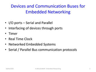
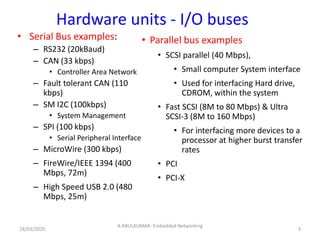
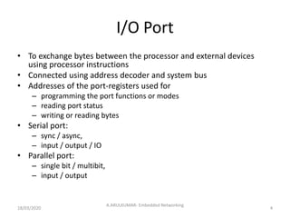
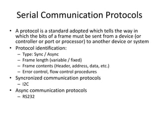
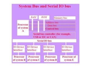
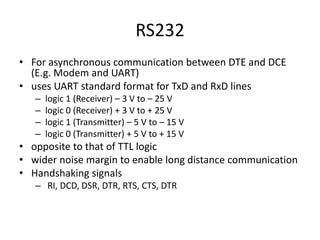
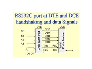
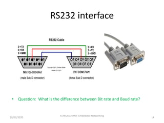
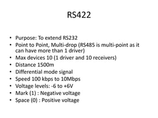
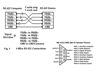
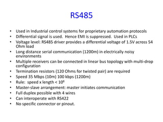
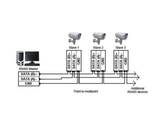
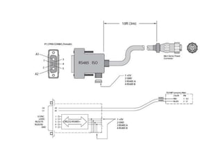
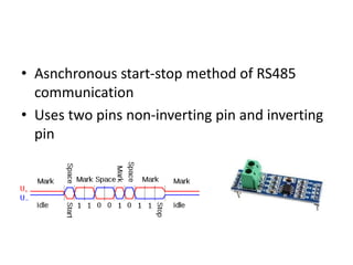
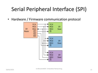
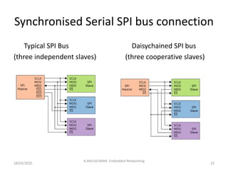
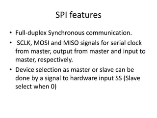
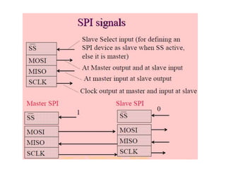
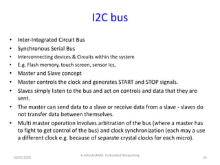
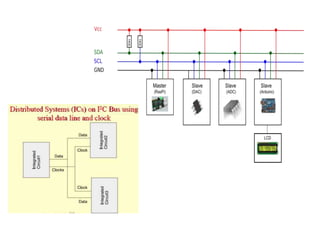
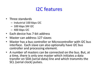
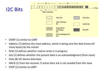
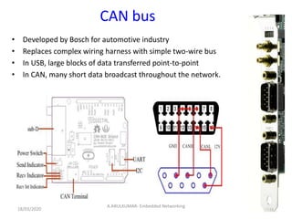
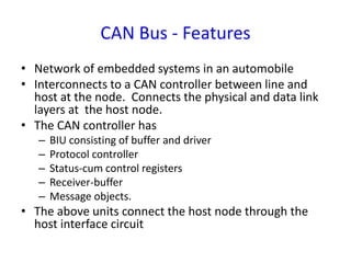
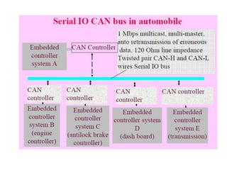
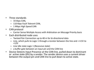
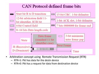
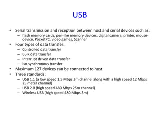
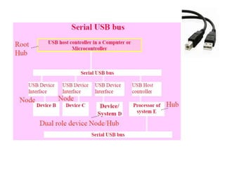
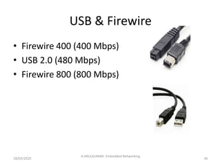
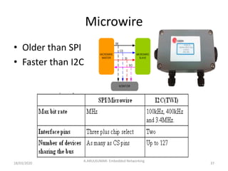
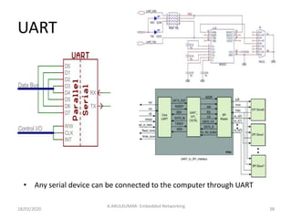
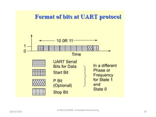
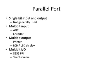
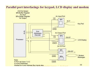
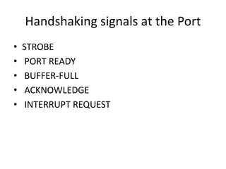
EMBEDDED NETWORKING
A.ARULKUMAR
Asst. Professor
Dept. of Mechatronics Engineering
Kamaraj College of Engg & Tech.
Devices and Communication Buses for
Embedded Networking
• I/O ports – Serial and Parallel
• Interfacing of devices through ports
• Timer
• Real Time Clock
• Networked Embedded Systems
• Serial / Parallel Bus communication protocols
18/03/2020 A.ARULKUMAR- Embedded Networking 2
Hardware units - I/O buses
• Serial Bus examples:
– RS232 (20kBaud)
– CAN (33 kbps)
• Controller Area Network
– Fault tolerant CAN (110
kbps)
– SM I2C (100kbps)
• System Management
– SPI (100 kbps)
• Serial Peripheral Interface
– MicroWire (300 kbps)
– FireWire/IEEE 1394 (400
Mbps, 72m)
– High Speed USB 2.0 (480
Mbps, 25m)
3
A.ARULKUMAR- Embedded Networking
18/03/2020
• Parallel bus examples
• SCSI parallel (40 Mbps),
• Small computer System interface
• Used for interfacing Hard drive,
CDROM, within the system
• Fast SCSI (8M to 80 Mbps) & Ultra
SCSI-3 (8M to 160 Mbps)
• For interfacing more devices to a
processor at higher burst transfer
rates
• PCI
• PCI-X
I/O Port
• To exchange bytes between the processor and external devices
using processor instructions
• Connected using address decoder and system bus
• Addresses of the port-registers used for
– programming the port functions or modes
– reading port status
– writing or reading bytes
• Serial port:
– sync / async,
– input / output / IO
• Parallel port:
– single bit / multibit,
– input / output
18/03/2020
A.ARULKUMAR- Embedded Networking
4
Serial Communication modes
• Half duplex
– Between Modem and telephone line
• Full duplex
– Between Modem and Processor
Serial Communication Protocols
• A protocol is a standard adopted which tells the way in
which the bits of a frame must be sent from a device (or
controller or port or processor) to another device or system
• Protocol identification:
– Type: Sync / Async
– Frame length (variable / fixed)
– Frame contents (Header, address, data, etc.)
– Error control, flow control procedures
• Syncronized communication protocols
– I2C
• Async communication protocols
– RS232
Synchronous serial I/O
• The sender (Master) sends SCLK to the receiver (Slave)
• SCLK can be in the same data line or separate line
• Synchronous serial I/O is used for:
– inter-processor transfers
– streaming data,
– multiprocessor communication,
– writing to CD or hard disk,
– network device output
– serial I/O bus output
– writing to flash memory
• No handshaking. Fixed Clock for synchronized
communication
18/03/2020
A.ARULKUMAR- Embedded Networking
7
Serial communication –
Synchronization methods
18/03/2020
A.ARULKUMAR- Embedded Networking
8
18/03/2020
A.ARULKUMAR- Embedded Networking
9
Asynchronous Serial I/O
• Does not use SCLK but uses handshaking
signals for exchanging data
• Each received byte is not in synchronization.
• Bytes are separated by variable intervals or
phase differences
• E.g. Inputs from Keyboard, mouse, modem
through UART using UART standard format
• Async. Serial ports: E.g. COM1 and COM2
18/03/2020
A.ARULKUMAR- Embedded Networking
10
RS232
• For asynchronous communication between DTE and DCE
(E.g. Modem and UART)
• uses UART standard format for TxD and RxD lines
– logic 1 (Receiver) – 3 V to – 25 V
– logic 0 (Receiver) + 3 V to + 25 V
– logic 1 (Transmitter) – 5 V to – 15 V
– logic 0 (Transmitter) + 5 V to + 15 V
• opposite to that of TTL logic
• wider noise margin to enable long distance communication
• Handshaking signals
– RI, DCD, DSR, DTR, RTS, CTS, DTR
RS232 interface
• Question: What is the difference between Bit rate and Baud rate?
18/03/2020
A.ARULKUMAR- Embedded Networking
14
RS422
• Purpose: To extend RS232
• Point to Point, Multi-drop (RS485 is multi-point as it
can have more than 1 driver)
• Max devices 10 (1 driver and 10 receivers)
• Distance 1500m
• Differential mode signal
• Speed 100 kbps to 10Mbps
• Voltage levels: -6 to +6V
• Mark (1) : Negative voltage
• Space (0) : Positive voltage
RS485
• Used in Industrial control systems for proprietary automation protocols
• Differential signal is used. Hence EMI is suppressed. Used in PLCs
• Voltage level: RS485 driver provides a differential voltage of 1.5V across 54
Ohm load
• Long distance serial communication (1200m) in electrically noisy
environments
• Multiple receivers can be connected in linear bus topology with multi-drop
configuration
• Termination resistors (120 Ohms for twisted pair) are required
• Speed 35 Mbps (10m) 100 kbps (1200m)
• Rule: speed x length < 108
• Master-slave arrangement: master initiates communication
• Full duplex possible with 4 wires
• Can interoperate with RS422
• No specific connector or pinout.
• Asnchronous start-stop method of RS485
communication
• Uses two pins non-inverting pin and inverting
pin
Serial Peripheral Interface (SPI)
• Hardware / Firmware communication protocol
18/03/2020
A.ARULKUMAR- Embedded Networking
21
Synchronised Serial SPI bus connection
Typical SPI Bus Daisychained SPI bus
(three independent slaves) (three cooperative slaves)
18/03/2020
A.ARULKUMAR- Embedded Networking
22
SPI features
• Full-duplex Synchronous communication.
• SCLK, MOSI and MISO signals for serial clock
from master, output from master and input to
master, respectively.
• Device selection as master or slave can be
done by a signal to hardware input SS (Slave
select when 0)
I2C bus
• Inter-Integrated Circuit Bus
• Synchronous Serial Bus
• Interconnecting devices & Circuits within the system
• E.g. Flash memory, touch screen, sensor Ics,
• Master and Slave concept
• Master controls the clock and generates START and STOP signals.
• Slaves simply listen to the bus and act on controls and data that they are
sent.
• The master can send data to a slave or receive data from a slave - slaves do
not transfer data between themselves.
• Multi master operation involves arbitration of the bus (where a master has
to fight to get control of the bus) and clock synchronization (each may a use
a different clock e.g. because of separate crystal clocks for each micro).
18/03/2020
A.ARULKUMAR- Embedded Networking
25
I2C features
• Three standards
– Industrial 100 kbps I2C
– 100 kbps SM I2C
– 400 kbps I2C
• Each device has 7-bit address
• Master can address 127 slaves
• Master has a bus controller or Microcontroller with I2C bus
interface. Each slave can also optionally have I2C bus
controller and processing element.
• A number of masters can be connected on the bus. But, at
a time, there is only one master which initiates a data
transfer on SDA (serial data) line and which transmits the
SCL (serial clock) pulses.
I2C Bits
• START (1) similar to UART
• Address (7) defines the slave address, which is being sent the data frame (of
many bytes) by the master
• R/W (1) defines whether read or write is in progress
• Ack (1) defines whether the present data is an acknowledgment (from slave)
• Data (8) I2C device data byte
• NACK (1) from the receiver. If active then ack is not needed from the slave
• STOP (1) Similar to UART
CAN bus
• Developed by Bosch for automotive industry
• Replaces complex wiring harness with simple two-wire bus
• In USB, large blocks of data transferred point-to-point
• In CAN, many short data broadcast throughout the network.
18/03/2020
A.ARULKUMAR- Embedded Networking
29
CAN Bus - Features
• Network of embedded systems in an automobile
• Interconnects to a CAN controller between line and
host at the node. Connects the physical and data link
layers at the host node.
• The CAN controller has
– BIU consisting of buffer and driver
– Protocol controller
– Status-cum control registers
– Receiver-buffer
– Message objects.
• The above units connect the host node through the
host interface circuit
• Three standards
– 33 kbps CAN,
– 110 kbps Fault Tolerant CAN,
– 1 Mbps High Speed CAN
• CAN protocol
– Carrier Sense Multiple Access with Arbitration on Message Priority basis
• Each distributed node uses
– Twisted Pair Connection up to 40 m for bi-directional data
– Line, which pulls to Logic 1 through a resistor between the line and + 4.5V to
+12V
– Line Idle state Logic 1 (Recessive state)
– a buffer gate between an input pin and the CAN line
• Device Detects Input Presence at the CAN line, pulled down to dominant
or active state (0V) by a sender. The sender device uses a current driver
between the output pin and CAN line to pull down to active state.
• Arbitration concept using Remote Transmission Request (RTR)
– RTR=1: Pkt has data for the destn device
– RTR=0: Pkt has a request for data from destination device
USB
• Serial transmission and reception between host and serial devices such as:
– flash memory cards, pen-like memory devices, digital camera, printer, mouse-
device, PocketPC, video games, Scanner
• Four types of data transfer:
– Controlled data transfer
– Bulk data transfer
– Interrupt driven data transfer
– Iso-synchronous transfer
• Maximum 127 devices can be connected to host
• Three standards:
– USB 1.1 (a low speed 1.5 Mbps 3m channel along with a high speed 12 Mbps
25 meter channel)
– USB 2.0 (high speed 480 Mbps 25m channel)
– Wireless USB (high speed 480 Mbps 3m)
USB & Firewire
• Firewire 400 (400 Mbps)
• USB 2.0 (480 Mbps)
• Firewire 800 (800 Mbps)
18/03/2020
A.ARULKUMAR- Embedded Networking
36
Microwire
• Older than SPI
• Faster than I2C
18/03/2020
A.ARULKUMAR- Embedded Networking
37
UART
• Any serial device can be connected to the computer through UART
18/03/2020
A.ARULKUMAR- Embedded Networking
38
18/03/2020
A.ARULKUMAR- Embedded Networking
39
Parallel Port
• Single bit input and output
– Not generally used
• Multibit input
– ADC
– Encoder
• Multibit output
– Printer
– LCD / LED display
• Multibit I/O
– 8255 PPI
– Touchscreen
Handshaking signals at the Port
• STROBE
• PORT READY
• BUFFER-FULL
• ACKNOWLEDGE
• INTERRUPT REQUEST
Handshaking Procedure for Parallel
Communication
• For input at a port
– Device makes a request to system I/O port – STROBE
– Port sends ack - PORT READY
– Port receives data in receiving buffer
– Port sends INTERRUPT REQUEST to processor indicating receiving-
buffer is full (available for next read)
– Issues INT to processor to enable ISR
• For output at a port
– Processor writes data into transmitting buffer
– Port sends BUFFER FULL to device to inform that buffer is full.
– Device reads message and sends ACKNOWLEDGE
– Port sends INTERRUPT REQUEST to Processor indicating transmitting-
buffer is empty (available for next write)
8255 Programmable Peripheral
Interface
• Four addresses for the PPI port, three for the
ports and one for the control word.
• Three 8-bit ports− port A, B and C.
• Port C programmable to function in bit set
reset mode. Each bit of port C can be set to 1
or reset to 0 by an appropriate control word.
• Alternatively, the ports can be grouped as
Group A (Port A and Port C upper four bits) or
Group B (Port B and Port C lower four bits).
Parallel – ISA Bus
• 16-bit and 8-bit ISA slots
Parallel communication - PCI
• Peripheral Component Interconnect
• 32 pin interface for connecting additional hardware to a system
• 33 MHz speed
• E.g. Add-on boards, Processor / memory systems
• Not generally used in Embedded systems
18/03/2020
A.ARULKUMAR- Embedded Networking
46
Parallel communication – PCI X
• Peripheral component interconnect Extended
• 64 bit operation
• 66 / 100 / 133 MHz speed
18/03/2020
A.ARULKUMAR- Embedded Networking
47
Parallel communication - SCSI
• Small Computer System Interface
• Parallel interface standard for connecting peripherals such as
printers, hard disk, CD ROM drive, etc.
18/03/2020
A.ARULKUMAR- Embedded Networking
48
THANK YOU

Embedded networking

  • 1.
    EMBEDDED NETWORKING A.ARULKUMAR Asst. Professor Dept.of Mechatronics Engineering Kamaraj College of Engg & Tech.
  • 2.
    Devices and CommunicationBuses for Embedded Networking • I/O ports – Serial and Parallel • Interfacing of devices through ports • Timer • Real Time Clock • Networked Embedded Systems • Serial / Parallel Bus communication protocols 18/03/2020 A.ARULKUMAR- Embedded Networking 2
  • 3.
    Hardware units -I/O buses • Serial Bus examples: – RS232 (20kBaud) – CAN (33 kbps) • Controller Area Network – Fault tolerant CAN (110 kbps) – SM I2C (100kbps) • System Management – SPI (100 kbps) • Serial Peripheral Interface – MicroWire (300 kbps) – FireWire/IEEE 1394 (400 Mbps, 72m) – High Speed USB 2.0 (480 Mbps, 25m) 3 A.ARULKUMAR- Embedded Networking 18/03/2020 • Parallel bus examples • SCSI parallel (40 Mbps), • Small computer System interface • Used for interfacing Hard drive, CDROM, within the system • Fast SCSI (8M to 80 Mbps) & Ultra SCSI-3 (8M to 160 Mbps) • For interfacing more devices to a processor at higher burst transfer rates • PCI • PCI-X
  • 4.
    I/O Port • Toexchange bytes between the processor and external devices using processor instructions • Connected using address decoder and system bus • Addresses of the port-registers used for – programming the port functions or modes – reading port status – writing or reading bytes • Serial port: – sync / async, – input / output / IO • Parallel port: – single bit / multibit, – input / output 18/03/2020 A.ARULKUMAR- Embedded Networking 4
  • 5.
    Serial Communication modes •Half duplex – Between Modem and telephone line • Full duplex – Between Modem and Processor
  • 6.
    Serial Communication Protocols •A protocol is a standard adopted which tells the way in which the bits of a frame must be sent from a device (or controller or port or processor) to another device or system • Protocol identification: – Type: Sync / Async – Frame length (variable / fixed) – Frame contents (Header, address, data, etc.) – Error control, flow control procedures • Syncronized communication protocols – I2C • Async communication protocols – RS232
  • 7.
    Synchronous serial I/O •The sender (Master) sends SCLK to the receiver (Slave) • SCLK can be in the same data line or separate line • Synchronous serial I/O is used for: – inter-processor transfers – streaming data, – multiprocessor communication, – writing to CD or hard disk, – network device output – serial I/O bus output – writing to flash memory • No handshaking. Fixed Clock for synchronized communication 18/03/2020 A.ARULKUMAR- Embedded Networking 7
  • 8.
    Serial communication – Synchronizationmethods 18/03/2020 A.ARULKUMAR- Embedded Networking 8
  • 9.
  • 10.
    Asynchronous Serial I/O •Does not use SCLK but uses handshaking signals for exchanging data • Each received byte is not in synchronization. • Bytes are separated by variable intervals or phase differences • E.g. Inputs from Keyboard, mouse, modem through UART using UART standard format • Async. Serial ports: E.g. COM1 and COM2 18/03/2020 A.ARULKUMAR- Embedded Networking 10
  • 12.
    RS232 • For asynchronouscommunication between DTE and DCE (E.g. Modem and UART) • uses UART standard format for TxD and RxD lines – logic 1 (Receiver) – 3 V to – 25 V – logic 0 (Receiver) + 3 V to + 25 V – logic 1 (Transmitter) – 5 V to – 15 V – logic 0 (Transmitter) + 5 V to + 15 V • opposite to that of TTL logic • wider noise margin to enable long distance communication • Handshaking signals – RI, DCD, DSR, DTR, RTS, CTS, DTR
  • 14.
    RS232 interface • Question:What is the difference between Bit rate and Baud rate? 18/03/2020 A.ARULKUMAR- Embedded Networking 14
  • 15.
    RS422 • Purpose: Toextend RS232 • Point to Point, Multi-drop (RS485 is multi-point as it can have more than 1 driver) • Max devices 10 (1 driver and 10 receivers) • Distance 1500m • Differential mode signal • Speed 100 kbps to 10Mbps • Voltage levels: -6 to +6V • Mark (1) : Negative voltage • Space (0) : Positive voltage
  • 17.
    RS485 • Used inIndustrial control systems for proprietary automation protocols • Differential signal is used. Hence EMI is suppressed. Used in PLCs • Voltage level: RS485 driver provides a differential voltage of 1.5V across 54 Ohm load • Long distance serial communication (1200m) in electrically noisy environments • Multiple receivers can be connected in linear bus topology with multi-drop configuration • Termination resistors (120 Ohms for twisted pair) are required • Speed 35 Mbps (10m) 100 kbps (1200m) • Rule: speed x length < 108 • Master-slave arrangement: master initiates communication • Full duplex possible with 4 wires • Can interoperate with RS422 • No specific connector or pinout.
  • 20.
    • Asnchronous start-stopmethod of RS485 communication • Uses two pins non-inverting pin and inverting pin
  • 21.
    Serial Peripheral Interface(SPI) • Hardware / Firmware communication protocol 18/03/2020 A.ARULKUMAR- Embedded Networking 21
  • 22.
    Synchronised Serial SPIbus connection Typical SPI Bus Daisychained SPI bus (three independent slaves) (three cooperative slaves) 18/03/2020 A.ARULKUMAR- Embedded Networking 22
  • 23.
    SPI features • Full-duplexSynchronous communication. • SCLK, MOSI and MISO signals for serial clock from master, output from master and input to master, respectively. • Device selection as master or slave can be done by a signal to hardware input SS (Slave select when 0)
  • 25.
    I2C bus • Inter-IntegratedCircuit Bus • Synchronous Serial Bus • Interconnecting devices & Circuits within the system • E.g. Flash memory, touch screen, sensor Ics, • Master and Slave concept • Master controls the clock and generates START and STOP signals. • Slaves simply listen to the bus and act on controls and data that they are sent. • The master can send data to a slave or receive data from a slave - slaves do not transfer data between themselves. • Multi master operation involves arbitration of the bus (where a master has to fight to get control of the bus) and clock synchronization (each may a use a different clock e.g. because of separate crystal clocks for each micro). 18/03/2020 A.ARULKUMAR- Embedded Networking 25
  • 27.
    I2C features • Threestandards – Industrial 100 kbps I2C – 100 kbps SM I2C – 400 kbps I2C • Each device has 7-bit address • Master can address 127 slaves • Master has a bus controller or Microcontroller with I2C bus interface. Each slave can also optionally have I2C bus controller and processing element. • A number of masters can be connected on the bus. But, at a time, there is only one master which initiates a data transfer on SDA (serial data) line and which transmits the SCL (serial clock) pulses.
  • 28.
    I2C Bits • START(1) similar to UART • Address (7) defines the slave address, which is being sent the data frame (of many bytes) by the master • R/W (1) defines whether read or write is in progress • Ack (1) defines whether the present data is an acknowledgment (from slave) • Data (8) I2C device data byte • NACK (1) from the receiver. If active then ack is not needed from the slave • STOP (1) Similar to UART
  • 29.
    CAN bus • Developedby Bosch for automotive industry • Replaces complex wiring harness with simple two-wire bus • In USB, large blocks of data transferred point-to-point • In CAN, many short data broadcast throughout the network. 18/03/2020 A.ARULKUMAR- Embedded Networking 29
  • 30.
    CAN Bus -Features • Network of embedded systems in an automobile • Interconnects to a CAN controller between line and host at the node. Connects the physical and data link layers at the host node. • The CAN controller has – BIU consisting of buffer and driver – Protocol controller – Status-cum control registers – Receiver-buffer – Message objects. • The above units connect the host node through the host interface circuit
  • 32.
    • Three standards –33 kbps CAN, – 110 kbps Fault Tolerant CAN, – 1 Mbps High Speed CAN • CAN protocol – Carrier Sense Multiple Access with Arbitration on Message Priority basis • Each distributed node uses – Twisted Pair Connection up to 40 m for bi-directional data – Line, which pulls to Logic 1 through a resistor between the line and + 4.5V to +12V – Line Idle state Logic 1 (Recessive state) – a buffer gate between an input pin and the CAN line • Device Detects Input Presence at the CAN line, pulled down to dominant or active state (0V) by a sender. The sender device uses a current driver between the output pin and CAN line to pull down to active state.
  • 33.
    • Arbitration conceptusing Remote Transmission Request (RTR) – RTR=1: Pkt has data for the destn device – RTR=0: Pkt has a request for data from destination device
  • 34.
    USB • Serial transmissionand reception between host and serial devices such as: – flash memory cards, pen-like memory devices, digital camera, printer, mouse- device, PocketPC, video games, Scanner • Four types of data transfer: – Controlled data transfer – Bulk data transfer – Interrupt driven data transfer – Iso-synchronous transfer • Maximum 127 devices can be connected to host • Three standards: – USB 1.1 (a low speed 1.5 Mbps 3m channel along with a high speed 12 Mbps 25 meter channel) – USB 2.0 (high speed 480 Mbps 25m channel) – Wireless USB (high speed 480 Mbps 3m)
  • 36.
    USB & Firewire •Firewire 400 (400 Mbps) • USB 2.0 (480 Mbps) • Firewire 800 (800 Mbps) 18/03/2020 A.ARULKUMAR- Embedded Networking 36
  • 37.
    Microwire • Older thanSPI • Faster than I2C 18/03/2020 A.ARULKUMAR- Embedded Networking 37
  • 38.
    UART • Any serialdevice can be connected to the computer through UART 18/03/2020 A.ARULKUMAR- Embedded Networking 38
  • 39.
  • 40.
    Parallel Port • Singlebit input and output – Not generally used • Multibit input – ADC – Encoder • Multibit output – Printer – LCD / LED display • Multibit I/O – 8255 PPI – Touchscreen
  • 42.
    Handshaking signals atthe Port • STROBE • PORT READY • BUFFER-FULL • ACKNOWLEDGE • INTERRUPT REQUEST
  • 43.
    Handshaking Procedure forParallel Communication • For input at a port – Device makes a request to system I/O port – STROBE – Port sends ack - PORT READY – Port receives data in receiving buffer – Port sends INTERRUPT REQUEST to processor indicating receiving- buffer is full (available for next read) – Issues INT to processor to enable ISR • For output at a port – Processor writes data into transmitting buffer – Port sends BUFFER FULL to device to inform that buffer is full. – Device reads message and sends ACKNOWLEDGE – Port sends INTERRUPT REQUEST to Processor indicating transmitting- buffer is empty (available for next write)
  • 44.
    8255 Programmable Peripheral Interface •Four addresses for the PPI port, three for the ports and one for the control word. • Three 8-bit ports− port A, B and C. • Port C programmable to function in bit set reset mode. Each bit of port C can be set to 1 or reset to 0 by an appropriate control word. • Alternatively, the ports can be grouped as Group A (Port A and Port C upper four bits) or Group B (Port B and Port C lower four bits).
  • 45.
    Parallel – ISABus • 16-bit and 8-bit ISA slots
  • 46.
    Parallel communication -PCI • Peripheral Component Interconnect • 32 pin interface for connecting additional hardware to a system • 33 MHz speed • E.g. Add-on boards, Processor / memory systems • Not generally used in Embedded systems 18/03/2020 A.ARULKUMAR- Embedded Networking 46
  • 47.
    Parallel communication –PCI X • Peripheral component interconnect Extended • 64 bit operation • 66 / 100 / 133 MHz speed 18/03/2020 A.ARULKUMAR- Embedded Networking 47
  • 48.
    Parallel communication -SCSI • Small Computer System Interface • Parallel interface standard for connecting peripherals such as printers, hard disk, CD ROM drive, etc. 18/03/2020 A.ARULKUMAR- Embedded Networking 48
  • 49.