Downloaded 114 times

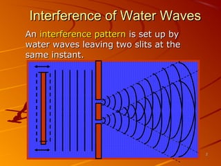
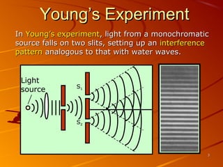
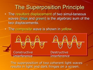
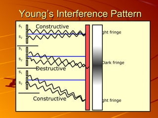
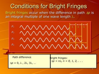
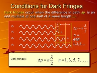
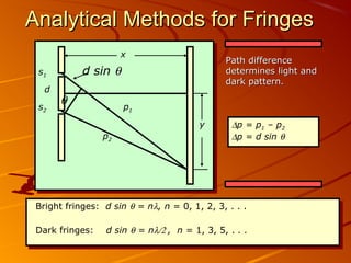
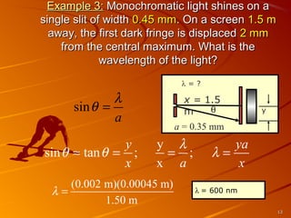

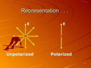
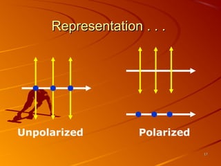
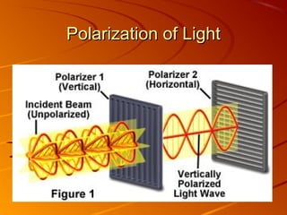
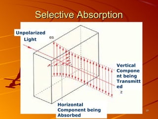
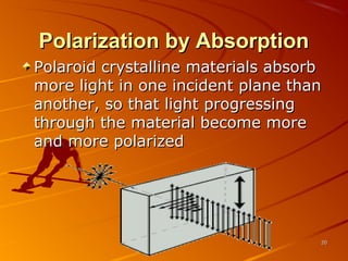
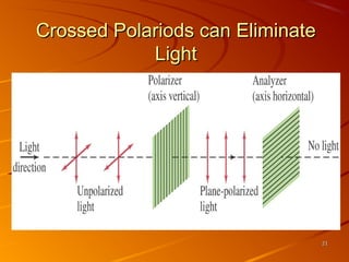
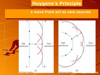
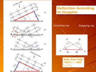
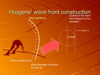

The document discusses several key properties of light: 1) Interference and polarization of light are examined through experiments like Young's slits and using polarizers. Interference creates light and dark fringes depending on the path difference between waves. 2) Huygens' principle is introduced as explaining how secondary wavelets propagate light in a manner consistent with laws of reflection and refraction. Each point on a wavefront acts as a secondary source. 3) Polarization occurs when unpolarized light passes through a filter, causing vibrations of the electric field to lie in one plane rather than randomly oriented planes. Crossed polarizers can eliminate transmitted light.


