Download to read offline
![IOSR Journal of Electrical and Electronics Engineering (IOSR-JEEE)
e-ISSN: 2278-1676,p-ISSN: 2320-3331, Volume 5, Issue 3 (Mar. - Apr. 2013), PP 49-54
www.iosrjournals.org
www.iosrjournals.org 49 | Page
Electronic Load Controller for Self Exited Induction Generator
Using Fuzzy Logic Controller
Yellaiah.Ponnam 1,
P.Ravi Kumar 2,
V.Varun Kumar 3
Asst.Professor Dept. of EEE Sri Indu College of Engineering &Technology(Autonomous), Affiliated to JNTU
Hyderabad, India
Pursuing B.Tech Dept. of EEE Gurunanak Institutions Technical Campus(formerly GuruNanak Engineering
College) Hyderabad, India
Assoc.Professor Dept. of EEE GuruNanak Institutions Technical Campus(formerly GuruNanak Engineering
College) Hyderabad, India
Abstract: This paper deals with the electronic load controller for self exited induction generator using fuzzy
logic controller. The self-excited induction generators (SEIGs) are considered to be well suited for generating
electricity by means of conventional energy sources and for supplying electrical energy in remote and rural
areas. Induction generators have many advantages such as cost, reduced maintenance, rugged, and simple
construction, brushless rotor (squirrel cage). A three phase induction generator can be operated on a delta
connection for supplying single phase loads. The main disadvantage of SEIG has is that it poor voltage
regulation, and its value depends on the prime mover speed, capacitance, load current and power factor of the
load. The electronic load controller (ELC) can be used for maintaining constant voltage and frequency of SEIG
with variable consumer load driven by constant prime mover. This paper presents the simulation design and
implementation of ELC using fuzzy logic method for an SEIG feeding single-phase load. The ELC consist of a
rectifier, IGBT as a chopper switch, PI controller, voltage sensor, and resistive dump load in which power
consumption was varied through the duty cycle of the chopper. However an ELC consist of electronics system,
in general, has complex nonlinear model with parameter variation problem, and the control need to be very
fast. The fuzzy logic based controller gives nonlinear control with fast response and virtually no overshoot. The
simulation of ELC for self exited induction generator is carried out on MATLAB/SIMULINK. By this proposed
ELC using FLC for SEIG we can maintain the constant voltage and frequency of SEIG with variable consumer
load.
Keywords— Electronic load controller (ELC), Self excited induction generator (SEIG), Fuzzy logic controller.
I. Introduction
Recently, most of the electricity is generated making use of fossil fuels (coal, oil, and natural gas).
These fossil fuels are limited and will run out in the future. Fossil fuels are a nonrenewable energy source and
they have continuously degraded the environmental conditions. In such a situation researchers are forced to
make effort to make use of new and renewable energy sources in an economical and safe way. Among electrical
generation using the renewable sources, micro hydro generation systems are an attractive alternative for remote
locations where an consider economical, robust and require minimal maintenance and are likely to be managed
by un- skilled operators, because they are usually installed remote from any maintenance facilities.
The squirrel cage induction machine with capacitive self excitation, known as self-excited induction
generators (SEIGs) are considered as an alternative to the well-developed synchronous generators. Induction
generators are widely used for micro-hydro powered electric generation, especially in remote and isolated areas,
because they do not need an external power supply to produce the excitation magnetic field. Furthermore,
induction generators have more advantages such as low cost, reduced maintenance, rugged and simple
construction, brushless rotor (squirrel cage), good over-speed capability, and inherent protraction against short
circuit [1] .Keeping the voltage and frequency of SEIG constant in spite of the change in load, can be done by
regulating the capacitance value or by controlling the speed of the prime movers. One alternative for supplying
single phase loads widely used in remote and rural areas is using three-phase induction generator. It is used to
supply the single phase loads by using the connection delta. If the induction generator is used to supply single
phase with a constant load, the ELC could be applied to maintain constant power output SEIG, for this purpose
the dump load must be connected in parallel with the consumer load so that the total power load is generated by
the SEIG is constant . The amount of power that flowing into the dump load is controlled by the electronic load
controller (ELC) [4]-[5].](https://image.slidesharecdn.com/j0534954-140503011531-phpapp02/85/Electronic-Load-Controller-for-Self-Exited-Induction-Generator-Using-Fuzzy-Logic-Controller-1-320.jpg)
![IOSR Journal of Electrical and Electronics Engineering (IOSR-JEEE)
e-ISSN: 2278-1676,p-ISSN: 2320-3331, Volume 5, Issue 3 (Mar. - Apr. 2013), PP 49-54
www.iosrjournals.org
www.iosrjournals.org 49 | Page
Electronic Load Controller for Self Exited Induction Generator
Using Fuzzy Logic Controller
Yellaiah.Ponnam 1,
P.Ravi Kumar 2,
V.Varun Kumar 3
Asst.Professor Dept. of EEE Sri Indu College of Engineering &Technology(Autonomous), Affiliated to JNTU
Hyderabad, India
Pursuing B.Tech Dept. of EEE Gurunanak Institutions Technical Campus(formerly GuruNanak Engineering
College) Hyderabad, India
Assoc.Professor Dept. of EEE GuruNanak Institutions Technical Campus(formerly GuruNanak Engineering
College) Hyderabad, India
Abstract: This paper deals with the electronic load controller for self exited induction generator using fuzzy
logic controller. The self-excited induction generators (SEIGs) are considered to be well suited for generating
electricity by means of conventional energy sources and for supplying electrical energy in remote and rural
areas. Induction generators have many advantages such as cost, reduced maintenance, rugged, and simple
construction, brushless rotor (squirrel cage). A three phase induction generator can be operated on a delta
connection for supplying single phase loads. The main disadvantage of SEIG has is that it poor voltage
regulation, and its value depends on the prime mover speed, capacitance, load current and power factor of the
load. The electronic load controller (ELC) can be used for maintaining constant voltage and frequency of SEIG
with variable consumer load driven by constant prime mover. This paper presents the simulation design and
implementation of ELC using fuzzy logic method for an SEIG feeding single-phase load. The ELC consist of a
rectifier, IGBT as a chopper switch, PI controller, voltage sensor, and resistive dump load in which power
consumption was varied through the duty cycle of the chopper. However an ELC consist of electronics system,
in general, has complex nonlinear model with parameter variation problem, and the control need to be very
fast. The fuzzy logic based controller gives nonlinear control with fast response and virtually no overshoot. The
simulation of ELC for self exited induction generator is carried out on MATLAB/SIMULINK. By this proposed
ELC using FLC for SEIG we can maintain the constant voltage and frequency of SEIG with variable consumer
load.
Keywords— Electronic load controller (ELC), Self excited induction generator (SEIG), Fuzzy logic controller.
I. Introduction
Recently, most of the electricity is generated making use of fossil fuels (coal, oil, and natural gas).
These fossil fuels are limited and will run out in the future. Fossil fuels are a nonrenewable energy source and
they have continuously degraded the environmental conditions. In such a situation researchers are forced to
make effort to make use of new and renewable energy sources in an economical and safe way. Among electrical
generation using the renewable sources, micro hydro generation systems are an attractive alternative for remote
locations where an consider economical, robust and require minimal maintenance and are likely to be managed
by un- skilled operators, because they are usually installed remote from any maintenance facilities.
The squirrel cage induction machine with capacitive self excitation, known as self-excited induction
generators (SEIGs) are considered as an alternative to the well-developed synchronous generators. Induction
generators are widely used for micro-hydro powered electric generation, especially in remote and isolated areas,
because they do not need an external power supply to produce the excitation magnetic field. Furthermore,
induction generators have more advantages such as low cost, reduced maintenance, rugged and simple
construction, brushless rotor (squirrel cage), good over-speed capability, and inherent protraction against short
circuit [1] .Keeping the voltage and frequency of SEIG constant in spite of the change in load, can be done by
regulating the capacitance value or by controlling the speed of the prime movers. One alternative for supplying
single phase loads widely used in remote and rural areas is using three-phase induction generator. It is used to
supply the single phase loads by using the connection delta. If the induction generator is used to supply single
phase with a constant load, the ELC could be applied to maintain constant power output SEIG, for this purpose
the dump load must be connected in parallel with the consumer load so that the total power load is generated by
the SEIG is constant . The amount of power that flowing into the dump load is controlled by the electronic load
controller (ELC) [4]-[5].](https://image.slidesharecdn.com/j0534954-140503011531-phpapp02/75/Electronic-Load-Controller-for-Self-Exited-Induction-Generator-Using-Fuzzy-Logic-Controller-1-2048.jpg)
![Electronic Load Controller for Self Exited Induction Generator Using Fuzzy Logic Controller
www.iosrjournals.org 50 | Page
Various controllers for SEIG have been reported in literature. T.Chandra Sekhar et.al. [2] Proposed different
voltage regulation schemes such as power electronic controller, electronic load controller and magnetic
amplifier (saturable core reactor). Bhim Singh et.al [5] has been developed an ELC for two winding single
phase SEIG. Juan M.Ramirez et.al [3] proposed an ELC with anti parallel insulated-gate bipolar transistor
(IGBT) switches are used to control dump load connection and disconnection. D.K.Palwalia et.al [6] present
design and implementation of Digital Signal Processor (DSP) based induction generator controller (IGC) for
single phase SEIG. Sarsing Gao et al [1] present analysis and the design of a microcontroller (PIC 18F252)
based SEIG-ELC. A PI controller is used to provide proper control without steady state errors or instability.
This paper presents the simulation design and implementation of Electronic Load Controller (ELC) for
a Self Excited Induction Generator (SEIG) using Fuzzy Logic Controller. The SEIG using three phase induction
generator feeding single phase loads. In addition to the PI controller we are using FLC. The mains reasons of
using fuzzy logic controller to gives nonlinear control with fast response and virtually no overshoot. The
proposed ELC will be simulated under variable consumer load and resistive load as the dump load in ELC.
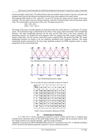
II. System Description
Fig.1 SEIG system configuration control strategy of a chopper switch in a six – pulse diode bridge ELC
using FLC.
Fig.1 shows the isolated Pico hydro generating system that consists of an SEIG, excitation capacitor, consumer
loads, and conventional ELC (six-pulse diode rectifier along with the chopper). The diode bridge is used to
convert ac terminal voltage of SEIG to dc voltage. The output dc voltage has the ripples, which should be
filtered, and therefore, a filtering capacitor is used to smoothen the dc voltage. An insulated gate bipolar
junction transistor (IGBT) is used as a chopper switch providing the variable dc voltage across the auxiliary
load. When the chopper is switched ON, the current flows through its auxiliary load and consume the difference
power (difference of generated power and consumer load power) that results in a constant load on the SEIG, and
hence, constant voltage and frequency at the varying consumer loads. The duty cycle of the chopper is varied by
an analog-controller-based proportional–integral (PI) regulator and Fuzzy Logic Controller. The sensed terminal
voltage is compared with reference voltage and error signal is processed through PI controller. The output of PI
controller is given to fuzzy logic controller and it generates outputs and these are compared with fixed frequency
saw tooth wave to generate the varying duty cycle switching signal for the chopper switch. According to the
principle of operation of the system, the suitable value of capacitors is connected to generate rated voltage at
desired power [9]. The input power of the SEIG is held constant at varying consumer loads. Thus, SEIG feeds
two loads (consumer load + ELC) in parallel such that the total power is constant
PGEN=PELC +PLOAD
Where PGEN is generated power by the SEIG (which should be kept constant), PLOAD is consumed power by
consumers, and PELC is the power absorbed by the ELC.
III. Fuzzy Logic Controller
A fuzzy logic controller consists of four main components as fuzzification, rule base, inference
mechanism and defuzzification. The fuzzification converts its inputs into fuzzy values with membership
functions in the form of triangle, trapezoid, bell or other appropriate forms expressed by the fuzzy linguistic
variables. The rule base contains the expert’s linguistic descriptions expressed in the form of logical
implications such as IF x is positive THEN y is big. The inference mechanism evaluates fuzzy information to](https://image.slidesharecdn.com/j0534954-140503011531-phpapp02/85/Electronic-Load-Controller-for-Self-Exited-Induction-Generator-Using-Fuzzy-Logic-Controller-2-320.jpg)
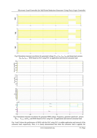
![Electronic Load Controller for Self Exited Induction Generator Using Fuzzy Logic Controller
www.iosrjournals.org 54 | Page
controller responds and current flowing through ELC is reduced to control total generated power at the
generator terminal constant. Availability of the sufficient excitation capacitor keeps the constant voltage at the
generator terminal. Here, an observation is made that because of the ELC using FLC the system response
increases and overshoots in the system due to sudden change in load is reduced. Another observation is made
that by using the FLC based ELC for SEIG the generator power , frequency and speed is maintained constant
with variation of consumer load.
VII. Conclusion
Electronic load controller for a self excited induction generator using fuzzy logic controller has been
developed on the basis of simulation using standard software MATLAB. The FLC based ELC for SEIG has
given constant power and constant frequency in the operation of self exited induction generator at varying
consumer loads. And the system response is also fast compared to the ELC using PI controller and overshoots
reduced by using fuzzy logic controller.
References
[1] R. C. Bansal, “Three-Phase Self-Excited Induction Generators: An Overview,” IEEE Transactions on Energy Conversion, Vol. 20,
No. 2, pp. 292-299 June 2005.
[2] Chandra, T.S., Bishnu, P.M., Voltage Regulators for Self Excited Induction Generator, IEEE Transactions on Energy Conversion,
Vol.20, no. 4, , pp 460÷463,April 2004.
[3] Juan M. Ramirez and Emmanuel Torres M., “An electronic load controller for self excited induction generators” in IEEE PES
General Meeting, June 24-28, 2007.
[4] Sarsing Gao, S. S. Murthy, G. Bhubaneswar, and M. Sree Lalitha Gayathri, “Design of a Microcontroller Based Electronic Load
Controller for a Self Excited Induction Generator Supplying Single - Phase Loads,” Journal of Power Electronics, Vol. 10, No.4,
pp.444- 449, 2010.
[5] Bhim Singh, S.S. Murthy & Sushma Gupta ,”An Electronic Voltage and Frequency Controller for Single-Phase Self-Excited
Induction Generators for Pico Hydro Applications”,IEEE PEDS, pp 240-245,2005.
[6] Palwalia, D.K.; Singh, S.P.; , “Design and implementation of induction generator controller for single phase self excited induction
generator,” Industrial Electronics and Applications, 2008. ICIEA 2008. 3rd IEEE Conference on , vol., no., pp.400-404, 3-5 June
2008.
[7] Bhim Singh, S.S. Murthy & Sushma Gupta ,”An Electronic Voltage and Frequency Controller for Single-Phase Self-Excited
Induction Generators for Pico Hydro Applications”,IEEE PEDS, pp 240-245,2005.
[8] B. Singh, S. S. Murthy and S. Gupta, “Analysis and Implementation of an Electronic Load Controller for a Self- Excited Induction
Generator,” IEE Proceedings Generation Transmission and Distribution, Vol. 151, No.1, pp. 51-60,January 2004.
[9] B. Singh, S. S. Murthy, and S. Gupta, “STATCOM based voltage regulator for isolated asynchronous generator feeding non-linear
loads,” IEEE Trans. Ind. Electron., vol. 53, no. 5, pp. 1437–1452, Oct. 2006.
ABOUT AUTHORS:
Ponnam.Yellaiah, Asst.Professor
Received M.Tech degree in Control Systems in Dept. of Electrical and Electronics
Engineering, JNTU Hyderabad. He is currently working as Asst. Professor in EEE
Department of Sri Indu College of Engineering &Technology(Autonomous) ,Hyderabad, His
is doing currently research in control system, Power electronics, FACTS and PLCs
Ravi Kumar. Pendli, Pursuing B.Tech
Pursuing B.Tech degree in Electrical and Electronics Engineering from Guru Nanak
Institutions Technical Campus (formerly Guru Nanak Engineering College), JNTU Hyderabad.
Area of interests include Power Systems Control Systems and Renewable Energy Systems.
Varun Kumar Vattikuti, Assoc. Professor
Received M.Tech degree in Electrical Power Systems in Electrical and Electronics
Engineering from the University of JNTU Hyderabad. He is currently working as
Assoc.Professor in EEE Department in Guru Nanak Institutions Technical Campus (Formerly
Guru Nanak Engineering College), Hyderabad, His currently research interests include
control system, Power electronics,](https://image.slidesharecdn.com/j0534954-140503011531-phpapp02/85/Electronic-Load-Controller-for-Self-Exited-Induction-Generator-Using-Fuzzy-Logic-Controller-6-320.jpg)

This document describes a simulation of an electronic load controller (ELC) for a self-excited induction generator (SEIG) using a fuzzy logic controller (FLC). SEIGs are well-suited for distributed generation but have variable voltage regulation that depends on load conditions. The proposed ELC uses a diode rectifier and IGBT chopper with a resistive dump load to maintain constant voltage and frequency at the SEIG terminals despite varying consumer load. A FLC is developed with error and change in error as inputs and duty cycle as the output to control the chopper. Simulation results in MATLAB/Simulink show the ELC with FLC maintains constant generator power, frequency and speed with changes in consumer load