Downloaded 12 times


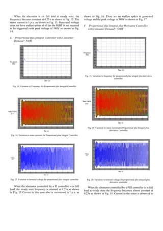
![be at 1p.u. as shown in Fig. 19. The voltage in line A does not
have any spikes and the peak voltage is 340V as rated as
shown in Fig. 20. The results been discussed so far have been
tabulated in Table I and Table II for a better insight.
TABLE I. RESULTS OF VARIOUS CONTROLLER CONFIGURATIONS FOR
CONSUMER DEMAND = 0 KW
CONSUMER DEMAND = 0 kW
Type of Controller Results
P
-Perturbation in frequency is
from 50-50.05 Hz in steady-
state.
-Peak stator current is slightly
above 1pu.
-Peak value of voltage is 370
Volts.
-Steady-state is attained in
0.29 sec.
PI
-Perturbation in frequency in
steady-state is of relatively
lower amplitude.
-Peak stator current is slightly
above 1pu.
-Peak value of voltage is 370
Volts.
-Steady-state is attained in
0.29 sec.
PID
-Perturbation in frequency in
steady-state is reduced
further.
-Peak stator current is slightly
more than 1pu.
-Peak value of voltage is 370
Volts.
-Steady-state is attained in
0.26 sec.
TABLE II. RESULTS OF VARIOUS CONTROLLER CONFIGURATIONS FOR
CONSUMER DEMAND = 50 KW
CONSUMER DEMAND = 50 kW
Type of Controller Results
P
-Frequency is maintained at
50Hz in steady-state.
-Stator current is maintained
at 1pu.
-Peak value of voltage is 340
Volts with no sudden spikes.
-Steady-state is attained in
0.25 sec.
PI
- Frequency is maintained at
50Hz in steady-state.
- Current is also maintained
at 1pu.
-Peak value of voltage is 340
Volts without any sudden
spikes.
-Steady-state is attained in
0.25 sec.
PID
- Frequency is maintained at
50Hz in steady-state.
- Current is also maintained
at 1pu.
-Peak value of voltage is 340
Volts without any sudden
spikes.
-Steady-state is attained in
0.25 sec.
VII. CONCLUSION
The work presents the steady-state analysis of electronic
load controller for three phase synchronous generator. The
result is obtained based on the equation which assumes linear
relationship of the consumer demand and frequency. It also
assumes linear relation between change in frequency and the
dump load connected. The PID based electronic controller is
faster as compared to Proportional and PI controller. The ELC
is achieving its objective to control the frequency but the per
phase peak voltage is rising up-to 370V at no load due to AVR
action and the stator current of the generator is exceeding
1p.u.
REFERENCES
[1] Anurag Yadav, et al, “A Fuzzy Logic based Electronic Load Controller
for Three Phase Alternator”, International Journal of Emerging
Technology and Advanced Engineering, Vol. 5, Issue 3, pp. 514-520,
March 2015.
[2] Das Dibyendu, M.Tech dissertation Work On, “Steady-State analysis of
Electronic Load Controller for Three Phase Alternator” , Alternate
Hydro Energy Centre, Indian Institute of Technology Roorkee, 2011.
[3] Singh B., et al, “Analysis and design of ELC for SEIG”, IEEE
Transactions on energy conversion, Vol. 21, No. 21, pp 285-293, March
2006.
[4] Murthy S.S., et al, “A novel digital control technique for ELC for SEIG
based micro hydel power generation”, IEEE International Conference on
Power Electronics, drives and energy systems, pp 1-5, 12-15 dec, 2006.
[5] Ramirez J.M, et al, “An electronic load controller for self-excited
induction generator”, IEEE Transactions on energy conversion, Vol. 22,
No. 2, pp 1-8, 2007
[6] Rajagopal V., et al, “Electronic load controller for isolated asynchronous
generator in pico hydropower generation”, Conference paper,
Department of Electrical Engineering, Indian Institute of Technology
Roorkee, 2010.](https://image.slidesharecdn.com/3a5970f4-82ec-4254-8807-0c66502ad2de-161124200353/85/Steady-State-Analysis-of-Electronic-Load-Controller-6-320.jpg)

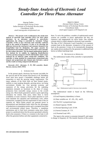
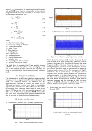
1) The document presents a steady-state analysis of an electronic load controller (ELC) for a three-phase alternator used in micro-hydro applications. Mathematical and Simulink models of the ELC are developed and analyzed for proportional, proportional-integral, and proportional-integral-derivative controllers. 2) Simulation results show that PID control reduces frequency variation most compared to P and PI control. With no consumer load, voltage spikes up to 370V but current remains slightly above rated. With full consumer load, all controllers maintain 50Hz frequency and rated voltage/current. 3) In conclusion, the PID ELC controls frequency faster than P and PI controllers but voltage rises too high at no load due to