Download as PDF, PPTX


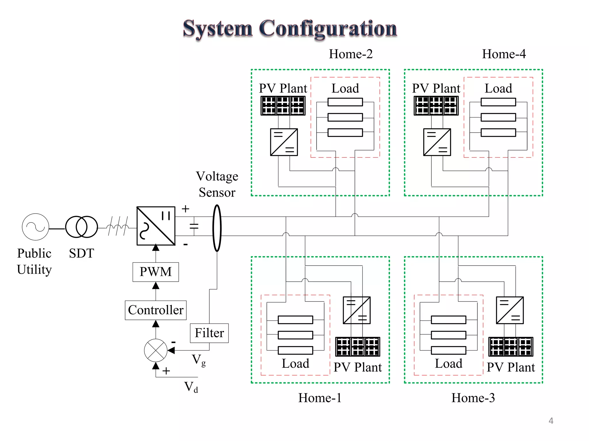
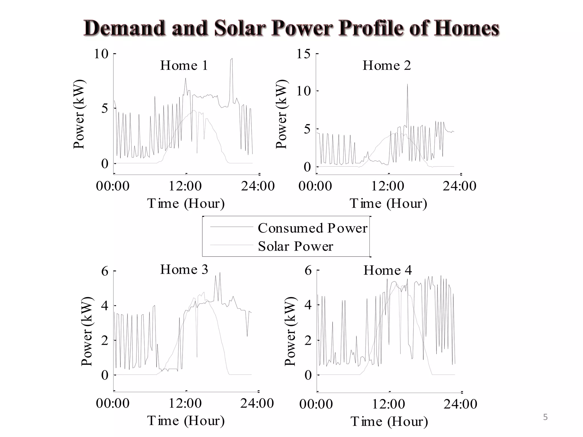
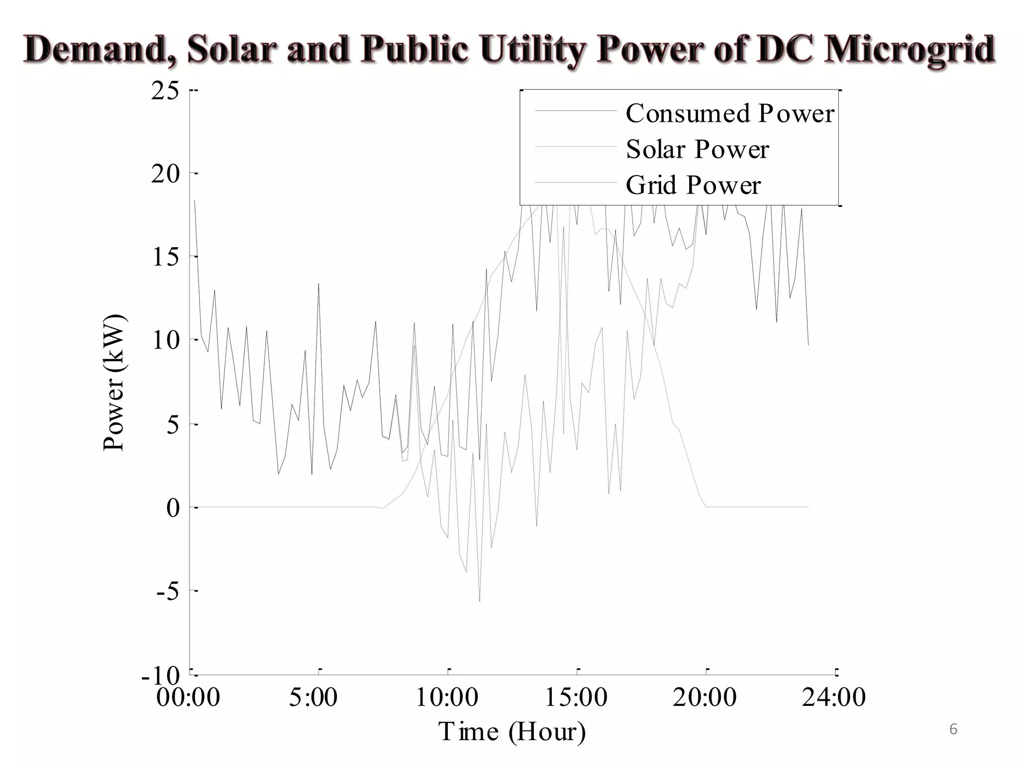
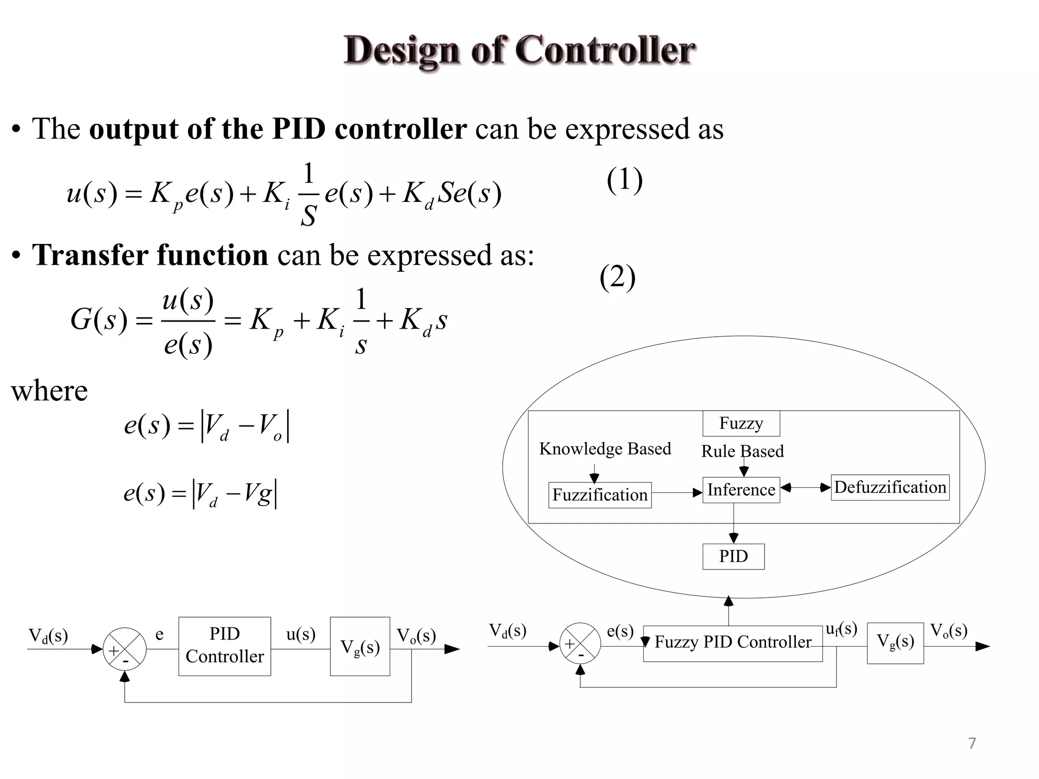
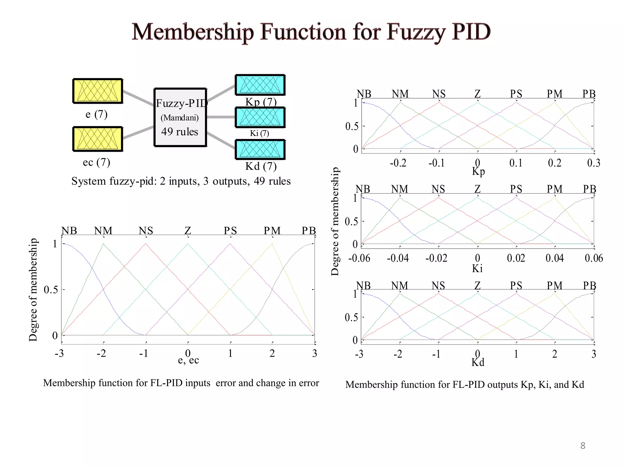

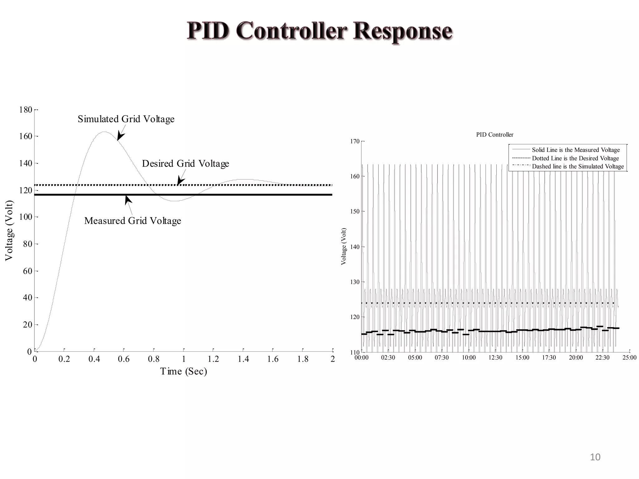
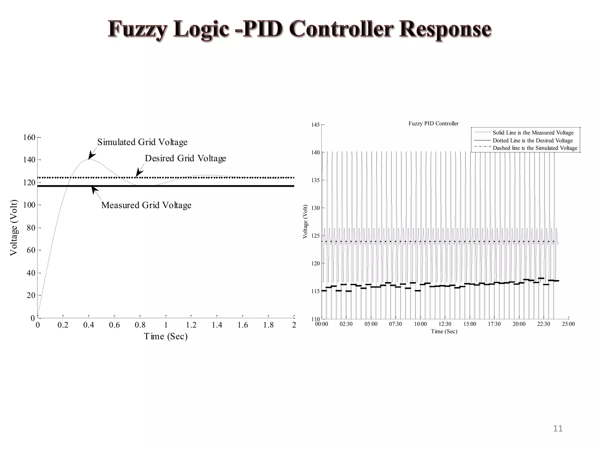
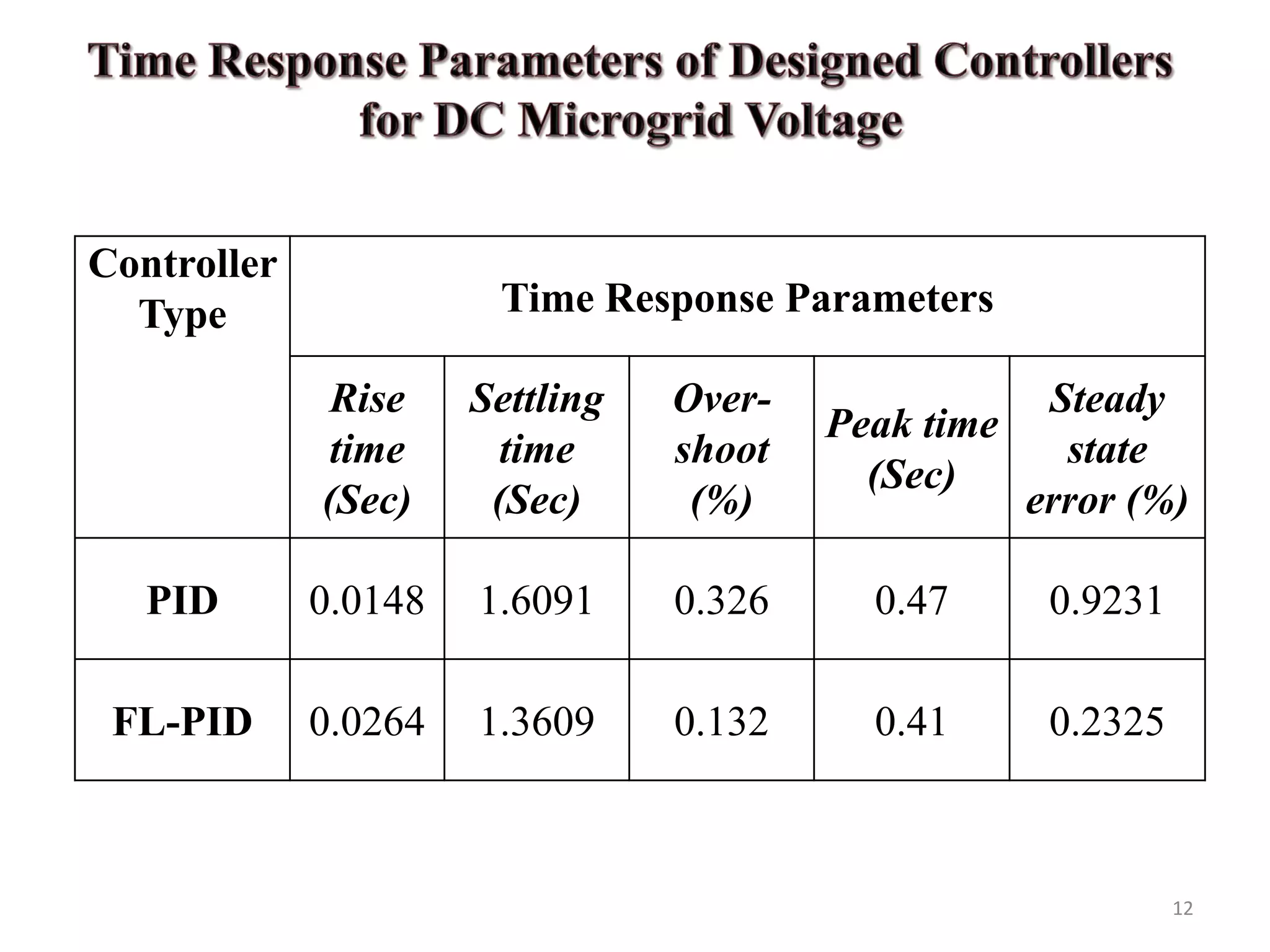
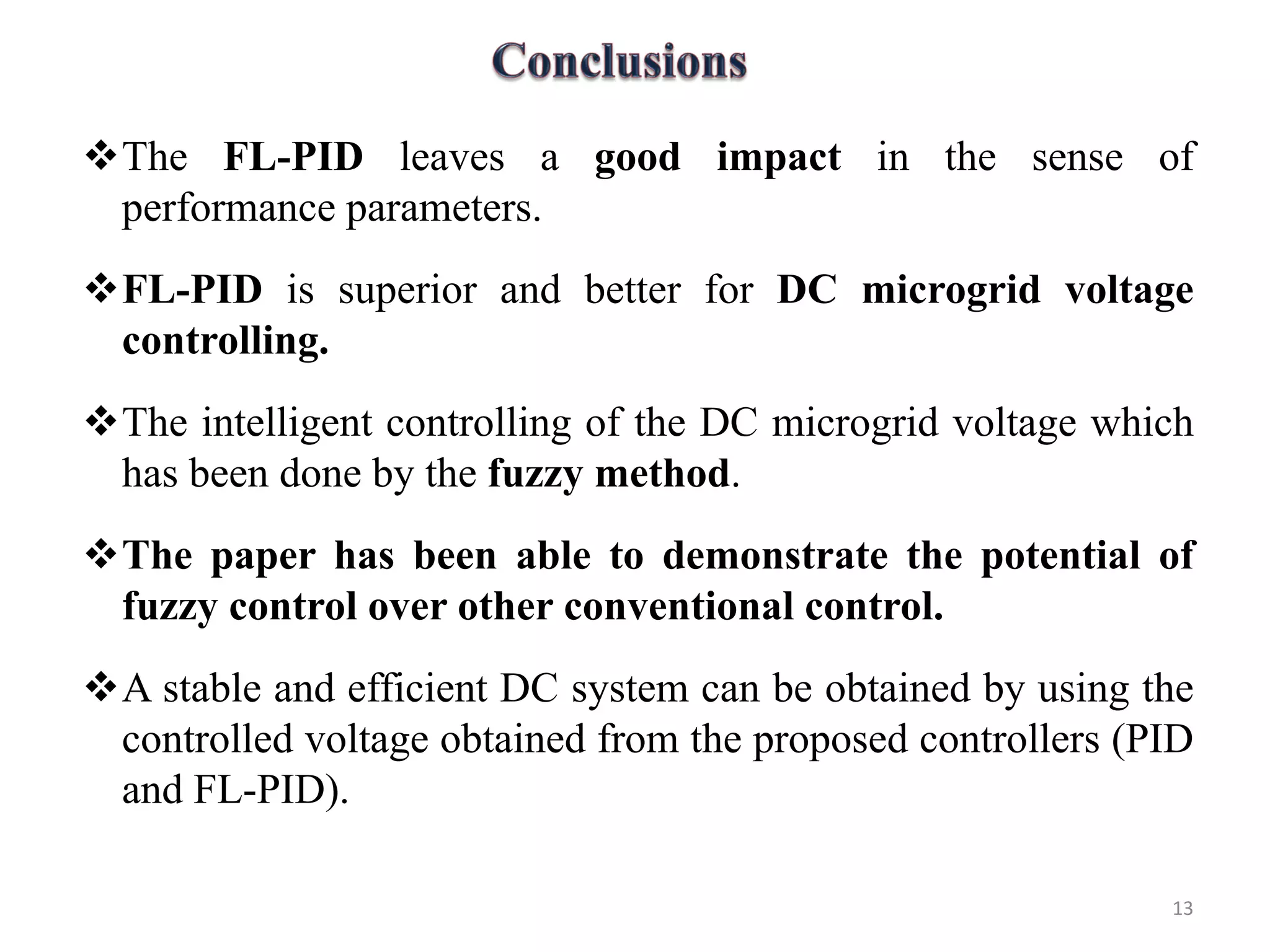


The document discusses the design and analysis of PID and fuzzy-PID controllers aimed at voltage control in DC microgrids, emphasizing stability challenges and voltage fluctuation due to demand variations. It highlights the effectiveness of the fuzzy-PID controller in achieving superior performance parameters compared to the standard PID controller. The findings suggest that intelligent fuzzy control can enhance voltage stability and control in DC microgrid systems.