The document presents the design and implementation of variable and constant loads for induction motors (IM) utilizing both PI and fuzzy-PI controllers to improve performance under various operating conditions. It includes simulation models for IM under no load, constant load, and variable load scenarios, demonstrating that the fuzzy-PI controller provides superior results compared to the conventional PI controller. The study concludes that using artificial intelligence techniques enhances control for nonlinear systems, offering better operational efficiency.
![International Journal of Power Electronics and Drive System (IJPEDS)
Vol. 11, No. 2, June 2020, pp. 762~773
ISSN: 2088-8694, DOI: 10.11591/ijpeds.v11.i2.pp762-773 762
Journal homepage: http://ijpeds.iaescore.com
Design and implementation of variable and constant load for
induction motor
Salam Waley Shneen1
, Hashmia Sh.Dakheel2
, Zainab B.Abdulla3
1 Energy and Renewable Energies Technology Center, University of Technology, Iraq
2,3 Department of Electromechanical, University of Technology, Iraq
Article Info ABSTRACT
Article history:
Received Jul 19, 2019
Revised Dec 2, 2019
Accepted Feb 4, 2020
To design and implementation of variable and constant with no load for
induction motor (IM) that is the goal in this work. This paper was including
three parts, first the simulation model with no load for IM, Second the
simulation model with constant load for IM, Third the simulation model with
variable load for IM. In addition, this work includes comparative between
two different controllers (PI and fuzzy logic control (FLC). The simulation
results clearly the implementation of variable and constant with no load for
IM. The simulation response of the system achieves better results when
choosing to use type fuzzy-PI controller technique comparison with
conventional PI controller and improve the performance of the system at
different operation conditions.
Keywords:
FLC
IM
PI
Transfer function
This is an open access article under the CC BY-SA license.
Corresponding Author:
Salam Waley Shneen,
Energy and Renewable Energies Technology Center,
University of Technology,
52 Industry street, Baghdad, Iraq.
Email: salam_waley73@yahoo.com
1. INTRODUCTION
The 3-phase IM is important of electrical machines that widely used in different industrial applications [1].
They perform their characteristic for decades and adapt themselves at different operate conditions [2], such as oil
refineries, electric power stations, and factories because their simple in design, high efficiency, good self-starting, good
power factor, low manufacturing costs relatively, and small value of inertia [3]. The disadvantages of IM have
represented in non-linear multivariable in addition to complex of mathematical model, so IM inherently unable to operate
at different range of speed, therefore to solve these problems is used multi types of controllers such as PI controllers.
Very comprehensive remarks era that gives a very efficient method to several manipulate problems inside the real world.
These controllers are simplicity, reliability. Robust of the systems and tuned properly therefore they becomes important
in industrial applications.
However, PI controller can't offer the good control overall performance in running condition [4]. The authors of
[5-7] are present hybrid control system by using FLC and conventional controllers by using mathematical of IM and these
studies deals with the structure of model to obtain high-performance tracking of IM. In [8] proposes speed control of IM
by using conventional techniques (PI and PID) controllers with vector control technique at full load condition and discuss
simulation results with these controllers and without any controller. The study [9] proposes system to control on speed of
IM by using feedback close loop system with fuzzy-PID controller. This system has other advantages that combination
between 3-phase step-up transformer and 3-phase drive to able control any 3-phase machine on a 1-phase supply, also
study [10] refers speed control of IM by using MATLAB Toolbox and Simulink model to developed this model by using
FLC which available constant speed at varies loads conditions. Many studies had proposed different approach to resolve
the downside of (PI controller). The usage of artificial intelligence techniques (AIT) so one of these techniques are very
important for controlling non-linear system without independent on behaviors of internal system such as (FLC) that](https://image.slidesharecdn.com/24203175feb2020finalcopyedilham-210701060454/85/Design-and-implementation-of-variable-and-constant-load-for-induction-motor-1-320.jpg)
![International Journal of Power Electronics and Drive System (IJPEDS)
Vol. 11, No. 2, June 2020, pp. 762~773
ISSN: 2088-8694, DOI: 10.11591/ijpeds.v11.i2.pp762-773 762
Journal homepage: http://ijpeds.iaescore.com
Design and implementation of variable and constant load for
induction motor
Salam Waley Shneen1
, Hashmia Sh.Dakheel2
, Zainab B.Abdulla3
1 Energy and Renewable Energies Technology Center, University of Technology, Iraq
2,3 Department of Electromechanical, University of Technology, Iraq
Article Info ABSTRACT
Article history:
Received Jul 19, 2019
Revised Dec 2, 2019
Accepted Feb 4, 2020
To design and implementation of variable and constant with no load for
induction motor (IM) that is the goal in this work. This paper was including
three parts, first the simulation model with no load for IM, Second the
simulation model with constant load for IM, Third the simulation model with
variable load for IM. In addition, this work includes comparative between
two different controllers (PI and fuzzy logic control (FLC). The simulation
results clearly the implementation of variable and constant with no load for
IM. The simulation response of the system achieves better results when
choosing to use type fuzzy-PI controller technique comparison with
conventional PI controller and improve the performance of the system at
different operation conditions.
Keywords:
FLC
IM
PI
Transfer function
This is an open access article under the CC BY-SA license.
Corresponding Author:
Salam Waley Shneen,
Energy and Renewable Energies Technology Center,
University of Technology,
52 Industry street, Baghdad, Iraq.
Email: salam_waley73@yahoo.com
1. INTRODUCTION
The 3-phase IM is important of electrical machines that widely used in different industrial applications [1].
They perform their characteristic for decades and adapt themselves at different operate conditions [2], such as oil
refineries, electric power stations, and factories because their simple in design, high efficiency, good self-starting, good
power factor, low manufacturing costs relatively, and small value of inertia [3]. The disadvantages of IM have
represented in non-linear multivariable in addition to complex of mathematical model, so IM inherently unable to operate
at different range of speed, therefore to solve these problems is used multi types of controllers such as PI controllers.
Very comprehensive remarks era that gives a very efficient method to several manipulate problems inside the real world.
These controllers are simplicity, reliability. Robust of the systems and tuned properly therefore they becomes important
in industrial applications.
However, PI controller can't offer the good control overall performance in running condition [4]. The authors of
[5-7] are present hybrid control system by using FLC and conventional controllers by using mathematical of IM and these
studies deals with the structure of model to obtain high-performance tracking of IM. In [8] proposes speed control of IM
by using conventional techniques (PI and PID) controllers with vector control technique at full load condition and discuss
simulation results with these controllers and without any controller. The study [9] proposes system to control on speed of
IM by using feedback close loop system with fuzzy-PID controller. This system has other advantages that combination
between 3-phase step-up transformer and 3-phase drive to able control any 3-phase machine on a 1-phase supply, also
study [10] refers speed control of IM by using MATLAB Toolbox and Simulink model to developed this model by using
FLC which available constant speed at varies loads conditions. Many studies had proposed different approach to resolve
the downside of (PI controller). The usage of artificial intelligence techniques (AIT) so one of these techniques are very
important for controlling non-linear system without independent on behaviors of internal system such as (FLC) that](https://image.slidesharecdn.com/24203175feb2020finalcopyedilham-210701060454/75/Design-and-implementation-of-variable-and-constant-load-for-induction-motor-1-2048.jpg)
![Int J Pow Elec & Dri Syst ISSN: 2088-8694
Design and implementation of variable and constant load for induction motor (Salam Waley Shneen)
763
permits designers to address efficaciously difficult closed loop system in order to reduce time as well as costs, supports
non-linear system which can be using in motor control fields [11]. PI controller can be tuned the gain by (AIT), (FLC)
and online tuned with changing conditions of system [12], the controller gains are the best advantage of these controllers
because which allow using the human experience for the generation of the tuning law [13]. This study provides fuzzy-PI
controller that FLC adjust parameters of PI and comparative with conventional PI controller at different operation
conditions include (no load, constant and variable loads) of IM in order to improve operation of this motor and obtain
high performance at real time.
2. MATHEMATICAL MODEL OF IM:-
The equivalent circuit of IM for (q and d winding circuit) which can be used to analysis the model of IM shows
in Figure 1, while power circuit of the 3-phase IM shows in Figure 2 [14,15].
(a) (b)
Figure 1. Equivalent circuit of IM
Figure 2. Power circuit of 3-phase IM
Dynamic model of IM can represent by writing deferential equation for electrical and mechanical quantities (voltage and
torque) and can shown in mathematical model of IM include the equations below [3].
A-Electrical system equations
𝑣 𝑅 𝑖 𝑤 𝑀 𝜆 (1)
𝑣 𝑅 𝑖 𝑤 𝑤 𝑀 𝜆 (2)
Here 𝜆 , 𝑖 , 𝑀
0 1
1 0
B- Flux linkage-current relations
For d-axis:
𝜆 𝐿 𝑖 𝐿 𝑖 (3)
𝜆 𝐿 𝑖 𝐿 𝑖 (4)
For q axis:
𝜆 𝐿 𝑖 𝐿 𝑖 (5)
𝜆 𝐿 𝑖 𝐿 𝑖 (6)
Where 𝐿 𝐿 𝐿 , 𝐿 𝐿 𝐿](https://image.slidesharecdn.com/24203175feb2020finalcopyedilham-210701060454/85/Design-and-implementation-of-variable-and-constant-load-for-induction-motor-2-320.jpg)
![ ISSN: 2088-8694
Int J Pow Elec & Dri Syst, Vol. 11, No. 2, June 2020 :762 – 773
764
C- Mechanical system equations:-
𝑇 2𝐻 𝐵 𝑤 𝑇 (7)
Where 𝑇 , 𝜆 ∗ 𝑖 𝑀 𝜆 ∗ 𝑖 (8)
𝑤 𝑤 (9)
3. Induction motor and controller
This paper proposes operation of IM at different conditions such as (no load, constant and variable loads)
without controller and by using each of PI and fuzzy-PI controller to develop performance of IM at different operation
conditions, the following steps in this paper present in the flow chart which shows in Figure 3.
Figure 3. Flow chart for performance of model
3.1. Simulation of induction motor
The 3-phase voltages and frequency are inputs of a squirrel cage IM, while the 3- phase currents, torque and
rotor speed are outputs of IM model [14]. Simulink model of IM shows in Figure 4.
Figure 4. Simulink model of IM](https://image.slidesharecdn.com/24203175feb2020finalcopyedilham-210701060454/85/Design-and-implementation-of-variable-and-constant-load-for-induction-motor-3-320.jpg)
![Int J Pow Elec & Dri Syst ISSN: 2088-8694
Design and implementation of variable and constant load for induction motor (Salam Waley Shneen)
765
The parameters of the IM propose in this paper as shown in Table 1.
Table 1. parameters of IM
parameters values
P (AV) 3*746
V ( line-line) 220 (r.m.s)
f (Hz) 60
Rs ( Ω) 0.435
Ls (H) 2*2e-3
Rr ( Ω) 0.816
Lr(H) 2e-3
Lm (H) 69.31e-3
J (kg.m^2) 0.089
Fc 0
Pole pair 2
Where:
P= power, V = Voltage, f = frequency, Rs = stator resistance, Ls = stator inductance, Rr = rotor resistance, Lr = rotor
inductance, Lm = mutual inductance, J= inertia, Fc = friction factor.
3.2.PI controller
PI controller can propose high performance only when the controller system operates at operating point, so the
PI controller does not frequently properly tune at operating condition changes and variations of parameters, in order to
develop automatic tuning of PI controller parameters [13]. PI controller drives plant to control weighted summation of
error and integration of values. The conventional or linear PI controller has described in 10.
𝑌 𝑡 𝑒 𝑡 𝐾 𝐾 𝑒 𝑡 𝑑𝑡 (10)
Where Kp is the proportional gain and Ki is integral gain of controller while error signal e(t) is the difference between the
reference r(t) and the process output c(t) [8].
𝑒 𝑡 𝑟 𝑡 𝑐 𝑡 (11)
Table 2. indicates effect of parameters for PI on controller system, whereas Figure 5 refers to block diagram of
this controller.
Table 2. effect of parameters of PI
parameters trise t over shoot ttuning error
kp Dec. Incr. Small change Dec.
ki Dec. Incr. Incr. eliminate
Where:
Dec.= decrese , Incr= increase,
Figure 6 shows PI -controller structure (kp, ki) are input of PI -controller and (u) is output [16, 17].
Figure 5. Simulink and block diagram of PI controller Figure 6. The structure of PI controller
3.3.Fuzzy-PI controller
The (FLC) is one of best applications where the fuzzy theory can apply successfully, so it can solve
problems in nonlinear control system but the system model is complex to build therefore knowledge of the
process is important to obtain the fuzzy rules. (FLC) consists of 3 steps: 1) fuzzification 2) evaluation of
control rules 3) defuzzification [18]. (FLC) have the advantages more than the classical control. They are](https://image.slidesharecdn.com/24203175feb2020finalcopyedilham-210701060454/85/Design-and-implementation-of-variable-and-constant-load-for-induction-motor-4-320.jpg)
![ ISSN: 2088-8694
Int J Pow Elec & Dri Syst, Vol. 11, No. 2, June 2020 :762 – 773
766
including wide range of operating cases. Cheaper to improve and easier in neural language expressions.
Mamdani is type of (FLC) can use in two systems. The first is multiple inputs multiple outputs while the
other is multiple input and signal output system. The interest of (FLC) is adopted operators experiment or
knowledge of the system in a heuristic way and in design process, the thresholds of fuzzy lingual variables
are often selection randomly so an incorrect controller values reach to unstable mode, an opposite
consequence, breakdown and separation [19, 20]. Figure 7 refers to block diagram of (FLC) [21].
Figure 7. Block diagram of (FLC)
The main goales of (fuzzy-PI) controller are to decrease control planner complication and develop
dynamic and static performances of the system. Essentially for systems designing are complex. The
parameters are difficult to obtain in this state. The (PI) controller is designed to set parameters Kp and Ki
orderly to meet suitable required characteristics include rise time, maximum value of overshoot, steady state
error and settling time. Therefore, (FLC) control signal according to the integral and proportional actions of
the PI-controller [13]. (FLC) has (2) inputs are represented error e(k) and change of error Δe(k).
e(k) = r(k)−y(k), Δe(k) =e(k) − e(k − 1)
where (r ) indicated to applied set point input and (y) denote to plant output, (k) indicate present
state whereas (k−1) is previous case of this system, while output of (FLC) is gradual change in value of Δe(k)
[22], Figure 8 inducates to block diagram of ( fuzzy-PI ) controller [23].
Figure 8. Block diagram of (fuzzy –PI) controller
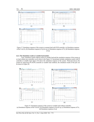
4. SIMULINK MODEL AND SIMULATION RESULTS
4.1.Simulink model
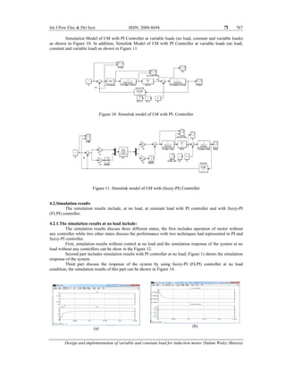
Figure 9 Shows simulation model of IM without controller at variable conditions of load (no load,
constant and variable load) as follows.
Figure 9. Simulink Model of I.M without Controller](https://image.slidesharecdn.com/24203175feb2020finalcopyedilham-210701060454/85/Design-and-implementation-of-variable-and-constant-load-for-induction-motor-5-320.jpg)


![ ISSN: 2088-8694
Int J Pow Elec & Dri Syst, Vol. 11, No. 2, June 2020 :762 – 773
772
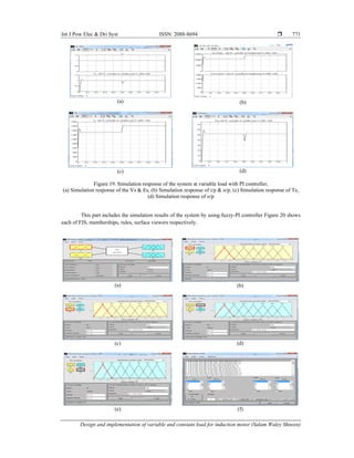
(g)
Figure 20. Simulation response of the system at variable load with FLPI controller, (a) FIS of FLPI, (b)
membership function of (error), (c) Membership function of I/P (change of error), (d) Membership function
of O/P (Kp), (e) Membership function of O/P (Ki), (f) Rules of FIPI, (g) Surface viewer of FIPI
The difference between the different simulations can observe by responding to each case and
comparing it with the response of any other case that simulates the operation of the engine with different
states. When looking at all cases in terms of response: close symmetry appears, and when looking at
the response clearly. A slight difference can be observed. It is almost an override of 2 rad / s, and then it can
be said that a better response has obtained. A slight difference can observe by taking the time to reach the
stable state and these are the system specifications to demonstrate the differences and to determine better
performance. It includes Steady state error (ess), Peak Overshoot (Mp) and Settling Time (tss) that shows the
better state by using fuzzy logic controller compared to conventional PID.
5. CONCLUSION
The main object of this paper is to implement a controller based on adaptive fuzzy-PI and
conventional PI by using MathLab Simulink environment in order to improve the performance of three-phase
induction motor under different operation conditions represent in (no-load, constant and variable loads),
simulation results refer to successful techniques with high accuracy by using fuzzy-PI than conventional PI.
REFERENCES
[1] Mahdi Atig, Mustapha Bouheraoua, Arezki Fekik, "An Experimental Investigation of Heating in Induction Motor
under Open Phase Fault," International Journal of Electrical and Computer Engineering (IJECE), vol. 8, no. 3, pp.
1288-1296, June 2018.
[2] Aderibigbe, Israel Adekitan, Adeyinka Adewale, and Alashiri Olaitan, "Determining the operational status of a
Three Phase Induction Motor using a predictive data mining model," International Journal of Power Electronics
and Drive Systems, vol. 10, no. 1, pp. 93-103, 2019.
[3] Farah, Nabil, et al., "Self-tuning Fuzzy Logic Controller Based on Takagi-Sugeno Applied to Induction Motor
Drives," International Journal of Power Electronics and Drive Systems, vol. 9, no. 4, pp. 1967-1975, 2018.
[4] Abdullah, Afrah Thamer, and Amer Mejbel Ali, "Thermal analysis of a three-phase induction motor based on
motor-CAD, flux2D, and matlab," Indonesian Journal of Electrical Engineering and Computer Science, vol. 15,
no. 1, pp. 46-53, 2019.
[5] Denai, Mouloud Azzedine, and Sid Ahmed Attia, "Fuzzy and neural control of an induction motor," Applied
mathematics and computer science, vol. 12, no. 2, pp. 221-234, 2002.
[6] Ayushi, "Speed Control of Induction Motor using Fuzzy Logic Controller," International Journal of Advanced
Research in Electrical, Electronic and Instrumentation Engineering, vol.4, no.4, pp. 2581-2588, Apr, 2015.
[7] M. Zerikat, and S. Chekroun, “Design and Implementation of a Hybrid Fuzzy Controller for a High-Performance
Induction Motor," International Journal of Electrical, Computer Energetic, Electronic and Communication
Engineering, vol.1, no. 2, pp. 202-208, 2007.
[8] Madhavi L. Mhaisgawali, Mrs.S.P. Muley, "Speed Control of Induction Motor using PI and PID Controller," IOSR
Journal of Engineering (IOSRJEN), vol.3, no. 5, pp.25-30, May 2013.
[9] Mr. Bidwe Umesh. B., Mr. Shinde Sanjay. M., " Speed Control of Three Phase Induction Motor using Fuzzy- PID
Controlller," International Journal of Engineering Research and Technology (IJERT), vol. 2, no. 11, pp. 3794–
3799, Nov 2013.
[10] Kamini Devi, Shailendra Gautam, Deepak Nagaria, " Speed Control of 3-Phase Induction Motor Using Self-Tuning
Fuzzy PID Controller and Conventional PID Controller," International Journal of Information and Computation
Technology, vol. 4, no.12, pp.1185-1193, 2014.](https://image.slidesharecdn.com/24203175feb2020finalcopyedilham-210701060454/85/Design-and-implementation-of-variable-and-constant-load-for-induction-motor-11-320.jpg)
![Int J Pow Elec & Dri Syst ISSN: 2088-8694
Design and implementation of variable and constant load for induction motor (Salam Waley Shneen)
773
[11] Hesari, Sadegh, et al., "Investigating the Intelligent Methods of Loss Minimization in Induction Motors,"
TELKOMNIKA (Telecommunication, Computing, Electronics and Control), vol. 16, no.3, pp. 1034-1053, 2018.
[12] Salam Waley, Chengxiong Mao, "Artificial Optimal Fuzzy Control Strategy for Elevator Drive System by Using
Permanent Magnet Synchronous Motor", Indonesian Journal of Electrical Engineering and Computer Science, vol.
14, no. 3, pp. 470-480, Jun 2015,
[13] Ahmed m. Kassem, "Fuzzy-Logic Based Self-Tuning PI Controller for High-Performance Vector Controlled
Induction Motor Fed PV-Generator," WSEAS TRANSACTION on SYSTEMS, vol. 12, no. 1, Jan, 2013.
[14] Hanan Mikhael D. Habbi, Hussein Jalil Ajeel, Inaam Ibrahim Ali, "Speed Control of Induction Motor using PI and
V/F Scalar Vector Controllers," International Journal of Computer Applications, vol. 151, no. 7, pp. 36-43,
Oct 2016.
[15] Naveena G J, Murugesh Dodakundi, Anand Layadgundi, "Speed control of an induction motor using fuzzy logic
and pi controller and comparison of controllers based on speed," International Journal of Electrical and
Electronics Engineers, vol. 7, no. 1, 2015.
[16] Adnan Jabbar Attiya, Yang Wenyu1, Salam Waley Shneen, "Compared with PI, Fuzzy-PI and PSO-PI controllers
of robotic grinding force servo system," Indonesian Journal of Electrical Engineering and Computer Science, vol.
16, no. 1, pp. 65–74, Oct 2015.
[17] Adnan Jabbar Attiya, et al, "PSO_PI Controller of Robotic Grinding Force Servo System," Indonesian Journal of
Electrical Engineering and Computer Science vol. 15, no.3, pp. 515–525, Sep 2015.
[18] Bambang Purwahyudi, et al, "Self-Tuning Fuzzy-PI Controller in Volts/ Hz Induction Motor Control for
Electrically Driven Ship Propeller," Academic Research International, vol. 5, no. 5, pp. 86-94, Sep 2014.
[19] Salam Waley Shneen, "Advanced optimal for three phase rectifiers in power electronics system," Indonesian
Journal of Electrical Engineering and Computer Science, vol. 11, no. 3, pp.821-830, Sep 2018.
[20] Salam Waley, Chengxiong Mao, Nasseer K. Bachache, "Biogeography Based Optimization Tuned Fuzzy Logic
Controller to Adjust Speed of Electric Vehicle," Indonesian Journal of Electrical Engineering and Computer
Science, vol. 16, no. 3, pp. 509-519, Dec 2015.
[21] Adnan Jabbar Attiya, et al, "Fuzzy-PID controller of robotic grinding force servo system," Indonesian Journal of
Electrical Engineering and Computer Science, vol. 15, no. 1, pp. 87–99, Jul 2015.
[22] Yakala Satyanarayana, Dr.A. Srujana, "Speed Control of Induction Motor using Fuzzy PI Controller based on
Space Vector Pulse Width Modulation", International Journal of Computational Engineering Research, vol. 2,
no. 5, pp. 1203-1209, Sep 2012.
[23] Ismail Khalil Bousserhane, Abdeldjebar Hazzab, Mostefa Rahli, Benyounes Mazari, Mokhtar Kamli, "Optimal
fuzzy gains scheduling of PI controller for induction motor speed control," Faculty of Electrical Engineering and
Informatics, Technical University of Kosice, Solvak Republic, vol. 7, No.1, 2007](https://image.slidesharecdn.com/24203175feb2020finalcopyedilham-210701060454/85/Design-and-implementation-of-variable-and-constant-load-for-induction-motor-12-320.jpg)


![[000008]](https://cdn.slidesharecdn.com/ss_thumbnails/000008-211028000724-thumbnail.jpg?width=640&height=640&fit=bounds)