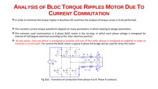
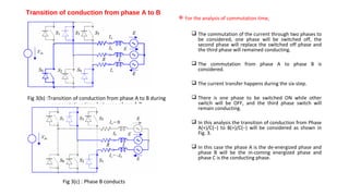
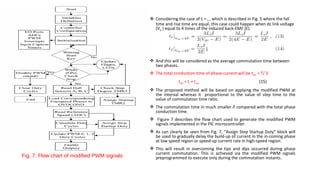
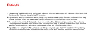
The document discusses torque ripple minimization in BLDC motors. It describes how torque ripples occur during current commutation between phases in BLDC motors due to mismatched current rise and fall times. A proposed PWM switching strategy uses modified PWM signals to speed up or slow down the energized phase current during commutation based on motor speed, minimizing torque ripples. Experimental results show that the modified PWM approach reduces current spikes and dips during commutation, resulting in lower torque ripple compared to conventional PWM control.
discusses about the reduction of commutation torque ripple in BLDC motor and various convention methods and the proposed method for 2 level inverter and 3 level inverter
Torque Ripple Minimization of a BLDC Motor Drive by Using Electronic Commutat...AI Publications
Brushless DC motors are having a major problem with harmonics in torque. The variations in speed and production of noise should be minimized by using proper topologies. BLDC motors have been gaining attention from different Industrial and domestic appliance manufacturers, because of their high efficiency, high power density and easy maintenance and low cost. This paper presents a three phase BLDC motor with low cost drive to be driven without DC link capacitor. The proposed technique uses an electronic commutation and operates the machine exclusive of the intermediate DC link capacitor. The designing of Brushless DC motor drive system along with control system for torque ripple minimization, speed controller and current controllers are presented using MATLAB / SIMULINK and results are evaluated.
Drives lec 15_16_Armature Voltage based Speed Control MethodsMohammad Umar Rehman
Part of Lecture series on EEE-413, Electrical Drives (DC Drives) delivered by me to students of VIII Semester B.E. (Electrical), Session 2018-19.
Z. H. College of Engg. & Technology, Aligarh Muslim University, Aligarh.
Missing materials will be uploaded shortly.
Please comment and feel free to ask anything related. Thanks!
This presentation was presented to Dr. Chongru Liu in North China Electric Power University,Beijing,China by Mr. Aazim Rasool. This presentation will help to understand the control of HVDC system. Animations are not working like ppt. so I apologize on this.
Performance of Six-Pulse Line-Commutated Converter in DC Motor Drive ApplicationZunAib Ali
This paper presents the speed control of DC motor using six pulse controlled rectifier. The
conventional Proportional Integral (PI) control is used for firing angle control. The armature current is fed
back and compared with reference current representing desired speed values. The proposed system is
simulated using SimPowerSystem and Control System Matlab toolbox. The time domain plot of reference
and actual armature current are shown in results section. The results are satisfactory with deleterious effect
on input current. The frequency plot of input current is provided to show the harmonic contents, generated
as a result of control operation.
LCL Filter for Grid Connected VSC Converter
Comprehensive analysis and modeling of the three-phase LCL filter for VSC converters, suitable for wind energy or photovoltaic applications.
Closed Loop Speed Control of a BLDC Motor Drive Using Adaptive Fuzzy Tuned PI...IJERA Editor
Brushless DC Motors are widely used for many industrial applications because of their high efficiency, high
torque and low volume. This paper proposed an improved Adaptive Fuzzy PI controller to control the speed of
BLDC motor. This paper provides an overview of different tuning methods of PID Controller applied to control
the speed of the transfer function model of the BLDC motor drive and then to the mathematical model of the
BLDC motor drive. It is difficult to tune the parameters and get satisfied control characteristics by using normal
conventional PI controller. The experimental results verify that Adaptive Fuzzy PI controller has better control
performance than the conventional PI controller. The modeling, control and simulation of the BLDC motor have
been done using the MATLAB/SIMULINK software. Also, the dynamic characteristics of the BLDC motor (i.e.
speed and torque) as well as currents and voltages of the inverter components are observed by using the
developed model.
Infinite bus bar is one which keeps constant voltage and frequency although the load varies. Thus it may behave like a voltage source with zero internal impedance and infinite rotational inertia.
In analyzing the problems in South Sulawesi transmission system, simulations of PSCAD / EMTDC [5-6] and PWS (Power World Simulator) [7] software were used to simulate changes in electrical current and voltage during a disturbance.
-Single phase to Ground,
-Line to Fault Line,
-Double Line to Ground
-Three phase Short Circuit
Speed Control of Induction Motor using Variable Frequency DriveSandeep Kaushal
Induction motor is constant speed motor at a particular frequency and consumes almost same power irrespective of load demand. Let's talk about two different load one is high load and other low load. AT low load motor is delivering the load with some current and thereby torque is maintained. If load goes high, to maintain the same speed and developed torqued, motor will draw extra current and will corresponds to more losses. If speed of motor is reduced corresponding too low load and is increased corresponding to high load, then substantial amount of power can be saved. And speed can be changed by changing the frequency of input supply.
Injection of the wind power into an electric grid affects the power quality. The performance of the wind turbine and thereby power quality are determined on the basis of measurements and the norms followed according to the guideline specified in International Electro-technical Commission standard, IEC-61400. The influence of the wind turbine in the grid system concerning the power quality measurements are-the active power, reactive power, variation of voltage, flicker, harmonics, and electrical behavior of switching operation and these are measured according to national/international guidelines. The paper study demonstrates the power quality problem due to installation of wind turbine with the grid. In this proposed scheme STATic COMpensator (STATCOM) is connected at a point of common coupling with a battery energy storage system (BESS) to mitigate the power quality issues. The battery energy storage is integrated to sustain the real power source under fluctuating wind power. The STATCOM control scheme for the grid connected wind energy generation system for power quality improvement is simulated using MATLAB/SIMULINK in power system block set. The effectiveness of the proposed scheme relives the main supply source from the reactive power demand of the load and the induction generator. The development of the grid co-ordination rule and the scheme for improvement in power quality norms as per IEC-standard on the grid has been presented.
IJERA (International journal of Engineering Research and Applications) is International online, ... peer reviewed journal. For more detail or submit your article, please visit www.ijera.com
This paper proposed a new sparce matrix converter with Z-source network to provide unity voltage transfer ratio. It is an ac-to-ac converter with diode-IGBT bidirectional switches. The limitations of existing matrix converter like higher current THD and less voltage transfer ratio issues are overcome by this proposed matrix converter by inserting a Z-source. Due to this Z-source current harmonics are totally removed. The simulation is performed for different frequencies. The simulation results are presented to verify the THD and voltage transfer ratio and compared with the existing virtual AC/DC/AC matrix converter. The experimental output voltage amplitude can be varied with the variable frequencies.
This directional over current relay employs the principle of actuation of the relay....It has a metallic disc free to rotate between the poles of two...
Research Inventy : International Journal of Engineering and Scienceinventy
Research Inventy : International Journal of Engineering and Science is published by the group of young academic and industrial researchers with 12 Issues per year. It is an online as well as print version open access journal that provides rapid publication (monthly) of articles in all areas of the subject such as: civil, mechanical, chemical, electronic and computer engineering as well as production and information technology. The Journal welcomes the submission of manuscripts that meet the general criteria of significance and scientific excellence. Papers will be published by rapid process within 20 days after acceptance and peer review process takes only 7 days. All articles published in Research Inventy will be peer-reviewed.
Development of Switch Mode Dc Converter Using MATLAB/ dSPACEIDES Editor
In this paper with the help of Matlab/Simulink and
dSPACE, the Switch-Mode DC Converter is built in real-time
to control the output voltage of the controller using PWM
algorithm. First, the Simulink model of Switch-Mode DC
Converter (i.e. Single-Pole and Two-Pole Converter Model)
is built and, after verifying the results, it is implemented in
real-time. Next, a DC motor is connected to the output
terminals (i.e. Phase A1 and Phase B1) of the Power Electronics
Board such that a variable voltage is applied to the terminals
of DC motor. Now, by changing the magnitude of the applied
voltage, the speed of the motor is varied. This is also referred
to as an open-loop voltage control of DC motor. The purpose
of the real-time implementation is obtaining variable voltage
at the output of the power converter, while controlling its
amplitude with a dSPACE DS1104-based user interface.
An Active Input Current Waveshaping with Zero Switching Losses for Three-Phas...IDES Editor
In this paper a zero voltage switched active network
(Fig. 1) which can be used in conjunction with single-phase or
three-phase ac to dc diode rectifiers is presented. It is shown
that application of the proposed switching network in threephase
ac to dc boost converter yields zero switching losses
while maintaining a unity input power factor. Active network
capacitor, Cs, diodes D7, and D8, maintain a zero voltage during
turn-off of Q1, and Q2, Capacitor, Cs, discharges through
the boost inductors of the circuit thus limiting the rate of rise
of current during turn-on. Moreover, the advantage of the
proposed active network is that it can maintain a zero voltage
switching over the entire range of the duty cycle of the operation.
Consequently, boost stage can be used directly to control
the dc bus voltage by varying the duty cycle at Constant switching
frequency. The resulting advantages include higher
switching frequencies, and better efficiency. Finally the operation
of the active switching network is verified experimentally
on a prototype three-phase ac to dc converter.
International Journal of Engineering Research and Development (IJERD)IJERD Editor
journal publishing, how to publish research paper, Call For research paper, international journal, publishing a paper, IJERD, journal of science and technology, how to get a research paper published, publishing a paper, publishing of journal, publishing of research paper, reserach and review articles, IJERD Journal, How to publish your research paper, publish research paper, open access engineering journal, Engineering journal, Mathemetics journal, Physics journal, Chemistry journal, Computer Engineering, Computer Science journal, how to submit your paper, peer reviw journal, indexed journal, reserach and review articles, engineering journal, www.ijerd.com, research journals,
yahoo journals, bing journals, International Journal of Engineering Research and Development, google journals, hard copy of journal
GDG Cloud Southlake #33: Boule & Rebala: Effective AppSec in SDLC using Deplo...James Anderson
Effective Application Security in Software Delivery lifecycle using Deployment Firewall and DBOM
The modern software delivery process (or the CI/CD process) includes many tools, distributed teams, open-source code, and cloud platforms. Constant focus on speed to release software to market, along with the traditional slow and manual security checks has caused gaps in continuous security as an important piece in the software supply chain. Today organizations feel more susceptible to external and internal cyber threats due to the vast attack surface in their applications supply chain and the lack of end-to-end governance and risk management.
The software team must secure its software delivery process to avoid vulnerability and security breaches. This needs to be achieved with existing tool chains and without extensive rework of the delivery processes. This talk will present strategies and techniques for providing visibility into the true risk of the existing vulnerabilities, preventing the introduction of security issues in the software, resolving vulnerabilities in production environments quickly, and capturing the deployment bill of materials (DBOM).
Speakers:
Bob Boule
Robert Boule is a technology enthusiast with PASSION for technology and making things work along with a knack for helping others understand how things work. He comes with around 20 years of solution engineering experience in application security, software continuous delivery, and SaaS platforms. He is known for his dynamic presentations in CI/CD and application security integrated in software delivery lifecycle.
Gopinath Rebala
Gopinath Rebala is the CTO of OpsMx, where he has overall responsibility for the machine learning and data processing architectures for Secure Software Delivery. Gopi also has a strong connection with our customers, leading design and architecture for strategic implementations. Gopi is a frequent speaker and well-known leader in continuous delivery and integrating security into software delivery.
20 Comprehensive Checklist of Designing and Developing a WebsitePixlogix Infotech
Dive into the world of Website Designing and Developing with Pixlogix! Looking to create a stunning online presence? Look no further! Our comprehensive checklist covers everything you need to know to craft a website that stands out. From user-friendly design to seamless functionality, we've got you covered. Don't miss out on this invaluable resource! Check out our checklist now at Pixlogix and start your journey towards a captivating online presence today.
Communications Mining Series - Zero to Hero - Session 1DianaGray10
This session provides introduction to UiPath Communication Mining, importance and platform overview. You will acquire a good understand of the phases in Communication Mining as we go over the platform with you. Topics covered:
• Communication Mining Overview
• Why is it important?
• How can it help today’s business and the benefits
• Phases in Communication Mining
• Demo on Platform overview
• Q/A
How to Get CNIC Information System with Paksim Ga.pptxdanishmna97
Pakdata Cf is a groundbreaking system designed to streamline and facilitate access to CNIC information. This innovative platform leverages advanced technology to provide users with efficient and secure access to their CNIC details.
In the rapidly evolving landscape of technologies, XML continues to play a vital role in structuring, storing, and transporting data across diverse systems. The recent advancements in artificial intelligence (AI) present new methodologies for enhancing XML development workflows, introducing efficiency, automation, and intelligent capabilities. This presentation will outline the scope and perspective of utilizing AI in XML development. The potential benefits and the possible pitfalls will be highlighted, providing a balanced view of the subject.
We will explore the capabilities of AI in understanding XML markup languages and autonomously creating structured XML content. Additionally, we will examine the capacity of AI to enrich plain text with appropriate XML markup. Practical examples and methodological guidelines will be provided to elucidate how AI can be effectively prompted to interpret and generate accurate XML markup.
Further emphasis will be placed on the role of AI in developing XSLT, or schemas such as XSD and Schematron. We will address the techniques and strategies adopted to create prompts for generating code, explaining code, or refactoring the code, and the results achieved.
The discussion will extend to how AI can be used to transform XML content. In particular, the focus will be on the use of AI XPath extension functions in XSLT, Schematron, Schematron Quick Fixes, or for XML content refactoring.
The presentation aims to deliver a comprehensive overview of AI usage in XML development, providing attendees with the necessary knowledge to make informed decisions. Whether you’re at the early stages of adopting AI or considering integrating it in advanced XML development, this presentation will cover all levels of expertise.
By highlighting the potential advantages and challenges of integrating AI with XML development tools and languages, the presentation seeks to inspire thoughtful conversation around the future of XML development. We’ll not only delve into the technical aspects of AI-powered XML development but also discuss practical implications and possible future directions.
GraphSummit Singapore | The Future of Agility: Supercharging Digital Transfor...Neo4j
Leonard Jayamohan, Partner & Generative AI Lead, Deloitte
This keynote will reveal how Deloitte leverages Neo4j’s graph power for groundbreaking digital twin solutions, achieving a staggering 100x performance boost. Discover the essential role knowledge graphs play in successful generative AI implementations. Plus, get an exclusive look at an innovative Neo4j + Generative AI solution Deloitte is developing in-house.
Generative AI Deep Dive: Advancing from Proof of Concept to ProductionAggregage
Join Maher Hanafi, VP of Engineering at Betterworks, in this new session where he'll share a practical framework to transform Gen AI prototypes into impactful products! He'll delve into the complexities of data collection and management, model selection and optimization, and ensuring security, scalability, and responsible use.
Dr. Sean Tan, Head of Data Science, Changi Airport Group
Discover how Changi Airport Group (CAG) leverages graph technologies and generative AI to revolutionize their search capabilities. This session delves into the unique search needs of CAG’s diverse passengers and customers, showcasing how graph data structures enhance the accuracy and relevance of AI-generated search results, mitigating the risk of “hallucinations” and improving the overall customer journey.
Sudheer Mechineni, Head of Application Frameworks, Standard Chartered Bank
Discover how Standard Chartered Bank harnessed the power of Neo4j to transform complex data access challenges into a dynamic, scalable graph database solution. This keynote will cover their journey from initial adoption to deploying a fully automated, enterprise-grade causal cluster, highlighting key strategies for modelling organisational changes and ensuring robust disaster recovery. Learn how these innovations have not only enhanced Standard Chartered Bank’s data infrastructure but also positioned them as pioneers in the banking sector’s adoption of graph technology.
GraphSummit Singapore | The Art of the Possible with Graph - Q2 2024Neo4j
Neha Bajwa, Vice President of Product Marketing, Neo4j
Join us as we explore breakthrough innovations enabled by interconnected data and AI. Discover firsthand how organizations use relationships in data to uncover contextual insights and solve our most pressing challenges – from optimizing supply chains, detecting fraud, and improving customer experiences to accelerating drug discoveries.
Observability Concepts EVERY Developer Should Know -- DeveloperWeek Europe.pdfPaige Cruz
Monitoring and observability aren’t traditionally found in software curriculums and many of us cobble this knowledge together from whatever vendor or ecosystem we were first introduced to and whatever is a part of your current company’s observability stack.
While the dev and ops silo continues to crumble….many organizations still relegate monitoring & observability as the purview of ops, infra and SRE teams. This is a mistake - achieving a highly observable system requires collaboration up and down the stack.
I, a former op, would like to extend an invitation to all application developers to join the observability party will share these foundational concepts to build on:
GridMate - End to end testing is a critical piece to ensure quality and avoid...ThomasParaiso2
End to end testing is a critical piece to ensure quality and avoid regressions. In this session, we share our journey building an E2E testing pipeline for GridMate components (LWC and Aura) using Cypress, JSForce, FakerJS…
Threats to mobile devices are more prevalent and increasing in scope and complexity. Users of mobile devices desire to take full advantage of the features
available on those devices, but many of the features provide convenience and capability but sacrifice security. This best practices guide outlines steps the users can take to better protect personal devices and information.
LF Energy Webinar: Electrical Grid Modelling and Simulation Through PowSyBl -...DanBrown980551
Do you want to learn how to model and simulate an electrical network from scratch in under an hour?
Then welcome to this PowSyBl workshop, hosted by Rte, the French Transmission System Operator (TSO)!
During the webinar, you will discover the PowSyBl ecosystem as well as handle and study an electrical network through an interactive Python notebook.
PowSyBl is an open source project hosted by LF Energy, which offers a comprehensive set of features for electrical grid modelling and simulation. Among other advanced features, PowSyBl provides:
- A fully editable and extendable library for grid component modelling;
- Visualization tools to display your network;
- Grid simulation tools, such as power flows, security analyses (with or without remedial actions) and sensitivity analyses;
The framework is mostly written in Java, with a Python binding so that Python developers can access PowSyBl functionalities as well.
What you will learn during the webinar:
- For beginners: discover PowSyBl's functionalities through a quick general presentation and the notebook, without needing any expert coding skills;
- For advanced developers: master the skills to efficiently apply PowSyBl functionalities to your real-world scenarios.
LF Energy Webinar: Electrical Grid Modelling and Simulation Through PowSyBl -...
Technical seminar
1. PWM SWITCHING STRATEGY FOR TORQUE
RIPPLE MINIMIZATION IN BLDC MOTOR
SUBMITTED BY
GAURAV
1SI09EE016
2. CONVENTIONAL DC MOTORS WITH BRUSHES.
• The field winding is on the stator and armature winding is on the rotor.
• The motor is relatively more expensive and needs maintenance due to the brushes and accumulation of the
brush debris, dust, and commutator surface wear.
• Moreover in certain hazardous locations, the application of DC brushed motors is limited due to the arcing.
SOLUTION
• This could be solved by replacing the mechanical switching components i.e. commutator and brushes by
power electronic switches.
3. • Brushless DC (BLDC) motor has a permanent magnet rotor and a wound field stator, which is
connected to a power electronic switching circuit.
• The BLDC control drive system is based on the feedback of rotor position, which is obtained at
fixed points typically every 60 electrical degrees for six-step commutations of the phase currents.
• FEATURES OF BLDC
• High efficiency
• Low maintenance,
• Longer life span,
• Low noise,
• Control simplicity
• And compact construction.
4. Why Torque Minimization???
Based on the shape of the back-EMF, the brushless motors can be classified to have either :
Trapezoidal
Or sinusoidal back-EMF
In a BLDC motor, the permanent magnets produce an air gap flux density distribution that is of
trapezoidal shape, hence, resulting in trapezoidal back- EMF waveforms.
The torque pulsations in PM BLDC motors are generally resulted from the deviation from ideal
conditions.
It can be either related to the design factors of the motor or to the power inverter current
excitation resulting in non-ideal current waveforms.
The undesired torque pulsation in PM BLDC motor drives may lead to speed oscillations,
resonances in mechanical portions of the drive causing acoustic noise and visible vibration
patterns in high precision machines
Therefore, the torque ripple minimization or elimination is a considerable issue in BLDC motor drives.
5. TORQUE PULSATION MINIMIZATION
The torque pulsations could typically be minimized by two techniques :
By the improved motor designs and
By improved control scheme.
1. By Improved motor design techniques for pulsating torque minimization
skewing,
fractional-slot winding,
short-pitch winding,
increased number of phases,
air gap windings,
adjusting stator slot opening and wedges,
rotor magnetic design through magnet pole arc, width and positions.
1. By Improved motor control schemes
adaptive control technique,
preprogrammed current waveform control,
selective harmonics injection techniques,
estimators and observers,
speed loop disturbance rejection,
high speed current regulators,
commutation torque minimizations
and automated self-commissioning schemes.
6. Fig 1. Brushless DC motor’s equivalent circuit Fig 2. BLDC drive system components
7. MATHEMATICAL MODEL OF BLDC MOTOR DRIVE
SYSTEM
BLDC motor produces a trapezoidal back-EMF, and therefore the excited current waveform is preferably rectangular-shaped.
The phase resistances of the stator windings are assumed to be equal.
The self and mutual inductances are constant irrespectively of rotor position due to surface mounted permanent magnet rotor
topology.
The rotor-induced currents are neglected and the damper windings are also not present.
The three phase voltage equation can be expressed as :
================ (1)
where
Rs : phase resistance, van, vbn, vcn : phase voltages,
Ls : self-inductance, ia, ib, ic : phase currents,
M :mutual inductance, ea, eb, ec : phase back-EMFs.
8. Due to the interaction of the currents in stator windings and the magnetic field from rotor magnets, the electromagnetic
torque of BLDC motor is produced as follows :
============= (2)
ωm is the mechanical speed of the rotor
=============(3)
where
TL : load torque,
B : damping constant,
J : moment of inertia of rotor shaft and load .
BLDC drive system typically consists of
BLDC motor,
power electronics converter,
hall-effect sensors
and controller
9. For six-step motor control, at each step the instantaneous output power will be will be deliver from two phases connected
in series, and is given by
Po= ωmTe = 2EI (4)
where I is the current amplitude and E is the induced back-EMF.
From equations (2) and (4), the output torque can also be expressed as
Te = 2kФI = 2ktI (5)
where kt is the motor torque constant.
10. ANALYSIS OF BLDC TORQUE RIPPLES MOTOR DUE TO
CURRENT COMMUTATION
In order to minimize the torque ripples in Brushless DC machines the analysis of torque curves is to be performed.
The constant current torque waveforms depend on many parameters in which relating to design parameters.
The common used commutation in 3 phase BLDC motor is the six-step, in which each phase voltage is energized for
interval of 120 degree electrical according to the rotor electrical position.
At any sector, only one phase is energized as positive and one of the other phases is energized as negative in order to
maintain a current path. For control the BLDC motor a typical 3 phase full bridge will be used for drive the motor.
Fig 3(a) : Transition of conduction from phase A to B Phase A conducts
11. Transition of conduction from phase A to B
For the analysis of commutation time,
The commutation of the current through two phases to
be considered, one phase will be switched off, the
second phase will replace the switched off phase and
the third phase will remained conducting.
The commutation from phase A to phase B is
considered.
The current transfer happens during the six-step.
Fig 3(b) :Transition of conduction from phase A to B during There is one phase to be switched ON while other
commutation time between phase A,B switch will be OFF, and the third phase switch will
remain conducting.
In this analysis the transition of conduction from Phase
A(+)/C(−) to B(+)/C(−) will be considered as shown in
Fig. 3.
In this case the phase A is the de-energized phase and
phase B will be the in-coming energized phase and
phase C is the conducting phase.
Fig 3(c) : Phase B conducts
12. Ideally the current in BLDC motor with trapezoidal back-
EMF is square in shape
Figure 4 shows the ideal current waveforms,
Practically the current in the upcoming phase takes a
finite time to settle to its maximum value, also the die-off
phase takes a finite time to get vanishes to zero.
This period of commutation between any pair of phases
is relatively short comparing to the period of phase
conduction.
At each 60 electrical degree, there will be 2 switches
conducting, one from high side of the phase and the
other will be from the low side.
When phase A and C are conducting the high side switch
S1 and the low side S4 will be in ON state and current will
start build up.
When switch S1 turned OFF, the current will decayed
through the freewheeling diode D0 and the switch S4,
will take a short time which will occur at each step.
Fig. 4: Ideal current waveform of 3-phase BLDC Motor In the next sequence where phase B high-side with
phase C low- side, the switches S1 and S4 will be in ON
state.
13. PROPOSED METHOD FOR TORQUE RIPPLE
MINIMIZATION
The commutation between the 3 phases occurs six times per electrical revolution.
As a result current ripple generates in commutation period which is the main drawback of BLDC Motor.
In the conduction region, 2-phases are conducting based on the position of rotor.
The rotor position is usually sensed by Hall sensors.
The Hall sensors generate three signals corresponding to six states of rotor position.
Commutation region is to be transient region which converts from the current conduction from one phase into the next
one.
Commutation is relatively shorter than conduction region, and 3-phases (rising phase, decaying phase, and conducting
phase) are all conducted.
Conduction and commutation appears six times per one electrical rotation of the rotor .
14. Conduction and commutation appears six times per one
electrical rotation of the rotor .
The current waveform during commutation is shown as
in Fig. 5.
In practice, the rate of current rise is mismatched with
the rate of the current decay which produces torque
ripples.
The torque ripples are critical issue in BLDC drives; hence
a lot of techniques has been introduced to minimize the
torque ripples.
Aproposed technique used to minimize the torque ripples
in BLDC motors will be discussed and analyzed from the
perspective of motor control side.
Fig. 5. Ideal current commutation in BLDC motors
15. Based on the commutation events as shown in Fig. 6 (a), the
modified PWM has been implemented by the microcontroller will
be applied to speed-up the energized phase current during high-
speed region.
In this case, the current in the outgoing phase (phase A) would
reach zero before the current in in- coming phase (phase B)
reaches its max value. The current rates of change can be given
by
Therefore, the instantaneous phase C current will peak up slightly
during this commutation time as shown in Fig. 6 (a).
Phase A current decay time could also be possibly slower than
phase B current rise time. Because of this mismatch of decay rate
of phase A current ia and rise rate of phase B current ib , small
current dip appears in phase C current.
Consequently, the net torque will exhibit torque spike during the
commutation instances. The current rates of change are given by
Fig. 6. Phase currents and torque during commutation event
The proposed PWM scheme will slow-down the
energized phase current during low-speed region so that
it will minimize the associated torque ripple which
appear during the commutation interval.
16. Referring to the two current loops during commutation, which is the diode loop and the switch loop. By assuming
constant back-EMF and ignoring the phase resistance, then the phase currents rate of change During commutation can be
expressed as
where Vdc is the dc link voltage.
The time taken for ia to die-off from its value I to zero will be
The time ib to build up from zero to its final value I :
17. Considering the case of tf = tr , which is described in Fig. 5 where the fall
time and rise time are equal, this case could happen when dc link voltage
(Vdc ) equal to 4 times of the induced back-EMF (E).
And this will be considered as the average commutation time between
two phases.
The total conduction time of phase current will be ttotal = T/ 3
ttotal = tr + tcond (15)
The proposed method will be based on applying the modified PWM at
the interval whereas it proportional to the value of step time to the
value of commutation time ratio.
The commutation time in much smaller if compared with the total phase
conduction time.
Figure 7 describes the flow chart used to generate the modified PWM
signals implemented in the PIC microcontroller.
As can clearly be seen from Fig. 7, “Assign Step Startup Duty” block will
be used to gradually delay the build-up of current in the in-coming phase
at low speed region or speed-up current rate in high-speed region.
This will result in overcoming the tips and dips occurred during phase
current commutation. This is achieved via the modified PWM signals
Fig. 7. Flow chart of modified PWM signals preprogrammed to execute only during the commutation instants.
18. RESULTS
Figure 8 shows the experimental test bench, where the tested motor has been coupled with the torque Lorenz sensor, and
the other end of the sensor is coupled to a PM generator.
Figure 9 shows the output current and the line voltage using the normal PWM control. While the waveforms shown in Fig.
10 show the output current and line voltage of the BLDC motor under the modified PWM control technique.
The waveform shown in Fig. 9, illustrates the phase current of brushless DC motor using conventional PWM switching.
Comparing with the waveform of the modified PWM switching shown in Fig. 10, it clearly shows that the ripple in current
waveform is minimized, thus it willresult in smother output torque with a minimum torque ripples.
Figure 11 shows a comparison of the generated output torque using both types of control. It is obvious that by adopting
the modified PWM technique will produce a smoother output torque; result in a visible reduction of the torque ripples.
19. CONCLUSION
• The modified Pulse Width Modulation (PWM) signals for driving the power inverter bridge for BLDC motor drives have
been successfully implemented using PIC microcontroller.
• The BLDC motor control based on rotor position sensing scheme been discussed.
• It can clearly be seen from the results of phase currents that the modified PWM signals has managed to reduce the
current spike and dips, hence resulting in lower torque ripples.
20. RESULT
TOLIYAT, H. A.—CAMPBELL, S. : DSP-Based Electromechanical Motion Control, CRC Press, Boca Raton [Fla.], 2004.
JAHNS, T. M.—SOONG, W. L. : Pulsating Torque Minimization Techniques for Permanent Magnet AC Motor Drives – a
Review, Industrial Electronics, IEEE Transactions on 43 (1996), 321–330.
SINGH, B. : Recent Advances in Permanent Magnet Brushless DC Motors, Sadhana – Academy Proceedings in Engineering
Sciences 22 (1997), 837–853.
HOLTZ, J.—SPRINGOB, L. : Identification and Compensation of Torque Ripple in High-Precision Permanent Magnet Motor
Drives, Industrial Electronics, IEEE Transactions on 43 (1996), 309–320.