Download as PDF, PPTX
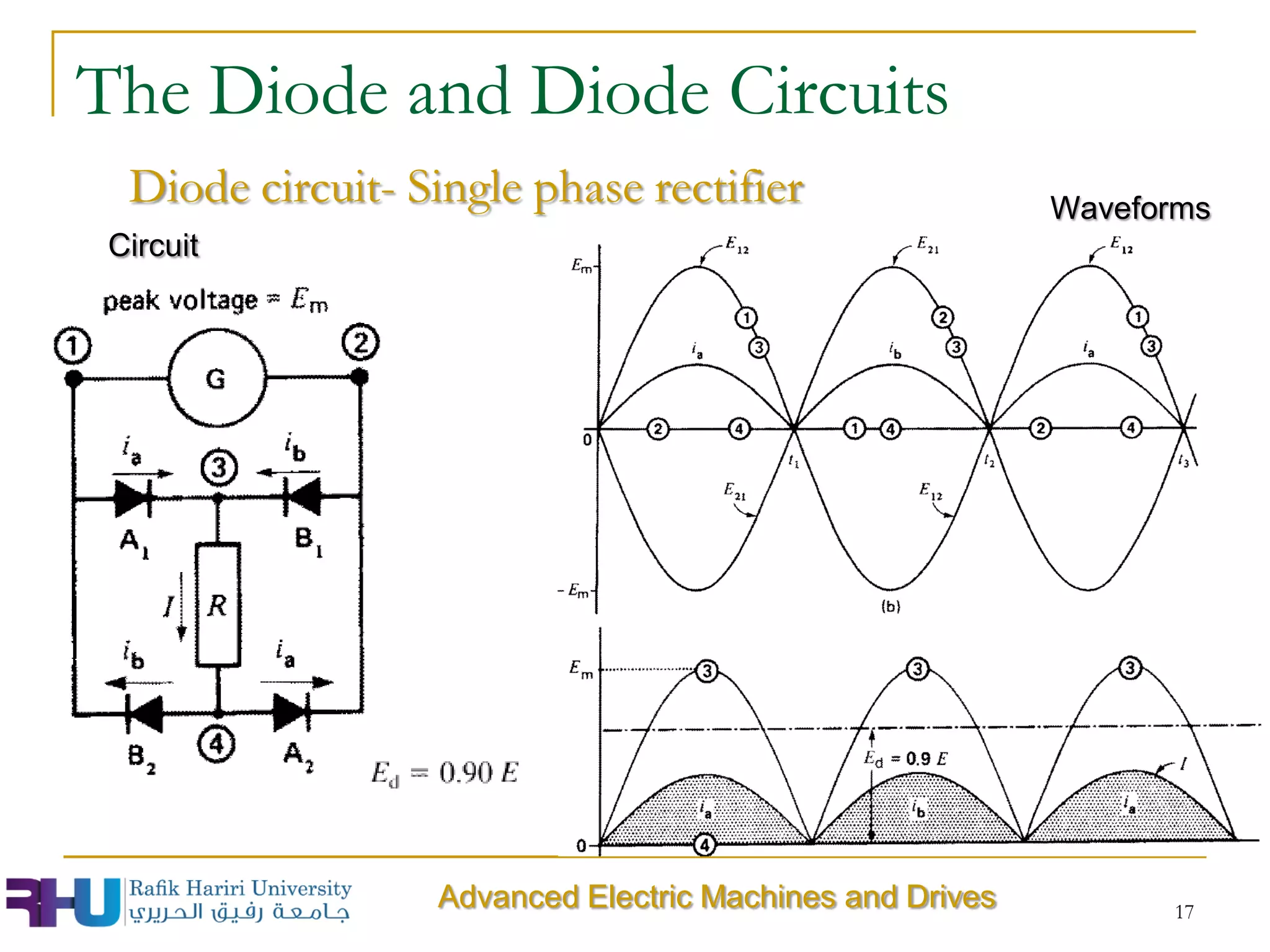
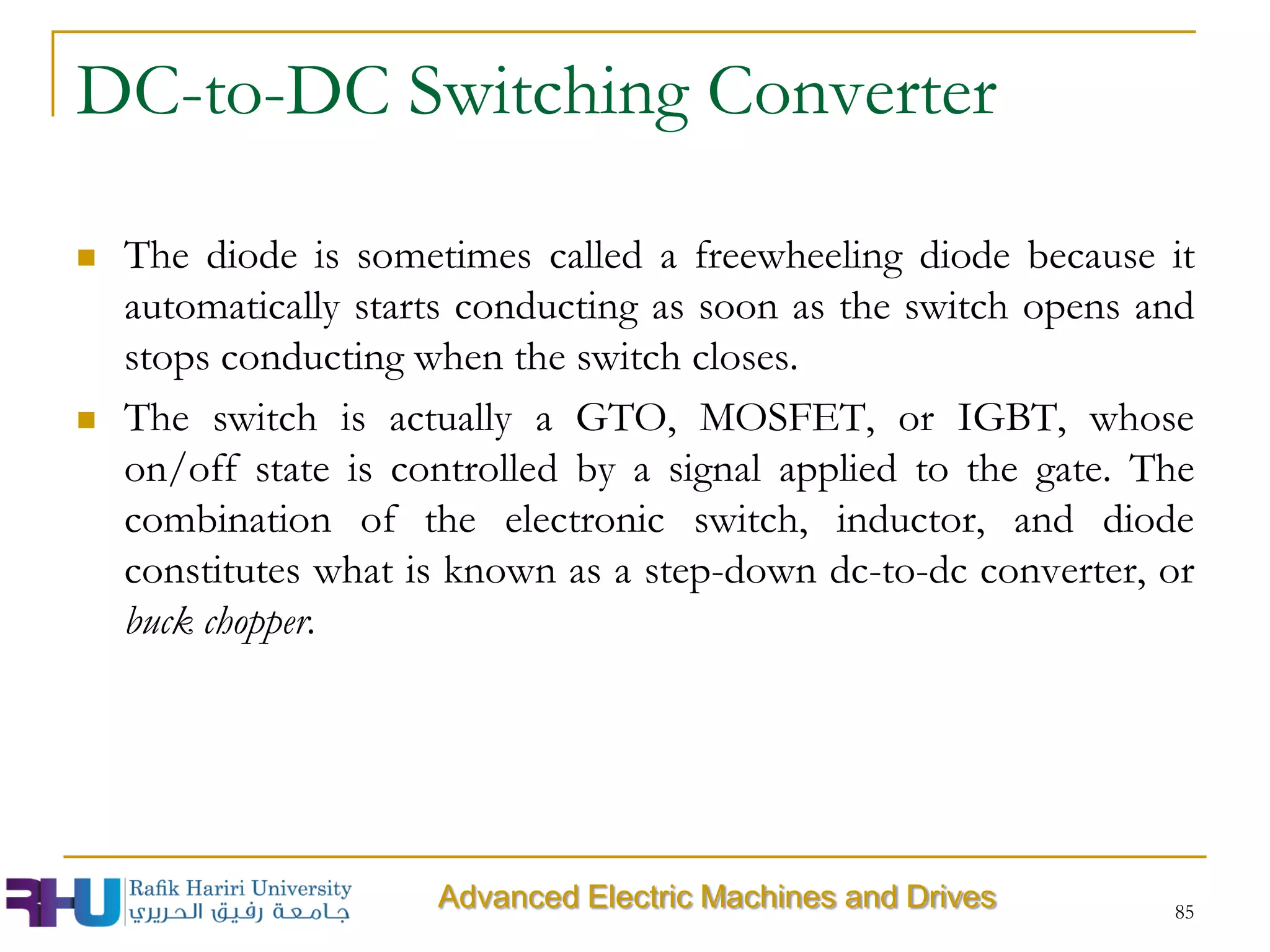
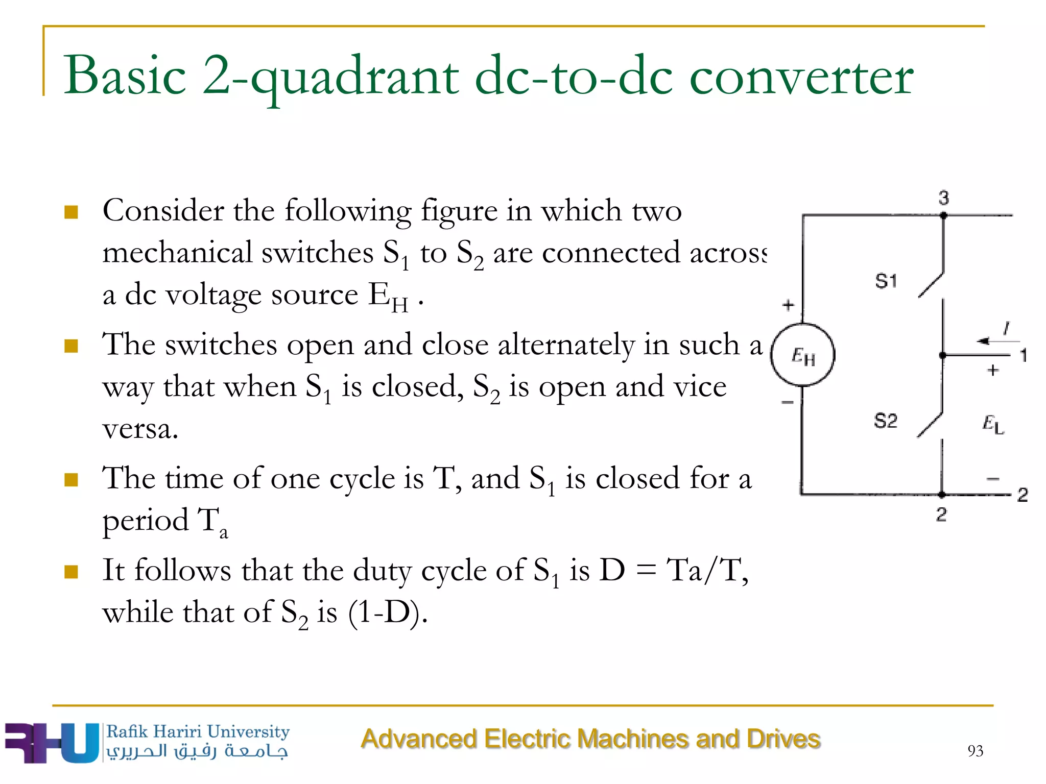
![ The greater the amount of energy stored in the filter, the better is the
filtering action. In the case of a bridge rectifier using an inductor, the
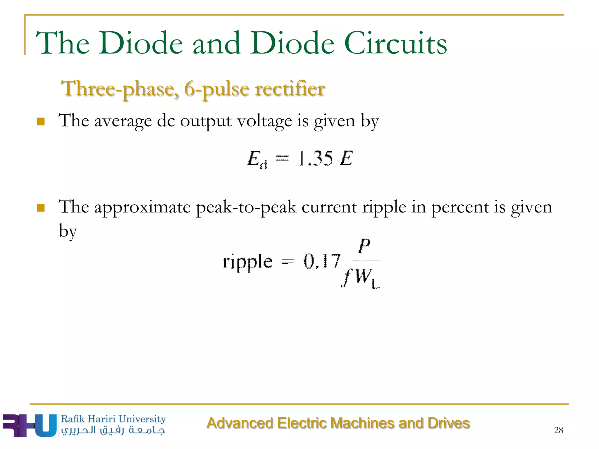
peak-to-peak ripple in percent is given by:
ripple peak-to-peak current as a percent of the dc current [%]
WL = dc energy stored in the smoothing inductor [J]
P = dc power drawn by the load [W]
f = frequency of the source [Hz]
20
The Diode and Diode Circuits
Filters
Advanced Electric Machines and Drives](https://image.slidesharecdn.com/elec581-chapter2-fundamentalelementsofpowereletronics-140501082015-phpapp02/75/Elec581-chapter-2-fundamental-elements-of-power-eletronics-20-2048.jpg)


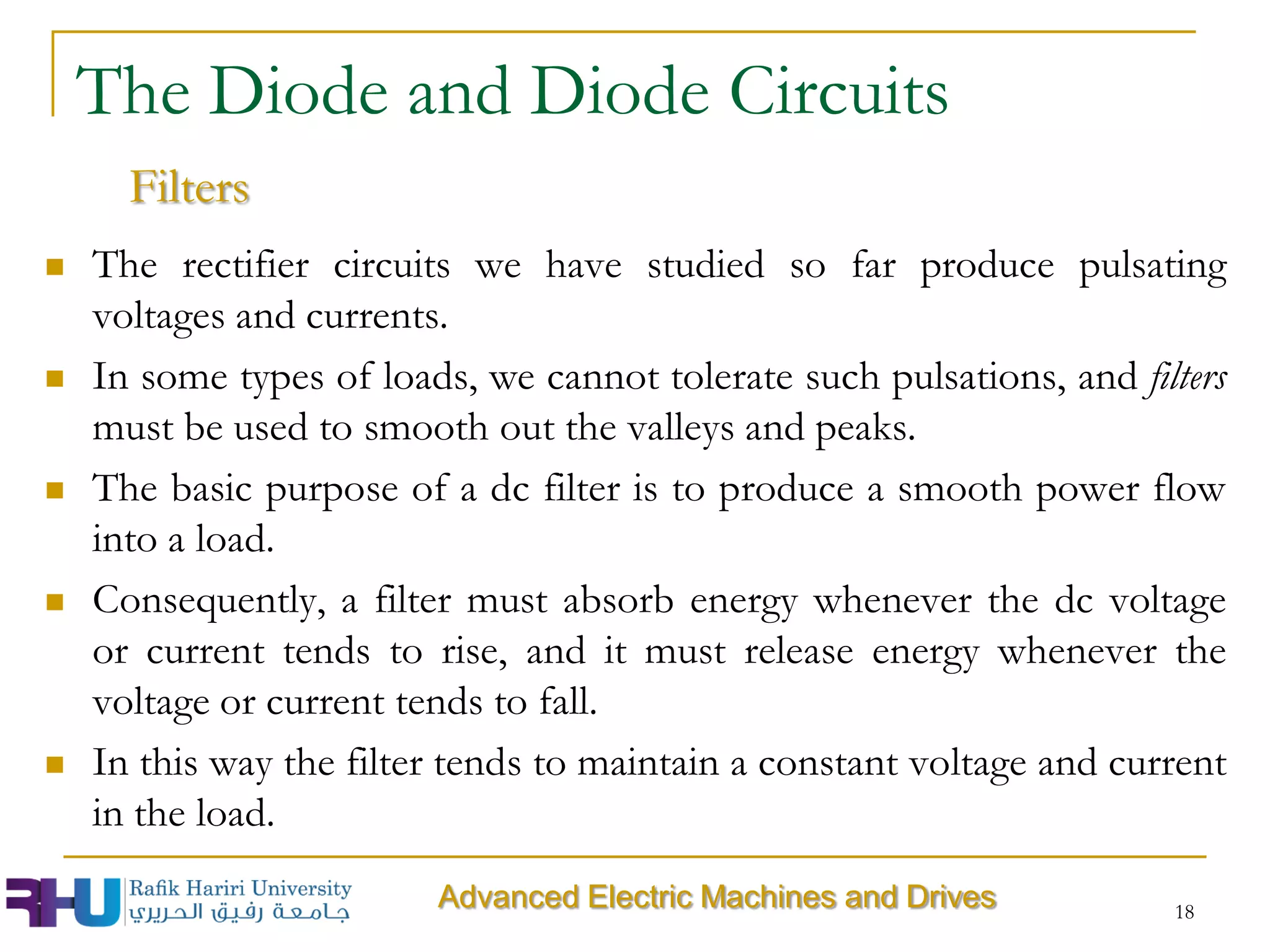
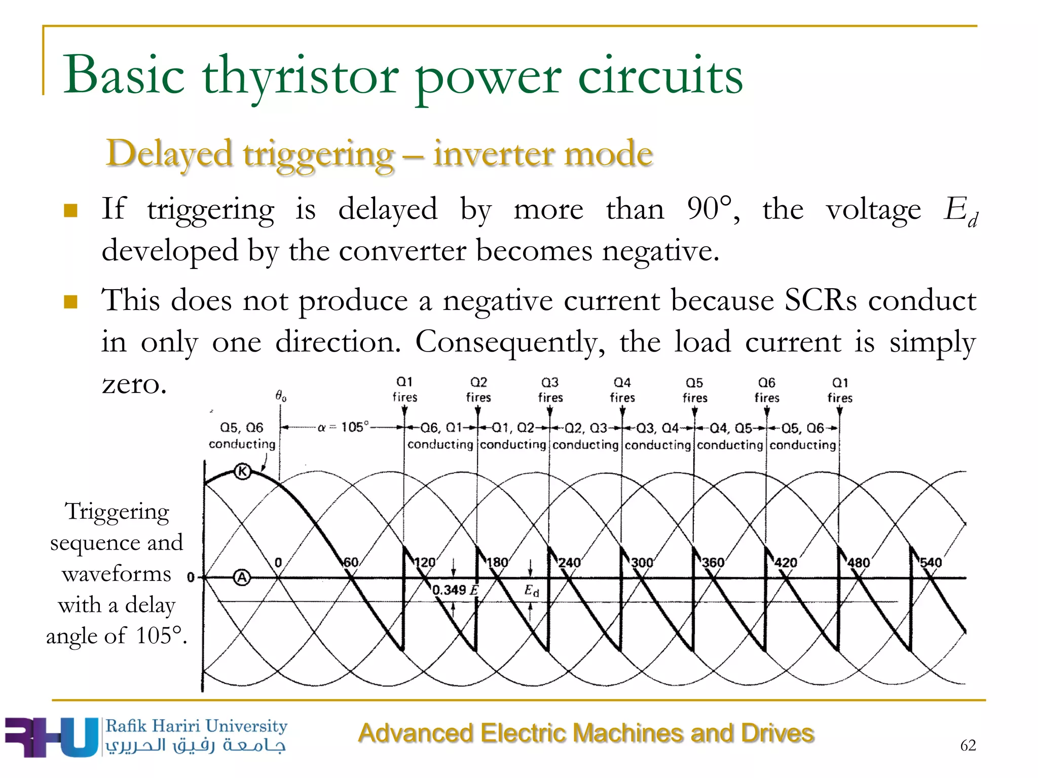
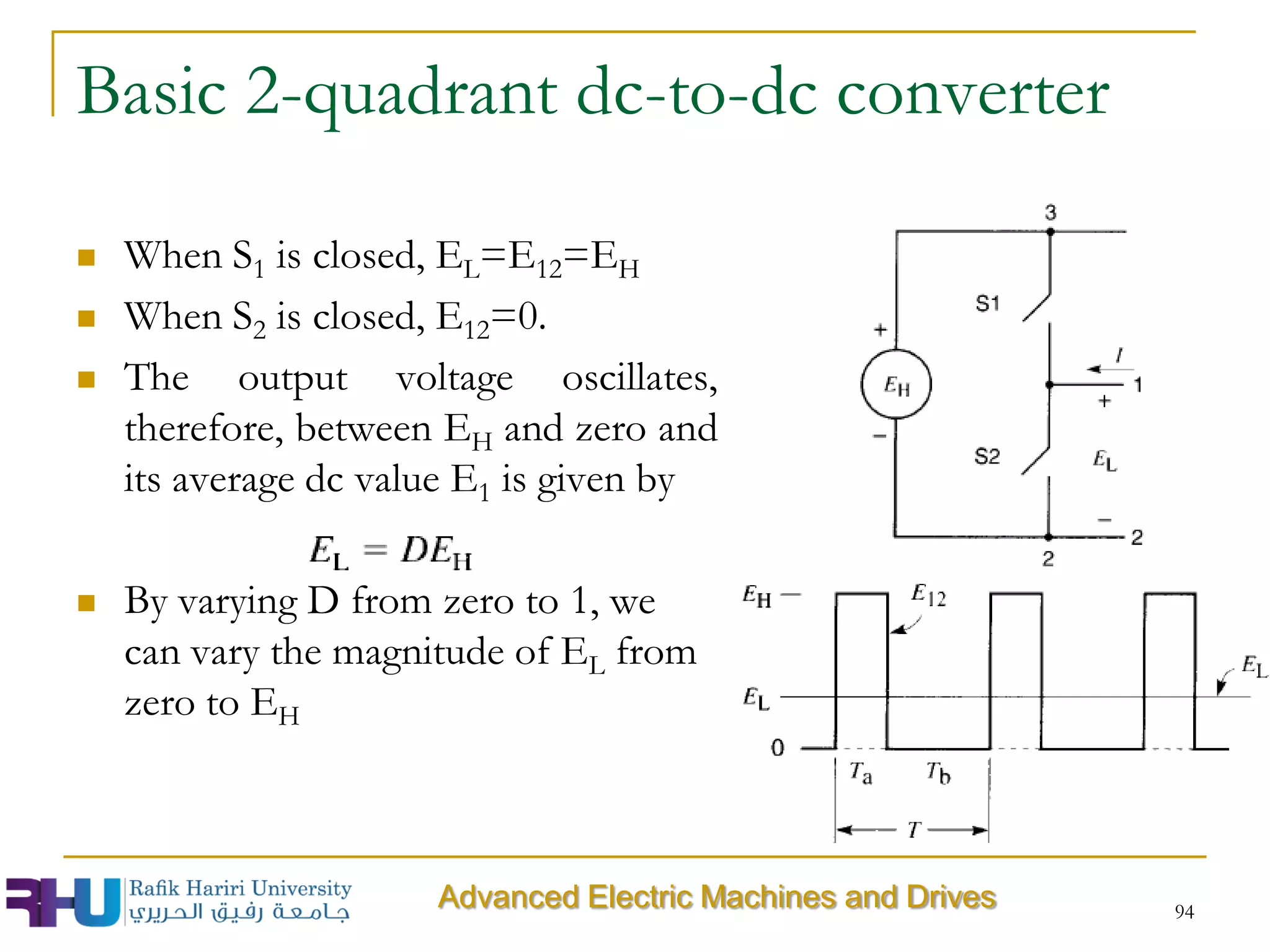
![Exercise
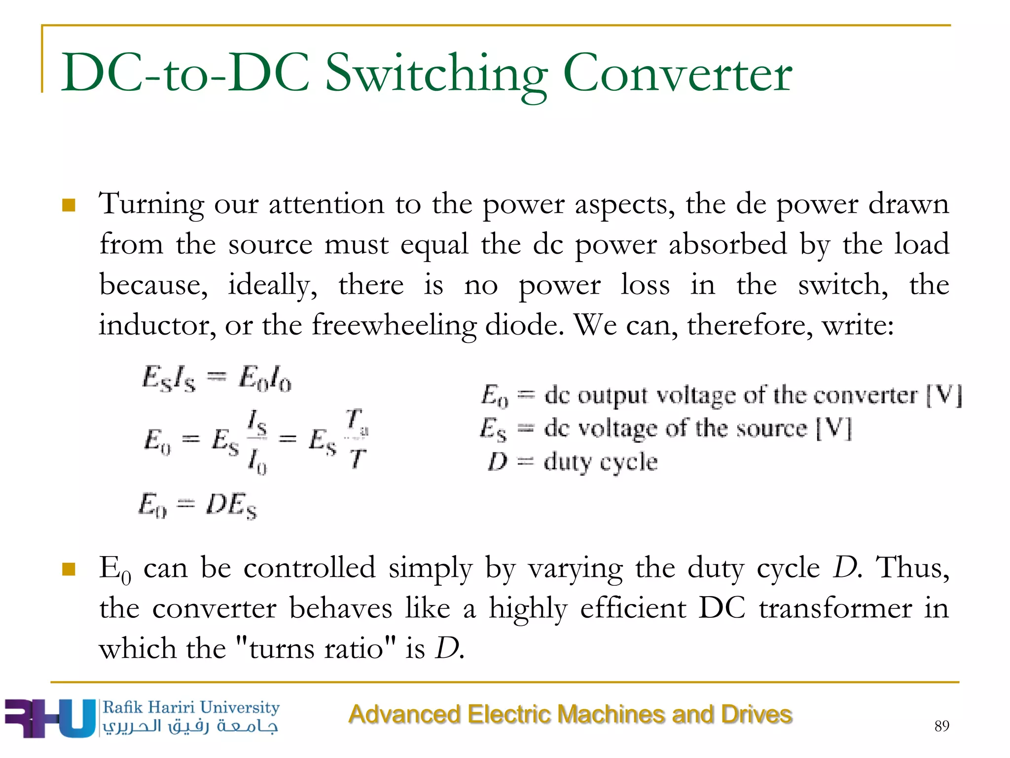
The 3-phase converter of the following figure is connected to a
3-phase 480V, 60 Hz source. The load consists of a 500 V dc
source having an internal resistance of 2Ω. Calculate the power
supplied to the load for triggering delays of (a) ]5° and (b) 75°.
61
Advanced Electric Machines and Drives](https://image.slidesharecdn.com/elec581-chapter2-fundamentalelementsofpowereletronics-140501082015-phpapp02/75/Elec581-chapter-2-fundamental-elements-of-power-eletronics-61-2048.jpg)

This document discusses fundamental concepts of power electronics including potential levels in circuits, voltage across circuit elements like switches, resistors, inductors and capacitors. It also covers diodes and their behavior as switches based on forward or reverse bias. Diode circuits like rectifiers and filters are described. Thyristors are then introduced as switches whose conduction can be controlled by a gate signal. Basic thyristor circuits include controlled rectifiers supplying passive or active loads.


