Downloaded 91 times


![References & Books
[1] Finney D., The Power Thyristor and its Applications, p. 35, Toronto,
McGraw-Hill Book Company Limited, 1980.
[2] Mahmud S. A., Murtala B. Z. A., Kolo J.G., Leonardo Journal of
Sciences, 11, p. 41-50, 2007.
[3] Remote Control System RC-5 Including Command Tables, Philips
Semiconductors, December 1992, Publication No. 9388706 23011
[4] Delgado, A. R., Picking, R., & Grout, V. (2006) Remote-controlled
home automation systems with different network technologies.
Proceedings of the 6th International Network Conference (INC 2006),
University of Plymouth, 11-14 July 2006, pp. 357-366.
[5[ Muhammad Ali Mazidi, Janice Gillespie Mazidi & Rolin D. McKinley
“8051 Microcontroller and Embedded Systems”, 2006
[6] Kenneth J. Ayala, “The 8051 microcontroller” 2008](https://image.slidesharecdn.com/new-final-160418174257/75/IR-remote-control-system-17-2048.jpg)


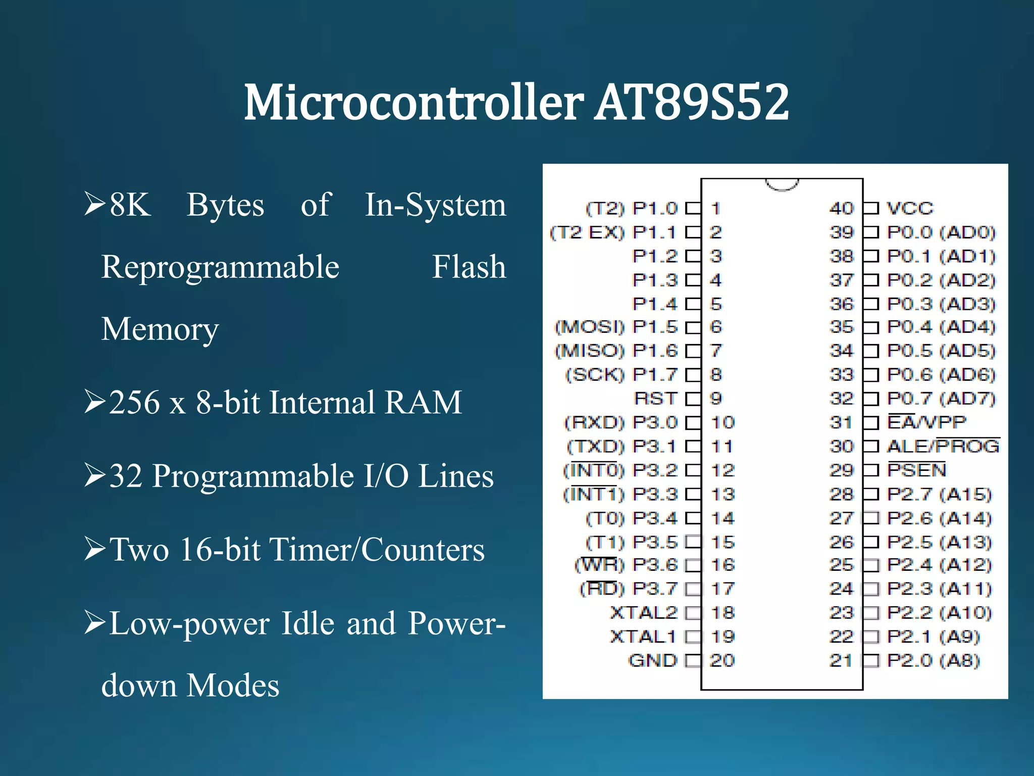
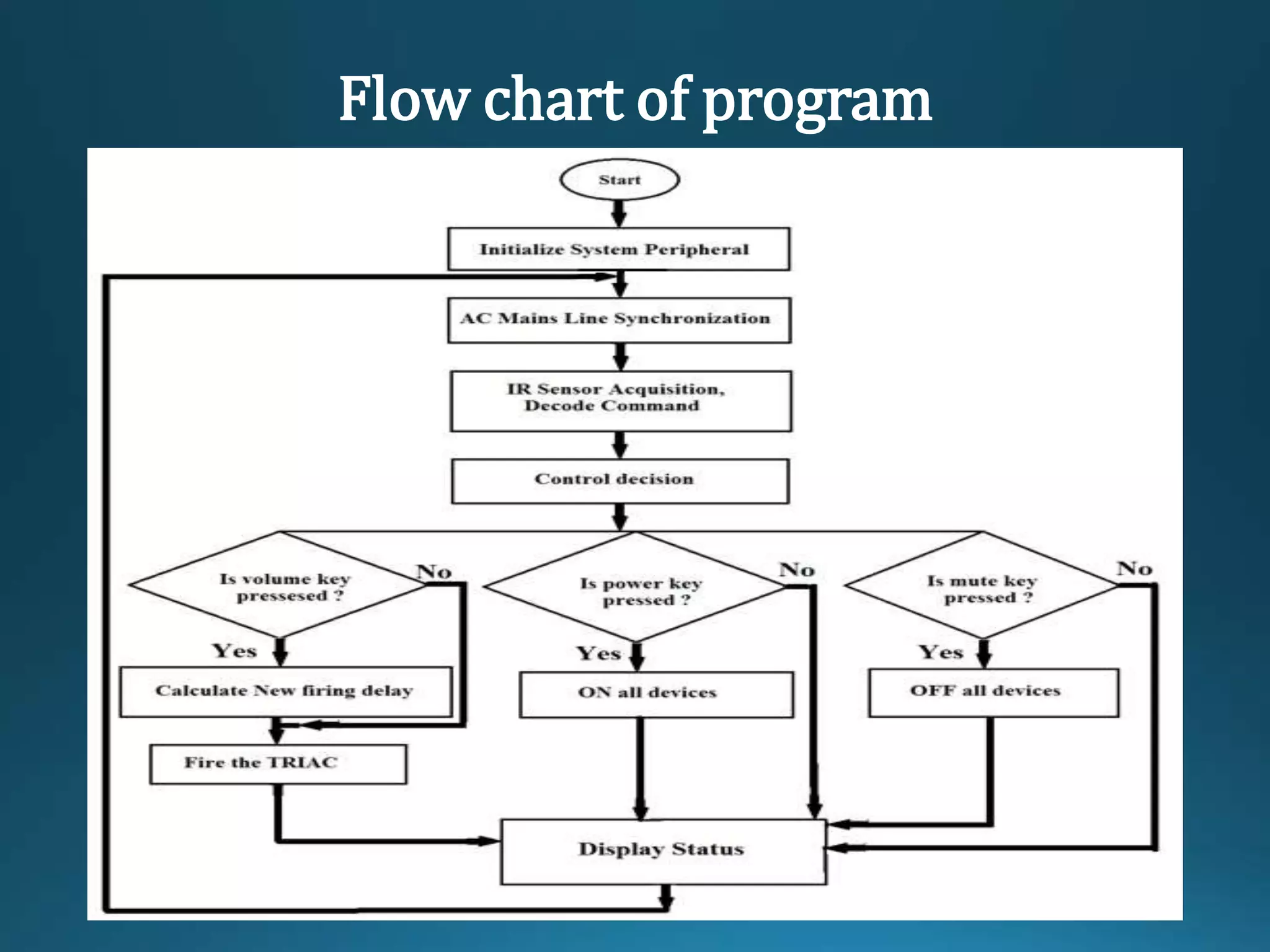
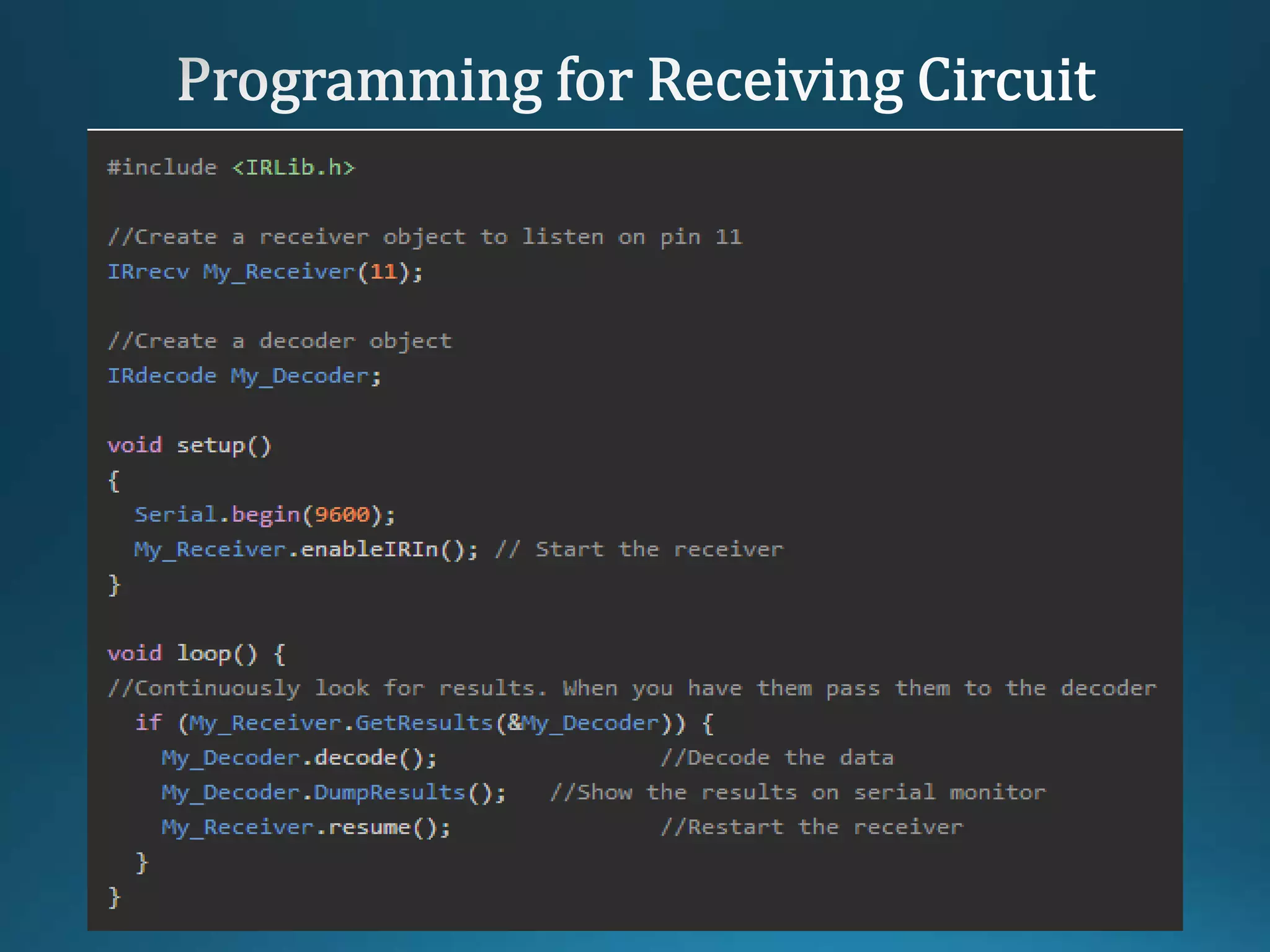
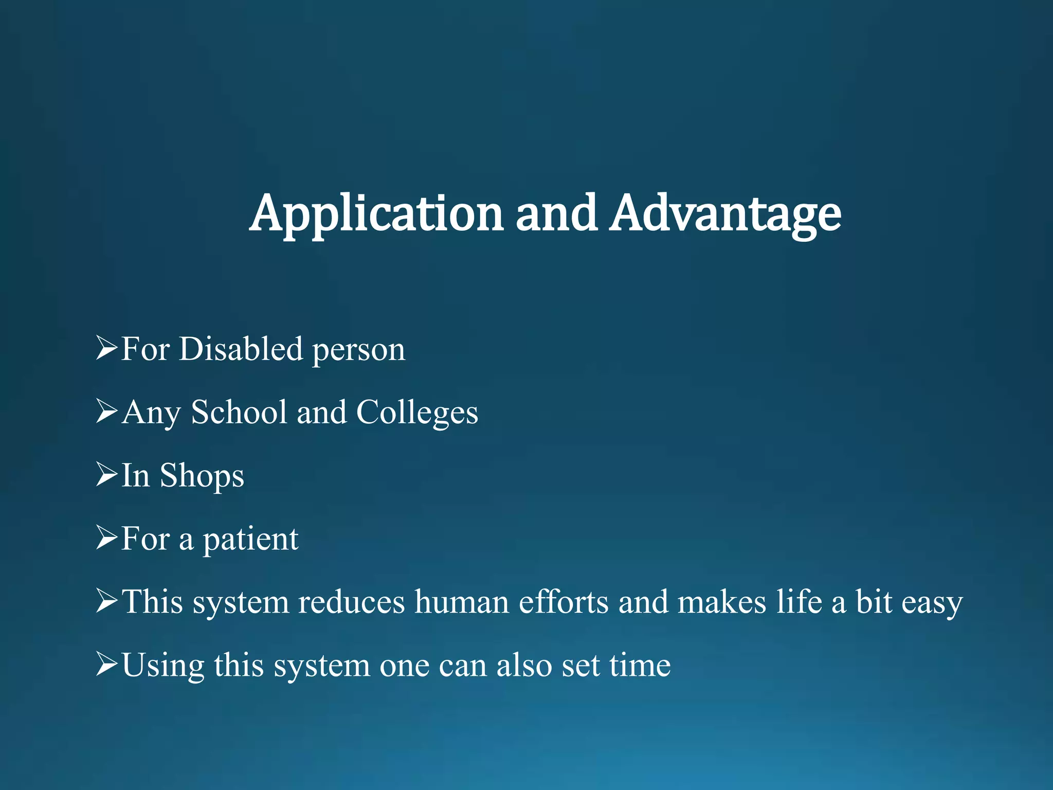
This document describes an infrared remote control system using a microcontroller. It consists of the following components: an infrared sensor, microcontroller, EEPROM, opto-isolator, dimmer IC, TRIAC, and LCD. The infrared sensor receives signals from the remote and sends them to the microcontroller. The microcontroller then processes the signals and uses the other components to control electrical devices, such as turning them on and off. The system allows disabled people and others to control devices remotely with infrared signals for convenience.