Download to read offline

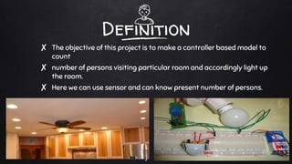

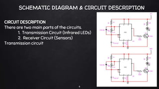
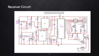

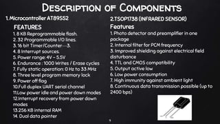


The document presents a project on an automatic room light controller with a bidirectional visitor counter, which uses infrared sensors and a microcontroller to count occupants and control lighting in a room. The system increments a counter when someone enters, activates the lights, and decrements the counter upon exit, ensuring lights are turned off only when the room is empty. It includes a detailed circuit description, components used, and potential applications for automation in home and office environments.


![Automaticroomlightcontroller[1]](https://cdn.slidesharecdn.com/ss_thumbnails/automaticroomlightcontroller1-150717125301-lva1-app6892-thumbnail.jpg?width=640&height=640&fit=bounds)


