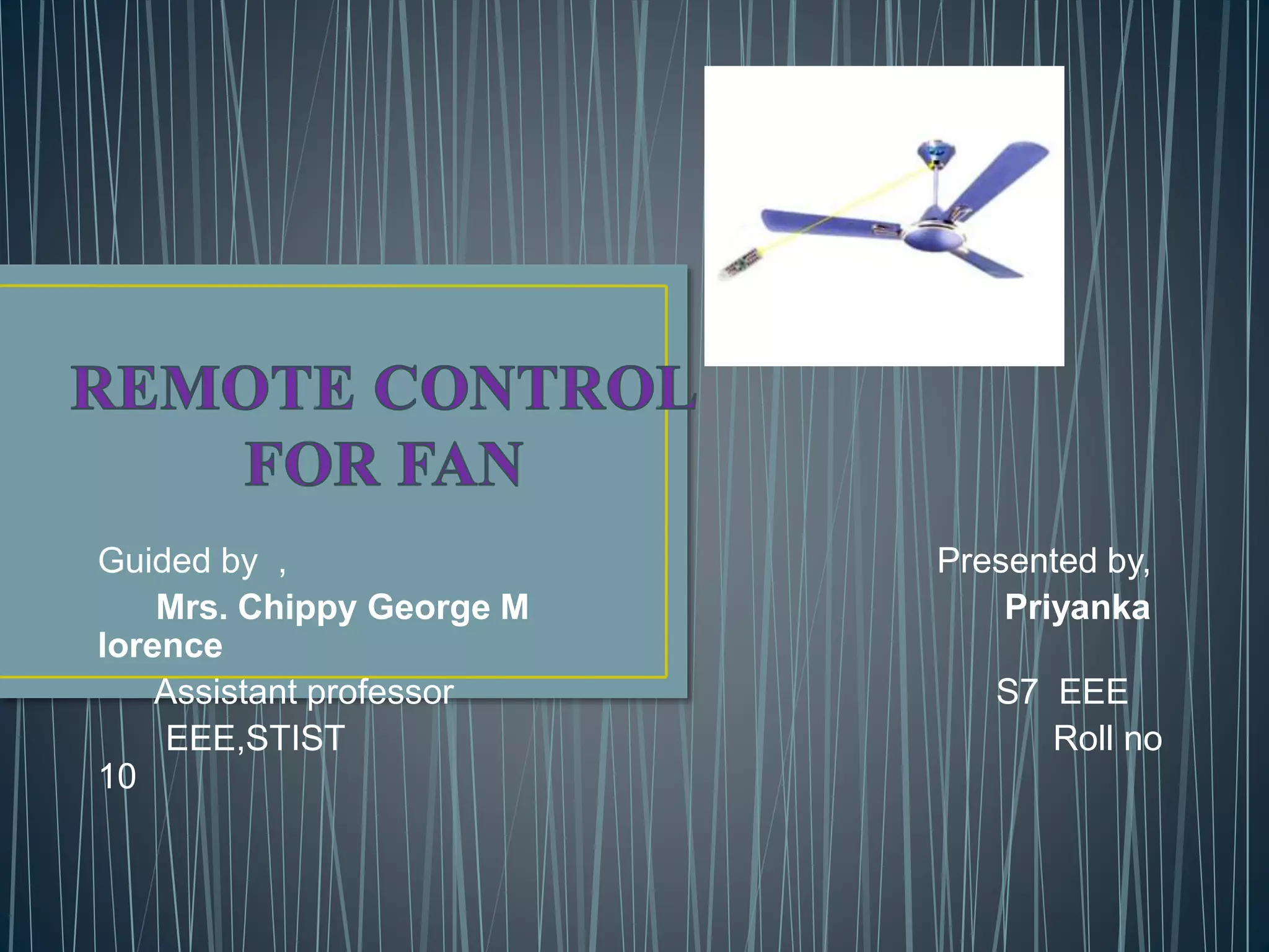
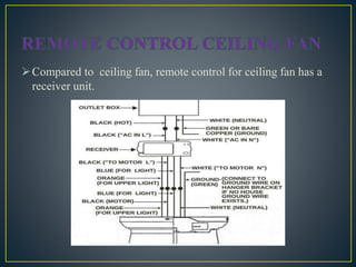
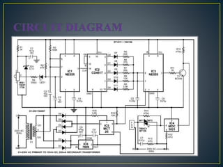
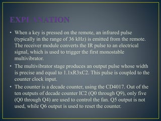
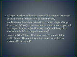
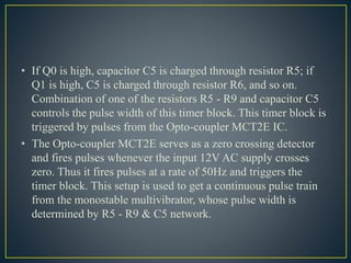
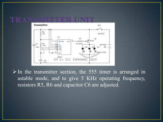
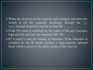
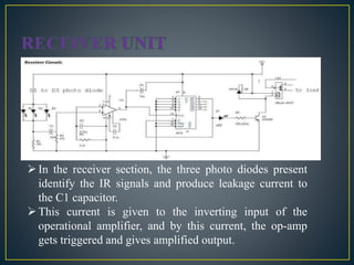
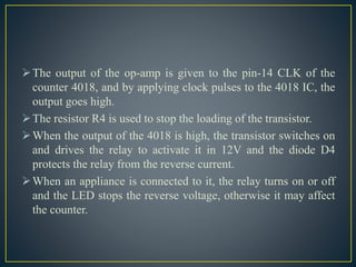
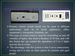
Guided by , Presented by,
Mrs. Chippy George M Priyanka
lorence
Assistant professor S7 EEE
EEE,STIST Roll no
10
 INTRODUCTION
 REMOTE CONTROL FOR CEILING FAN
CIRCUIT OF THE RECEIVER
EXPLANATION
 REMOTE CONTROL SWITCHES FOR FAN AND LIGHT
 BLOCK DIAGRAM
 EXPLANATION OF BLOCK DIAGRAM
 TRANSMITTER UNIT
 RECEIVER UNIT
 REMOTE CONTROL SWITCH BOARD
 APPLICATIONS
 ADVANTAGES
 DISADVANTAGES
 CONCLUSIONS
 REFERENCES
Remote control for fan provide comfort and convenience to on
or off and control them according to our need.
Operating conventional wall switches is difficult for elderly
and handicapped people. Remote control helps in controlling
the appliances from a distance.
Remote control provides a system simple to understand and
easy to operate.
Remote control switches are also available for controlling fan.
Compared to ordinary fan , remote control for fan consists of a
receiver to receive the transmitted rays from the remote.
Compared to ceiling fan, remote control for ceiling fan has a
receiver unit.
• When a key is pressed on the remote, an infrared pulse
(typically in the range of 36 kHz) is emitted from the remote.
The receiver module converts the IR pulse to an electrical
signal, which is used to trigger the first monostable
multivibrator.
• The multivibrator stage produces an output pulse whose width
is precise and equal to 1.1xR3xC2. This pulse is coupled to the
counter clock input.
• The counter is a decade counter, using the CD4017. Out of the
ten outputs of decade counter IC2 (Q0 through Q9), only five
(Q0 through Q4) are used to control the fan. Q5 output is not
used, while Q6 output is used to reset the counter.
• As a pulse arrives at the clock input of the counter, the output
changes from its present state to the next state.
• As the remote button are pressed, the counter output changes
from (say,) Q0 to Q5. Now, when the remote button is pressed,
the output changes to Q6. However, as Q6 and Reset pin is
shorted on the IC, the output resets to Q0.
• A second NE555 timer IC is also wired as a monostable
multivibrator. The output from the counter is applied to
resistors R5 through R9.
• If Q0 is high, capacitor C5 is charged through resistor R5; if
Q1 is high, C5 is charged through resistor R6, and so on.
Combination of one of the resistors R5 - R9 and capacitor C5
controls the pulse width of this timer block. This timer block is
triggered by pulses from the Opto-coupler MCT2E IC.
• The Opto-coupler MCT2E serves as a zero crossing detector
and fires pulses whenever the input 12V AC supply crosses
zero. Thus it fires pulses at a rate of 50Hz and triggers the
timer block. This setup is used to get a continuous pulse train
from the monostable multivibrator, whose pulse width is
determined by R5 - R9 & C5 network.
• The pulse train is supplied to an Opto-isolator, MOC3021
(IC4). The MOC3021 drives the triac BT136. Resistor R13 and
capacitor C7 combination is used as snubber network for the
triac. The triac network ultimately drives the fan.
• As keys are pressed on the remote, the output from CD4017
advances from Q0 to Q4. The width of the pulse from the
second multivibrator decreases, firing angle of the triac
increases and in turn the speed of the fan increases. Thus the
speed of the fan increases when we press any button on the
remote control. When the output of CD4017 is at Q5, there is
no output and fan is turned off.
• The circuit is powered by regulated 9V. The 230V AC is
stepped down by transformer X1 to deliver a secondary output
of 12V-0-12V. The transformer output is rectified by full-wave
rectifier comprising diodes D1 and D2, filtered by capacitor C9
and regulated by LM7809 regulator to provide 9V regulated
output.
In the transmitter section, we have NE555 timer which is
configured in astable mode and infrared LEDs whose infrared
rays are directed by the concave lens and the source of power is
from 9V battery.
When the switch is closed, the power from the battery turns on
the NE555 timer which will act as an astable multivibrator. The
infrared LEDs which are connected to the output of NE555 will
get high and produce the infrared beam through the concave
lens.
 When the infrared beam from the transmitter is reached by the receiver section, the photo LEDs will receive the infrared beam
and charge the capacitor which will increase the input voltage of one pin of operational amplifier and high output is generated.
This high output is given to the 4018 Counter as input and counter will drive the load through a relay to switch on or switch
off accordingly.
In the transmitter section, the 555 timer is arranged in
astable mode, and to give 5 KHz operating frequency,
resistors R5, R6 and capacitor C6 are adjusted.
When the switch is on the capacitor gets charged, and when the
switch is off the capacitor discharges through the 555
timer internal transistors and the resistor R6.
If the 555 timer is switched on, the output of the pin3 becomes
high and this activates the transistor SK 100.
R7 is used to stop the loading of transistor. If the transistor is
switched on, the IR diodes produce a high-intensity infrared
beam which is given to the photo diodes of the receiver.
In the receiver section, the three photo diodes present
identify the IR signals and produce leakage current to
the C1 capacitor.
This current is given to the inverting input of the
operational amplifier, and by this current, the op-amp
gets triggered and gives amplified output.
 All the other remaining pins are connected to the ground.
The resistor R2 and the capacitor C2 are used to stop the
unwanted signals from triggering the op-amp, and the capacitor
C3 is used for high gain which is used as a comparator
amplifier
 All the other remaining pins are connected to the ground.
The resistor R2 and the capacitor C2 are used to stop the
unwanted signals from triggering the op-amp, and the capacitor
C3 is used for high gain which is used as a comparator
amplifier
The output of the op-amp is given to the pin-14 CLK of the
counter 4018, and by applying clock pulses to the 4018 IC, the
output goes high.
The resistor R4 is used to stop the loading of the transistor.
When the output of the 4018 is high, the transistor switches on
and drives the relay to activate it in 12V and the diode D4
protects the relay from the reverse current.
When an appliance is connected to it, the relay turns on or off
and the LED stops the reverse voltage, otherwise it may affect
the counter.
Remote control switch board can be used in different
applications such as in home appliances, office
equipment’s, restaurants, hospitals, etc.
This type of switch board is used for controlling on and off
switches of lights, fans from a distance of 30 feet, and with
this board one can control the operations of 3 to 5 lights
and one fan at a time.
 The advantage with this system is that it saves unnecessary
wiring and it is also an ideal option for patients and aged
people.
Remote controlled fan regulator is used to control the speed of
fan from bed or couch.
The same circuit find its use to control the intensity of light at
various level.
The range of IR remote is very large and can be controlled
across a large room.
There is no subsequent cost after installation.
Circuit is simple to use and efficient.
It is cheap and hence very economic.
DISADVANTAGES
IR radiation from remote is designed to spread to large area.
If the regulator sensor is placed near a television or ac then
the speed may be changed whenever the remote is pressed or
controlling the other device
Remote control provides comfort and convenience to ON and
OFF a electric appliance.
The system response favourably and alters the voltage
smoothly when any button of modern day remote control is
pressed. The receiver transmitter maximum distance is
approximately 10m.
 The normal ceiling fan can be converted into an remote control
ceiling fan by installing a receiver unit.
Remote control switches are also available which helps in
controlling lights and fan.
Remote control appliances are useful for elderly and
handicapped people.
[1] "DC vs AC Ceiling Fans". www.hunterfan.co.uk. Retrieved 25 May 2015.
[2] Savage, Adam (co-host); Hyneman, Jamie (co-host); Chapman, Scottie (Build Team); Belleci, Tory (Build Team); Byron,
Kari (Build Team) (December 5, 2004). "Ming Dynasty Astronaut". MythBusters. Season 2. Episode 24. Begins at 25:45.
Discovery.
[3] Gromicko, Nick. "Ceiling Fan Inspection". International Association of Certified Home Inspectors. Retrieved May 31, 2013.
[4] K. J. Ayala 8051 Microcontroller, Architecture, Programming & Applications, Second Edition, 1997, Singapore, Penram
International Publishing Pvt. Ltd. (2005)
[5] Atmel Corporation, 8-bit Microcontroller with 8K Bytes Flash
http://www.atmel.com/dyn/resources/prod_documents/doc0313.pdf
REMOTE CONTROL FOR FAN  SLIDE SHARE

REMOTE CONTROL FOR FAN SLIDE SHARE

  • 1.
    Guided by ,Presented by, Mrs. Chippy George M Priyanka lorence Assistant professor S7 EEE EEE,STIST Roll no 10
  • 2.
     INTRODUCTION  REMOTECONTROL FOR CEILING FAN CIRCUIT OF THE RECEIVER EXPLANATION  REMOTE CONTROL SWITCHES FOR FAN AND LIGHT  BLOCK DIAGRAM  EXPLANATION OF BLOCK DIAGRAM  TRANSMITTER UNIT  RECEIVER UNIT  REMOTE CONTROL SWITCH BOARD  APPLICATIONS  ADVANTAGES  DISADVANTAGES  CONCLUSIONS  REFERENCES
  • 3.
    Remote control forfan provide comfort and convenience to on or off and control them according to our need. Operating conventional wall switches is difficult for elderly and handicapped people. Remote control helps in controlling the appliances from a distance. Remote control provides a system simple to understand and easy to operate. Remote control switches are also available for controlling fan. Compared to ordinary fan , remote control for fan consists of a receiver to receive the transmitted rays from the remote.
  • 4.
    Compared to ceilingfan, remote control for ceiling fan has a receiver unit.
  • 7.
    • When akey is pressed on the remote, an infrared pulse (typically in the range of 36 kHz) is emitted from the remote. The receiver module converts the IR pulse to an electrical signal, which is used to trigger the first monostable multivibrator. • The multivibrator stage produces an output pulse whose width is precise and equal to 1.1xR3xC2. This pulse is coupled to the counter clock input. • The counter is a decade counter, using the CD4017. Out of the ten outputs of decade counter IC2 (Q0 through Q9), only five (Q0 through Q4) are used to control the fan. Q5 output is not used, while Q6 output is used to reset the counter.
  • 8.
    • As apulse arrives at the clock input of the counter, the output changes from its present state to the next state. • As the remote button are pressed, the counter output changes from (say,) Q0 to Q5. Now, when the remote button is pressed, the output changes to Q6. However, as Q6 and Reset pin is shorted on the IC, the output resets to Q0. • A second NE555 timer IC is also wired as a monostable multivibrator. The output from the counter is applied to resistors R5 through R9.
  • 9.
    • If Q0is high, capacitor C5 is charged through resistor R5; if Q1 is high, C5 is charged through resistor R6, and so on. Combination of one of the resistors R5 - R9 and capacitor C5 controls the pulse width of this timer block. This timer block is triggered by pulses from the Opto-coupler MCT2E IC. • The Opto-coupler MCT2E serves as a zero crossing detector and fires pulses whenever the input 12V AC supply crosses zero. Thus it fires pulses at a rate of 50Hz and triggers the timer block. This setup is used to get a continuous pulse train from the monostable multivibrator, whose pulse width is determined by R5 - R9 & C5 network.
  • 10.
    • The pulsetrain is supplied to an Opto-isolator, MOC3021 (IC4). The MOC3021 drives the triac BT136. Resistor R13 and capacitor C7 combination is used as snubber network for the triac. The triac network ultimately drives the fan. • As keys are pressed on the remote, the output from CD4017 advances from Q0 to Q4. The width of the pulse from the second multivibrator decreases, firing angle of the triac increases and in turn the speed of the fan increases. Thus the speed of the fan increases when we press any button on the remote control. When the output of CD4017 is at Q5, there is no output and fan is turned off.
  • 11.
    • The circuitis powered by regulated 9V. The 230V AC is stepped down by transformer X1 to deliver a secondary output of 12V-0-12V. The transformer output is rectified by full-wave rectifier comprising diodes D1 and D2, filtered by capacitor C9 and regulated by LM7809 regulator to provide 9V regulated output.
  • 13.
    In the transmittersection, we have NE555 timer which is configured in astable mode and infrared LEDs whose infrared rays are directed by the concave lens and the source of power is from 9V battery. When the switch is closed, the power from the battery turns on the NE555 timer which will act as an astable multivibrator. The infrared LEDs which are connected to the output of NE555 will get high and produce the infrared beam through the concave lens.
  • 14.
     When theinfrared beam from the transmitter is reached by the receiver section, the photo LEDs will receive the infrared beam and charge the capacitor which will increase the input voltage of one pin of operational amplifier and high output is generated. This high output is given to the 4018 Counter as input and counter will drive the load through a relay to switch on or switch off accordingly.
  • 15.
    In the transmittersection, the 555 timer is arranged in astable mode, and to give 5 KHz operating frequency, resistors R5, R6 and capacitor C6 are adjusted.
  • 16.
    When the switchis on the capacitor gets charged, and when the switch is off the capacitor discharges through the 555 timer internal transistors and the resistor R6. If the 555 timer is switched on, the output of the pin3 becomes high and this activates the transistor SK 100. R7 is used to stop the loading of transistor. If the transistor is switched on, the IR diodes produce a high-intensity infrared beam which is given to the photo diodes of the receiver.
  • 17.
    In the receiversection, the three photo diodes present identify the IR signals and produce leakage current to the C1 capacitor. This current is given to the inverting input of the operational amplifier, and by this current, the op-amp gets triggered and gives amplified output.
  • 18.
     All theother remaining pins are connected to the ground. The resistor R2 and the capacitor C2 are used to stop the unwanted signals from triggering the op-amp, and the capacitor C3 is used for high gain which is used as a comparator amplifier  All the other remaining pins are connected to the ground. The resistor R2 and the capacitor C2 are used to stop the unwanted signals from triggering the op-amp, and the capacitor C3 is used for high gain which is used as a comparator amplifier
  • 19.
    The output ofthe op-amp is given to the pin-14 CLK of the counter 4018, and by applying clock pulses to the 4018 IC, the output goes high. The resistor R4 is used to stop the loading of the transistor. When the output of the 4018 is high, the transistor switches on and drives the relay to activate it in 12V and the diode D4 protects the relay from the reverse current. When an appliance is connected to it, the relay turns on or off and the LED stops the reverse voltage, otherwise it may affect the counter.
  • 20.
    Remote control switchboard can be used in different applications such as in home appliances, office equipment’s, restaurants, hospitals, etc. This type of switch board is used for controlling on and off switches of lights, fans from a distance of 30 feet, and with this board one can control the operations of 3 to 5 lights and one fan at a time.  The advantage with this system is that it saves unnecessary wiring and it is also an ideal option for patients and aged people.
  • 21.
    Remote controlled fanregulator is used to control the speed of fan from bed or couch. The same circuit find its use to control the intensity of light at various level.
  • 22.
    The range ofIR remote is very large and can be controlled across a large room. There is no subsequent cost after installation. Circuit is simple to use and efficient. It is cheap and hence very economic. DISADVANTAGES IR radiation from remote is designed to spread to large area. If the regulator sensor is placed near a television or ac then the speed may be changed whenever the remote is pressed or controlling the other device
  • 23.
    Remote control providescomfort and convenience to ON and OFF a electric appliance. The system response favourably and alters the voltage smoothly when any button of modern day remote control is pressed. The receiver transmitter maximum distance is approximately 10m.  The normal ceiling fan can be converted into an remote control ceiling fan by installing a receiver unit. Remote control switches are also available which helps in controlling lights and fan. Remote control appliances are useful for elderly and handicapped people.
  • 24.
    [1] "DC vsAC Ceiling Fans". www.hunterfan.co.uk. Retrieved 25 May 2015. [2] Savage, Adam (co-host); Hyneman, Jamie (co-host); Chapman, Scottie (Build Team); Belleci, Tory (Build Team); Byron, Kari (Build Team) (December 5, 2004). "Ming Dynasty Astronaut". MythBusters. Season 2. Episode 24. Begins at 25:45. Discovery. [3] Gromicko, Nick. "Ceiling Fan Inspection". International Association of Certified Home Inspectors. Retrieved May 31, 2013. [4] K. J. Ayala 8051 Microcontroller, Architecture, Programming & Applications, Second Edition, 1997, Singapore, Penram International Publishing Pvt. Ltd. (2005) [5] Atmel Corporation, 8-bit Microcontroller with 8K Bytes Flash http://www.atmel.com/dyn/resources/prod_documents/doc0313.pdf