This document summarizes various aircraft instrumentation systems including:
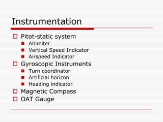
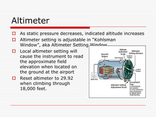
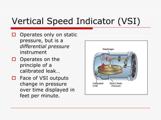
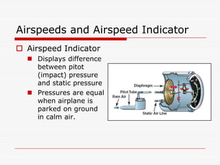
- The pitot-static system which includes the altimeter, vertical speed indicator, and airspeed indicator.
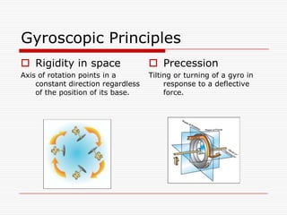
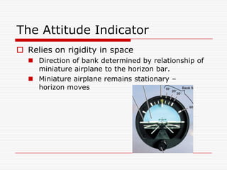
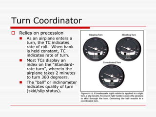
- Gyroscopic instruments like the turn coordinator, artificial horizon, and heading indicator.
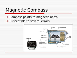
- Other instruments like the magnetic compass and outside air temperature gauge.
It provides details on how each instrument works and key terms related to altitude, airspeed, and gyroscopic principles.