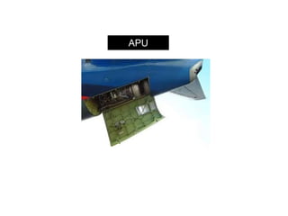
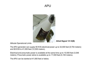
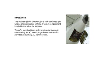
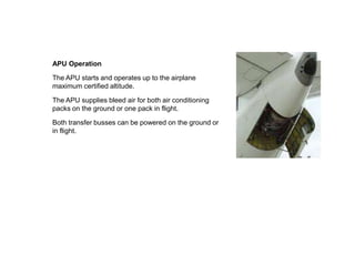
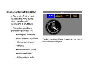
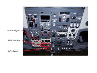
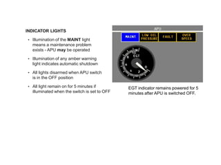
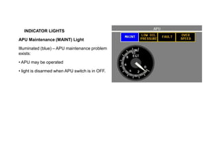
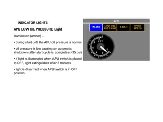
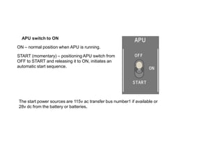
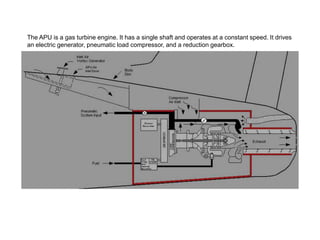
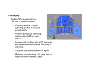
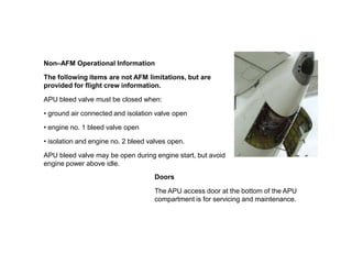
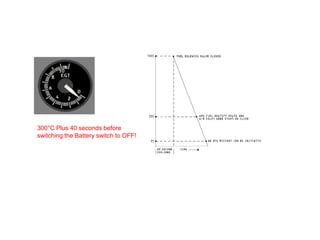
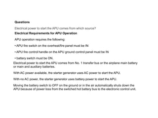
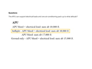
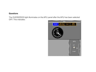
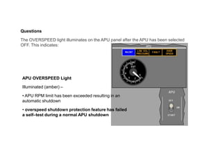
SlideShare a Scribd company logo
1 of 53
•B 737 NG Ground School.
See the aircraft study guide at www.theorycentre.com
The information contained here is for training purposes only. It is of a general nature it is
unamended and does not relate to any individual aircraft. The FCOM must be consulted for
up to date information on any particular aircraft.
B 737 NG Ground School.
APU
APU
Allied Signal 131-9(B)
Altitude Operational Limits
The APU generator can supply 90 KVA electrical power up to 32,000 feet (9,754 meters)
and 66 KVA to 41,000 feet (12,500 meters).
Electrical and pneumatic power is available at the same time up to 10,000 feet (3,048
meters). Pneumatic power alone is available up to 17,000 feet (5,183 meters).
The APU can be started at 41,000 feet or below.
Introduction
The auxiliary power unit (APU) is a self–contained gas
turbine engine installed within a fireproof compartment
located in the tail of the airplane.
The APU supplies bleed air for engine starting or air
conditioning. An AC electrical generator on the APU
provides an auxiliary AC power source.
APU Operation
The APU starts and operates up to the airplane
maximum certified altitude.
The APU supplies bleed air for both air conditioning
packs on the ground or one pack in flight.
Both transfer busses can be powered on the ground or
in flight.
Electronic Control Unit (ECU)
An electronic control unit (ECU) monitors and controls the APU. Automatic shutdown
protection is provided for overspeed conditions, low oil pressure, high oil temperature,
APU fire, fuel control unit failure, EGT exceedance, and other system faults monitored
by the ECU.
The ECU automatically controls APU speed through the electronic fuel control. If
speed or EGT exceed acceptable levels with the APU providing electrical load only,
some electrical load is shed. When electrical load and air extraction raise the EGT
above acceptable levels during engine starting, electrical load shedding occurs prior to
reducing bleed air.
When electrical load and air extraction raise the EGT above acceptable levels other
than during engine starting, the inlet guide vanes move toward a closed position,
reducing bleed air extraction while maintaining electrical load.
Electronic Control Unit (ECU)
• Electronic Control Unit
controls the APU during
start, steady state
operations & shutdown
• Protective shutdown
protection provided for:
• Overspeed conditions
• Low oil pressure (<35 psi)
• High oil temperature
• APU fire
• Fuel control unit failure
• EGT exceedance
• Other systems faults
The ECU receives 28v dc power from the 28v dc
switched hot battery bus.
Indicator lights
EGT Indicator
APU Switch
• INDICATOR LIGHTS lights
• Illumination of the MAINT light
means a maintenance problem
exists - APU may be operated
• Illumination of any amber warning
light indicates automatic shutdown
• All lights disarmed when APU switch
is in the OFF position
• All light remain on for 5 minutes if
illuminated when the switch is set to OFF
EGT indicator remains powered for 5
minutes after APU is switched OFF.
INDICATOR LIGHTS
APU Maintenance (MAINT) Light
Illuminated (blue) – APU maintenance problem
exists:
• APU may be operated
• light is disarmed when APU switch is in OFF.
INDICATOR LIGHTS
APU LOW OIL PRESSURE Light
Illuminated (amber) –
• during start until the APU oil pressure is normal
• oil pressure is low causing an automatic
shutdown (after start cycle is complete) (<35 psi)
• if light is illuminated when APU switch is placed
to OFF, light extinguishes after 5 minutes
• light is disarmed when APU switch is in OFF
position.
INDICATOR LIGHTS
APU FAULT Light
Illuminated (amber) –
• a malfunction exists causing APU to initiate an
automatic shutdown
• if light is illuminated when APU switch is placed
to OFF, light extinguishes after 5 minutes
• light is disarmed when APU switch is in OFF
position.
APU FAULT Light
These are the protective shutdowns that cause a fault light:
APU fuel valve shutdown
DC power loss shutdown
ECU shutdown
Fire shutdown
Inlet door shutdown
Inlet overheat shutdown
Loss of EGT shutdown
Loss of speed shutdown
No acceleration shutdown
No APU rotation shutdown
No flame shutdown
Oil filter shutdown
Oil temperature shutdown
Overtemperature shutdown
Reverse flow shutdown
Sensor failure
Underspeed shutdown
INDICATOR LIGHTS
APU OVERSPEED Light
Illuminated (amber) –
• APU RPM limit has been exceeded resulting in
an automatic shutdown
• overspeed shutdown protection feature has
failed a self–test during a normal APU shutdown
The ECU does the overspeed circuit test during every normal APU shutdown.
An overspeed shutdown occurs if the APU speed is more than 106 percent.
When the ECU does a protective shutdown, the master
caution and APU annunciator light also come on.
APU switch to ON
ON – normal position when APU is running.
START (momentary) – positioning APU switch from
OFF to START and releasing it to ON, initiates an
automatic start sequence.
The start power sources are 115v ac transfer bus number1 if available or
28v dc from the battery or batteries.
APU Start
The automatic start sequence begins by moving the APU switch momentarily to
START. This initiates opening of the air inlet door.
When the APU inlet door reaches the full open position the start sequence
begins. After the APU reaches the proper speed, ignition and fuel are provided.
When the APU is ready to accept a bleed air or electrical load the APU GEN OFF
BUS light illuminates.
Note: When the APU is started using battery power only, there is no indication on
the electrical metering panel that the APU generator has come on line and is
ready to be selected. Both the frequency and voltage readings are zero until the
APU generator is placed on line.
Note: During the APU start cycle, the APU EGT indication may fluctuate from 0º
to 1100º C prior to normal EGT rise and the LOW OIL PRESSURE light may
cycle on and off several times. These indications have no adverse effect on
starting the APU.
It is not necessary to monitor EGT during start.
APU Air Inlet door with Vortex Generator.
Air Inlet
The APU air inlet is on the right side of the aft fuselage.
It is forward and below the horizontal stabilizer.
APU Start
If the APU does not reach the proper speed with the proper acceleration rate within
the time limit of the starter, the start cycle automatically terminates.
The start cycle may take as long as 120 seconds.
Automatic shutdown occurs in the event of EGT exceedance.
If the start fails or the APU GEN OFF BUS light fails to illuminate by the end of the
start cycle, a system failure has occurred and the FAULT light illuminates.
Illumination of the APU GEN OFF BUS light indicates that the APU generator may
be used to supply the transfer busses.
Operate the APU for one full minute before using it as a bleed air source.
This one minute stabilization is recommended to extend the service life of the APU.
The APU is a gas turbine engine. It has a single shaft and operates at a constant speed. It drives
an electric generator, pneumatic load compressor, and a reduction gearbox.
APU Engine and Cooling Air
APU engine air routes to the APU through an automatically operated air inlet door
located on the right side of the fuselage. APU exhaust gases discharge overboard
through an exhaust muffler.
Air for APU cooling enters through a cooling air inlet above the APU exhaust outlet.
This air circulates through the APU compartment, passes through the oil cooler and
vents through the exhaust outlet.
Eductor air inlet for cooling.
APU Engine Exhaust.
•APU switch to OFF
• Trips generator off the busses &
closes the APU bleed air valve
• APU continues to run at 100% for 1 minute
• APU air inlet door automatically
closes at approx 30% RPM during shutdown
APU Shutdown
Operate the APU for one full minute with no bleed air load prior to shutdown. This
cooling period is recommended to extend the service life of the APU.
When the APU switch is moved to OFF, this time delay is met automatically.
Moving the APU switch to OFF trips the APU generator, closes the APU bleed air
valve and extinguishes the APU GEN OFF BUS light.
Shutdown occurs automatically after 60 seconds. When the APU speed decreases
sufficiently during shutdown, the fuel valve and inlet door close. If the fuel valve
does not close, the FAULT light will illuminate after approximately 30 seconds.
An immediate shutdown can be accomplished by pulling the APU fire switch.
An immediate shutdown is accomplished by pulling the APU Fire Switch
Completion of the Shutdown
During shutdown of the APU, these steps occur:
At 30 percent speed, the APU air inlet door starts to close (closes immediately for APU fire).
At less than 7 percent speed, an APU restart can be initiated.
Securing Aircraft.
The APU fuel shutoff valve and air inlet door will close for a normal or protective shutdown.
Wait 40 seconds after the EGT goes below 300 C for the inlet door and fuel shutoff valve to
close before you move the battery switch to the OFF position.
APU Fuel Supply
Fuel to start and operate the APU comes from the left side of the fuel manifold when
the AC fuel pumps are operating.
If the AC fuel pumps are not operating, fuel is suction fed from the No. 1 tank. During
APU operation.
Some aircraft are equipped with a DC APU Boost Pump.
The DC boost pump operates when the APU switch is in the ON or START position and
the fuel pressure from the ac pumps that could provide fuel to the APU are low. When
the ac boost pump pressure goes high, the dc boost pump goes off.
The left centre tank pump can be used to pressurise the left fuel manifold. Normal
procedure requires at least one person be present on the flight deck if a centre tank
pump is operating for safety reasons.
Fuel Supply
Fuel for APU is obtained from
left side of the fuel manifold
• When any left fuel pump is
operating, the fuel is pressure
fed to the APU
• When no pumps are operating,
fuel is suction fed from main
tank no.1
• Some aircraft are fitted with a DC fuel pump
which operates when no main fuel pump is
operating.
• Fuel Burn rate approximately 110 Kg/Hr.
• APU uses approximately 15% more fuel for
1pack operation than for 2 pack!
It is recommended that the APU is operated with the two air
conditioning packs when maximum cabin cooling is necessary.
The results of the operation of two air conditioning packs will be cooler
cabin temperatures, lower APU fuel burn, better APU hot section life
and lower APU noise.
APU LIMITATIONS
Airplanes operating under FAA Rules:
In flight - APU bleed + electrical load: max alt 10,000 ft.
APU bleed: max alt 17,000 ft.
APU electrical load: max alt 41,000 ft.
Airplanes operating under FAA Rules:
Ground only - APU bleed + electrical load: max alt 15,000 ft.
The APU Electronic control unit (ECU) controls the APU bleed
valve solenoid. The bleed valve opens when the solenoid is
energized from the ECU and pneumatic power is available
from the load compressor.
The APU ECU energizes the solenoid when these conditions
occur:
* APU bleed air switch is in the ON position
* APU is not in cool down cycle
* APU speed is more than 95 percent
•Altitude is less than 17,000 ft (5,200 meters), if altitude comes
from the ADIRU (Normal operation)
Alternative operation.
* Altitude is less than 21,000 ft (6,401 meters), if increasing
altitude and altitude comes from inlet pressure sensor (P2)
* Altitude is less than 19,000 ft (5,791 meters), if descending
and altitude comes from inlet pressure sensor (P2).
Non–AFM Operational Information
The following items are not AFM limitations, but are
provided for flight crew information.
APU bleed valve must be closed when:
• ground air connected and isolation valve open
• engine no. 1 bleed valve open
• isolation and engine no. 2 bleed valves open.
APU bleed valve may be open during engine start, but avoid
engine power above idle.
Doors
The APU access door at the bottom of the APU
compartment is for servicing and maintenance.
Non–AFM Operational Information
The following items are not AFM limitations, but are
provided for flight crew information.
The start system consists of, the starter-generator, Start
power unit (SPU), and Start converter unit (SCU) together
these supply initial rotation of the APU. The start power
sources are 28v dc from the aircraft batteries or 115v ac
transfer bus number1.
Start Power Unit
The start power unit changes 115v ac or 28v dc electrical
power to 270v dc power. Transfer bus 1 or the battery
supplies power to the start power unit (SPU).
Start Converter Unit
The start converter unit (SCU) changes the 270v dc power to
AC and sends it to the starter-generator.
The maximum duty cycle for the SPU and SCU is three
starts, one after the other, followed by a 15-minute cool
down period. If you do too many starts one after the other,
the SCU and SPU will get too hot and stop the APU start.
Main Engine Start Mode
In main engine start mode, the ECU meets the increased
airflow requirements. This mode has priority over all other
modes.
Air Conditioning System Mode (ACS)
In each ACS mode, the ECU controls airflow as necessary to
supply air to the air conditioning system. These are the four
ACS modes:
* One pack inflight
* One pack ground
* Two pack, normal
* Two pack, high.
APU Automatic Load Shedding
In flight, if the APU is the only source of electrical power, all galley busses and
main buses are automatically shed. If electrical load still exceeds design limits,
both IFE busses are also automatically shed.
On the ground, the APU attempts to carry a full electrical load. If an overload
condition is sensed, the APU sheds galley busses and main busses until the load
is within limits.
Manual restoration of galley and main bus power can be attempted by moving the
CAB/UTIL Power Switch to OFF, then back ON.
Questions
After start, when is the APU ready to accept bleed air and electrical loads?
Questions
After start, when is the APU ready to accept bleed air or electrical loads?
The APU GEN OFF BUS light (blue) illuminates at 95% of normal governed speed:
At this time the APU is ready to accept electrical load but another one minute is required
(to stabilise) before using APU bleed air.
Questions
What will happen to the APU if the battery switch is selected to OFF?
Questions
What will happen to the APU if the battery switch is selected to OFF?
Moving the battery switch off on the ground or in flight will cause an immediate APU shutdown.
Questions
If the EGT exceeds operating limits, will the APU shutdown automatically?
Questions
If the EGT exceeds operating limits, will the APU shutdown automatically?
Yes - the electronic control unit would automatically shut the APU down & illuminate the fault light
EGT limit is 730º C
The ECU automatically controls APU speed through the electronic fuel control. If speed or EGT
exceed acceptable levels with the APU providing electrical load only, some electrical load is
shed. When electrical load and air extraction raise the EGT above acceptable levels during
engine starting, electrical load shedding occurs prior to reducing bleed air.
When electrical load and air extraction raise the EGT above acceptable levels other than during
engine starting, the inlet guide vanes move toward a closed position, reducing bleed air
extraction while maintaining electrical load.
Questions
What is the maximum altitude for APU bleed air load (no electrical load)?
Questions
What is the maximum altitude for APU bleed air load (no electrical load)?
17,000 feet
Questions
How long is required between selecting the APU to OFF and switching the
main battery switch OFF?
Questions
How long is required between selecting the APU to OFF and switching the
main battery switch OFF?
About 2 Minutes.
Operate the APU for one full minute with no bleed air load prior to shutdown. This cooling
period is recommended to extend the service life of the APU.
Moving the APU switch to OFF trips the APU generator, closes the APU bleed air valve and
extinguishes the APU GEN OFF BUS light. Shutdown occurs automatically after 60 seconds.
The APU fuel shutoff valve and air inlet door will close for a normal or protective shutdown.
Wait 40 seconds after the EGT goes below 300 C for the inlet door and fuel shutoff valve to
close before you move the battery switch to the OFF position.
300°C Plus 40 seconds before
switching the Battery switch to OFF!
Questions
Electrical power to start the APU comes from which source?
Questions
Electrical power to start the APU comes from which source?
Electrical Requirements for APU Operation
APU operation requires the following:
• APU fire switch on the overheat/fire panel must be IN
• APU fire control handle on the APU ground control panel must be IN
• battery switch must be ON.
Electrical power to start the APU comes from No. 1 transfer bus or the airplane main battery
or main and auxiliary batteries.
With AC power available, the starter generator uses AC power to start the APU.
With no AC power, the starter generator uses battery power to start the APU.
Moving the battery switch to OFF on the ground or in the air automatically shuts down the
APU because of power loss from the switched hot battery bus to the electronic control unit.
Questions
The APU can support electrical loads and one air-conditioning pack up to what altitude?
Questions
The APU can support electrical loads and one air-conditioning pack up to what altitude?
Questions
The OVERSPEED light illuminates on the APU panel after the APU has been selected
OFF. This indicates:
Questions
The OVERSPEED light illuminates on the APU panel after the APU has been selected
OFF. This indicates:
APU OVERSPEED Light
Illuminated (amber) –
• APU RPM limit has been exceeded resulting in an
automatic shutdown
• overspeed shutdown protection feature has failed
a self–test during a normal APU shutdown
•The END of AUTO FLIGHT Part 1
The END of APU.
Now take the test at www.theorycentre.com
For more information info@theorycentre.com

More Related Content

What's hot

B737NG IRS
B737NG IRSB737NG IRS
B737NG IRStheoryce
 
B737NG FMC
B737NG FMCB737NG FMC
B737NG FMCtheoryce
 
B737 NG Engines
B737 NG EnginesB737 NG Engines
B737 NG Enginestheoryce
 
B737NG Aircraft general
B737NG Aircraft generalB737NG Aircraft general
B737NG Aircraft generaltheoryce
 
B747 Electrical Power
B747 Electrical PowerB747 Electrical Power
B747 Electrical Powertheoryce
 
B737NG Hydraulic power
B737NG Hydraulic powerB737NG Hydraulic power
B737NG Hydraulic powertheoryce
 
B 737NG Warning systems.
B 737NG Warning systems.B 737NG Warning systems.
B 737NG Warning systems.theoryce
 
B737 NG Fuel System.
B737 NG Fuel System.B737 NG Fuel System.
B737 NG Fuel System.theoryce
 
B737 NG Air Systems
B737 NG Air SystemsB737 NG Air Systems
B737 NG Air Systemstheoryce
 
B737 NG Communications
B737 NG CommunicationsB737 NG Communications
B737 NG Communicationstheoryce
 
737 ng cl differences jakub muransky
737 ng cl differences jakub muransky737 ng cl differences jakub muransky
737 ng cl differences jakub muranskyJakub Muransky
 
B737 NG Autoflight Part 1
B737 NG Autoflight Part 1B737 NG Autoflight Part 1
B737 NG Autoflight Part 1theoryce
 
Alaska Airlines Airbus Study Presentation 2
Alaska Airlines Airbus Study Presentation 2Alaska Airlines Airbus Study Presentation 2
Alaska Airlines Airbus Study Presentation 2ShawnSmith231
 
N480TS DA-42 Overview
N480TS DA-42 OverviewN480TS DA-42 Overview
N480TS DA-42 OverviewJoeyNewton2
 
Fireprotection
FireprotectionFireprotection
Fireprotectiontheoryce
 
Fc744 Flightcontrol
Fc744 FlightcontrolFc744 Flightcontrol
Fc744 Flightcontroltheoryce
 
EFIS on Airbus A320 / A330
EFIS on Airbus A320 / A330EFIS on Airbus A320 / A330
EFIS on Airbus A320 / A330careaviaitonhk
 
Fc744 Fuel
Fc744 FuelFc744 Fuel
Fc744 Fueltheoryce
 

What's hot (20)

B737NG IRS
B737NG IRSB737NG IRS
B737NG IRS
 
B737NG FMC
B737NG FMCB737NG FMC
B737NG FMC
 
B737 NG Engines
B737 NG EnginesB737 NG Engines
B737 NG Engines
 
B737NG Aircraft general
B737NG Aircraft generalB737NG Aircraft general
B737NG Aircraft general
 
B747 Electrical Power
B747 Electrical PowerB747 Electrical Power
B747 Electrical Power
 
B737NG Hydraulic power
B737NG Hydraulic powerB737NG Hydraulic power
B737NG Hydraulic power
 
B 737NG Warning systems.
B 737NG Warning systems.B 737NG Warning systems.
B 737NG Warning systems.
 
B737 NG Fuel System.
B737 NG Fuel System.B737 NG Fuel System.
B737 NG Fuel System.
 
B737 NG Air Systems
B737 NG Air SystemsB737 NG Air Systems
B737 NG Air Systems
 
B737 NG Communications
B737 NG CommunicationsB737 NG Communications
B737 NG Communications
 
737 ng cl differences jakub muransky
737 ng cl differences jakub muransky737 ng cl differences jakub muransky
737 ng cl differences jakub muransky
 
B737 NG Autoflight Part 1
B737 NG Autoflight Part 1B737 NG Autoflight Part 1
B737 NG Autoflight Part 1
 
Alaska Airlines Airbus Study Presentation 2
Alaska Airlines Airbus Study Presentation 2Alaska Airlines Airbus Study Presentation 2
Alaska Airlines Airbus Study Presentation 2
 
N480TS DA-42 Overview
N480TS DA-42 OverviewN480TS DA-42 Overview
N480TS DA-42 Overview
 
Fireprotection
FireprotectionFireprotection
Fireprotection
 
Fc744 Flightcontrol
Fc744 FlightcontrolFc744 Flightcontrol
Fc744 Flightcontrol
 
B737mrg exterior inspection
B737mrg exterior inspectionB737mrg exterior inspection
B737mrg exterior inspection
 
A320 auto flight
A320  auto flightA320  auto flight
A320 auto flight
 
EFIS on Airbus A320 / A330
EFIS on Airbus A320 / A330EFIS on Airbus A320 / A330
EFIS on Airbus A320 / A330
 
Fc744 Fuel
Fc744 FuelFc744 Fuel
Fc744 Fuel
 

Similar to B737 NG APU

737-MAX-differences from NG-handout-Rev-01
737-MAX-differences from NG-handout-Rev-01737-MAX-differences from NG-handout-Rev-01
737-MAX-differences from NG-handout-Rev-01AmadeusVanBurren1
 
NTPC Ramagundam Station Blackout and Action Plan
NTPC Ramagundam Station Blackout and Action PlanNTPC Ramagundam Station Blackout and Action Plan
NTPC Ramagundam Station Blackout and Action PlanNTPC
 
CHAP_4_AERO_ENGINE_MAINTENANCE_AND_REPAIR__1_.pptx
CHAP_4_AERO_ENGINE_MAINTENANCE_AND_REPAIR__1_.pptxCHAP_4_AERO_ENGINE_MAINTENANCE_AND_REPAIR__1_.pptx
CHAP_4_AERO_ENGINE_MAINTENANCE_AND_REPAIR__1_.pptxAshishPrabakaran
 
THIS PPT ON ELECTRONIC FUEL INJECTION SYSTEM
THIS PPT ON ELECTRONIC FUEL INJECTION SYSTEMTHIS PPT ON ELECTRONIC FUEL INJECTION SYSTEM
THIS PPT ON ELECTRONIC FUEL INJECTION SYSTEMsanjay kumar pediredla
 
06 supercharging and turbocharging
06 supercharging and turbocharging06 supercharging and turbocharging
06 supercharging and turbochargingANILSEVLIYA1
 
PRESENTACION CURSO DA20. pptx (1).pptx
PRESENTACION CURSO DA20. pptx (1).pptxPRESENTACION CURSO DA20. pptx (1).pptx
PRESENTACION CURSO DA20. pptx (1).pptxFranciscoDuran76
 
action-d20dt-repairs-manual.pdf
action-d20dt-repairs-manual.pdfaction-d20dt-repairs-manual.pdf
action-d20dt-repairs-manual.pdfalexgeneral
 
Volvo L90F Wheel Loader Service Repair Manual Instant Download.pdf
Volvo L90F Wheel Loader Service Repair Manual Instant Download.pdfVolvo L90F Wheel Loader Service Repair Manual Instant Download.pdf
Volvo L90F Wheel Loader Service Repair Manual Instant Download.pdftepu22753653
 
Volvo L90F Wheel Loader Service Repair Manual Instant Download.pdf
Volvo L90F Wheel Loader Service Repair Manual Instant Download.pdfVolvo L90F Wheel Loader Service Repair Manual Instant Download.pdf
Volvo L90F Wheel Loader Service Repair Manual Instant Download.pdffijsekkkdmdm3e
 
Volvo L90F Wheel Loader Service Repair Manual Instant Download.pdf
Volvo L90F Wheel Loader Service Repair Manual Instant Download.pdfVolvo L90F Wheel Loader Service Repair Manual Instant Download.pdf
Volvo L90F Wheel Loader Service Repair Manual Instant Download.pdflunrizan628
 
Volvo L90F Wheel Loader Service Repair Manual Instant Download.pdf
Volvo L90F Wheel Loader Service Repair Manual Instant Download.pdfVolvo L90F Wheel Loader Service Repair Manual Instant Download.pdf
Volvo L90F Wheel Loader Service Repair Manual Instant Download.pdffapanhe306271
 
Volvo L90F Wheel Loader Service Repair Manual Instant Download.pdf
Volvo L90F Wheel Loader Service Repair Manual Instant Download.pdfVolvo L90F Wheel Loader Service Repair Manual Instant Download.pdf
Volvo L90F Wheel Loader Service Repair Manual Instant Download.pdff8iosedkdm3e
 
Volvo L90F Wheel Loader Service Repair Manual Instant Download.pdf
Volvo L90F Wheel Loader Service Repair Manual Instant Download.pdfVolvo L90F Wheel Loader Service Repair Manual Instant Download.pdf
Volvo L90F Wheel Loader Service Repair Manual Instant Download.pdfrou774513po
 

Similar to B737 NG APU (20)

737-MAX-differences from NG-handout-Rev-01
737-MAX-differences from NG-handout-Rev-01737-MAX-differences from NG-handout-Rev-01
737-MAX-differences from NG-handout-Rev-01
 
Cat
CatCat
Cat
 
Gas Turbine Power Plant.pdf
Gas Turbine Power Plant.pdfGas Turbine Power Plant.pdf
Gas Turbine Power Plant.pdf
 
NTPC Ramagundam Station Blackout and Action Plan
NTPC Ramagundam Station Blackout and Action PlanNTPC Ramagundam Station Blackout and Action Plan
NTPC Ramagundam Station Blackout and Action Plan
 
CHAP_4_AERO_ENGINE_MAINTENANCE_AND_REPAIR__1_.pptx
CHAP_4_AERO_ENGINE_MAINTENANCE_AND_REPAIR__1_.pptxCHAP_4_AERO_ENGINE_MAINTENANCE_AND_REPAIR__1_.pptx
CHAP_4_AERO_ENGINE_MAINTENANCE_AND_REPAIR__1_.pptx
 
A330 FuelDefuel.pptx
A330 FuelDefuel.pptxA330 FuelDefuel.pptx
A330 FuelDefuel.pptx
 
THIS PPT ON ELECTRONIC FUEL INJECTION SYSTEM
THIS PPT ON ELECTRONIC FUEL INJECTION SYSTEMTHIS PPT ON ELECTRONIC FUEL INJECTION SYSTEM
THIS PPT ON ELECTRONIC FUEL INJECTION SYSTEM
 
1 a1
1 a11 a1
1 a1
 
06 supercharging and turbocharging
06 supercharging and turbocharging06 supercharging and turbocharging
06 supercharging and turbocharging
 
PRESENTACION CURSO DA20. pptx (1).pptx
PRESENTACION CURSO DA20. pptx (1).pptxPRESENTACION CURSO DA20. pptx (1).pptx
PRESENTACION CURSO DA20. pptx (1).pptx
 
action-d20dt-repairs-manual.pdf
action-d20dt-repairs-manual.pdfaction-d20dt-repairs-manual.pdf
action-d20dt-repairs-manual.pdf
 
Engines.ppt
Engines.pptEngines.ppt
Engines.ppt
 
TURBINE_GOVERNING KWU.pdf
TURBINE_GOVERNING KWU.pdfTURBINE_GOVERNING KWU.pdf
TURBINE_GOVERNING KWU.pdf
 
Diesel Fire Pump Controllers
Diesel Fire Pump ControllersDiesel Fire Pump Controllers
Diesel Fire Pump Controllers
 
Volvo L90F Wheel Loader Service Repair Manual Instant Download.pdf
Volvo L90F Wheel Loader Service Repair Manual Instant Download.pdfVolvo L90F Wheel Loader Service Repair Manual Instant Download.pdf
Volvo L90F Wheel Loader Service Repair Manual Instant Download.pdf
 
Volvo L90F Wheel Loader Service Repair Manual Instant Download.pdf
Volvo L90F Wheel Loader Service Repair Manual Instant Download.pdfVolvo L90F Wheel Loader Service Repair Manual Instant Download.pdf
Volvo L90F Wheel Loader Service Repair Manual Instant Download.pdf
 
Volvo L90F Wheel Loader Service Repair Manual Instant Download.pdf
Volvo L90F Wheel Loader Service Repair Manual Instant Download.pdfVolvo L90F Wheel Loader Service Repair Manual Instant Download.pdf
Volvo L90F Wheel Loader Service Repair Manual Instant Download.pdf
 
Volvo L90F Wheel Loader Service Repair Manual Instant Download.pdf
Volvo L90F Wheel Loader Service Repair Manual Instant Download.pdfVolvo L90F Wheel Loader Service Repair Manual Instant Download.pdf
Volvo L90F Wheel Loader Service Repair Manual Instant Download.pdf
 
Volvo L90F Wheel Loader Service Repair Manual Instant Download.pdf
Volvo L90F Wheel Loader Service Repair Manual Instant Download.pdfVolvo L90F Wheel Loader Service Repair Manual Instant Download.pdf
Volvo L90F Wheel Loader Service Repair Manual Instant Download.pdf
 
Volvo L90F Wheel Loader Service Repair Manual Instant Download.pdf
Volvo L90F Wheel Loader Service Repair Manual Instant Download.pdfVolvo L90F Wheel Loader Service Repair Manual Instant Download.pdf
Volvo L90F Wheel Loader Service Repair Manual Instant Download.pdf
 

Recently uploaded

Dev Dives: Streamline document processing with UiPath Studio Web
Dev Dives: Streamline document processing with UiPath Studio WebDev Dives: Streamline document processing with UiPath Studio Web
Dev Dives: Streamline document processing with UiPath Studio WebUiPathCommunity
 
Tech-Forward - Achieving Business Readiness For Copilot in Microsoft 365
Tech-Forward - Achieving Business Readiness For Copilot in Microsoft 365Tech-Forward - Achieving Business Readiness For Copilot in Microsoft 365
Tech-Forward - Achieving Business Readiness For Copilot in Microsoft 3652toLead Limited
 
Key Features Of Token Development (1).pptx
Key  Features Of Token  Development (1).pptxKey  Features Of Token  Development (1).pptx
Key Features Of Token Development (1).pptxLBM Solutions
 
"Debugging python applications inside k8s environment", Andrii Soldatenko
"Debugging python applications inside k8s environment", Andrii Soldatenko"Debugging python applications inside k8s environment", Andrii Soldatenko
"Debugging python applications inside k8s environment", Andrii SoldatenkoFwdays
 
Unleash Your Potential - Namagunga Girls Coding Club
Unleash Your Potential - Namagunga Girls Coding ClubUnleash Your Potential - Namagunga Girls Coding Club
Unleash Your Potential - Namagunga Girls Coding ClubKalema Edgar
 
SQL Database Design For Developers at php[tek] 2024
SQL Database Design For Developers at php[tek] 2024SQL Database Design For Developers at php[tek] 2024
SQL Database Design For Developers at php[tek] 2024Scott Keck-Warren
 
Build your next Gen AI Breakthrough - April 2024
Build your next Gen AI Breakthrough - April 2024Build your next Gen AI Breakthrough - April 2024
Build your next Gen AI Breakthrough - April 2024Neo4j
 
"ML in Production",Oleksandr Bagan
"ML in Production",Oleksandr Bagan"ML in Production",Oleksandr Bagan
"ML in Production",Oleksandr BaganFwdays
 
"Federated learning: out of reach no matter how close",Oleksandr Lapshyn
"Federated learning: out of reach no matter how close",Oleksandr Lapshyn"Federated learning: out of reach no matter how close",Oleksandr Lapshyn
"Federated learning: out of reach no matter how close",Oleksandr LapshynFwdays
 
CloudStudio User manual (basic edition):
CloudStudio User manual (basic edition):CloudStudio User manual (basic edition):
CloudStudio User manual (basic edition):comworks
 
AI as an Interface for Commercial Buildings
AI as an Interface for Commercial BuildingsAI as an Interface for Commercial Buildings
AI as an Interface for Commercial BuildingsMemoori
 
Install Stable Diffusion in windows machine
Install Stable Diffusion in windows machineInstall Stable Diffusion in windows machine
Install Stable Diffusion in windows machinePadma Pradeep
 
Unblocking The Main Thread Solving ANRs and Frozen Frames
Unblocking The Main Thread Solving ANRs and Frozen FramesUnblocking The Main Thread Solving ANRs and Frozen Frames
Unblocking The Main Thread Solving ANRs and Frozen FramesSinan KOZAK
 
Nell’iperspazio con Rocket: il Framework Web di Rust!
Nell’iperspazio con Rocket: il Framework Web di Rust!Nell’iperspazio con Rocket: il Framework Web di Rust!
Nell’iperspazio con Rocket: il Framework Web di Rust!Commit University
 
Benefits Of Flutter Compared To Other Frameworks
Benefits Of Flutter Compared To Other FrameworksBenefits Of Flutter Compared To Other Frameworks
Benefits Of Flutter Compared To Other FrameworksSoftradix Technologies
 
Are Multi-Cloud and Serverless Good or Bad?
Are Multi-Cloud and Serverless Good or Bad?Are Multi-Cloud and Serverless Good or Bad?
Are Multi-Cloud and Serverless Good or Bad?Mattias Andersson
 
Kotlin Multiplatform & Compose Multiplatform - Starter kit for pragmatics
Kotlin Multiplatform & Compose Multiplatform - Starter kit for pragmaticsKotlin Multiplatform & Compose Multiplatform - Starter kit for pragmatics
Kotlin Multiplatform & Compose Multiplatform - Starter kit for pragmaticscarlostorres15106
 
costume and set research powerpoint presentation
costume and set research powerpoint presentationcostume and set research powerpoint presentation
costume and set research powerpoint presentationphoebematthew05
 
WordPress Websites for Engineers: Elevate Your Brand
WordPress Websites for Engineers: Elevate Your BrandWordPress Websites for Engineers: Elevate Your Brand
WordPress Websites for Engineers: Elevate Your Brandgvaughan
 

Recently uploaded (20)

Dev Dives: Streamline document processing with UiPath Studio Web
Dev Dives: Streamline document processing with UiPath Studio WebDev Dives: Streamline document processing with UiPath Studio Web
Dev Dives: Streamline document processing with UiPath Studio Web
 
Tech-Forward - Achieving Business Readiness For Copilot in Microsoft 365
Tech-Forward - Achieving Business Readiness For Copilot in Microsoft 365Tech-Forward - Achieving Business Readiness For Copilot in Microsoft 365
Tech-Forward - Achieving Business Readiness For Copilot in Microsoft 365
 
E-Vehicle_Hacking_by_Parul Sharma_null_owasp.pptx
E-Vehicle_Hacking_by_Parul Sharma_null_owasp.pptxE-Vehicle_Hacking_by_Parul Sharma_null_owasp.pptx
E-Vehicle_Hacking_by_Parul Sharma_null_owasp.pptx
 
Key Features Of Token Development (1).pptx
Key  Features Of Token  Development (1).pptxKey  Features Of Token  Development (1).pptx
Key Features Of Token Development (1).pptx
 
"Debugging python applications inside k8s environment", Andrii Soldatenko
"Debugging python applications inside k8s environment", Andrii Soldatenko"Debugging python applications inside k8s environment", Andrii Soldatenko
"Debugging python applications inside k8s environment", Andrii Soldatenko
 
Unleash Your Potential - Namagunga Girls Coding Club
Unleash Your Potential - Namagunga Girls Coding ClubUnleash Your Potential - Namagunga Girls Coding Club
Unleash Your Potential - Namagunga Girls Coding Club
 
SQL Database Design For Developers at php[tek] 2024
SQL Database Design For Developers at php[tek] 2024SQL Database Design For Developers at php[tek] 2024
SQL Database Design For Developers at php[tek] 2024
 
Build your next Gen AI Breakthrough - April 2024
Build your next Gen AI Breakthrough - April 2024Build your next Gen AI Breakthrough - April 2024
Build your next Gen AI Breakthrough - April 2024
 
"ML in Production",Oleksandr Bagan
"ML in Production",Oleksandr Bagan"ML in Production",Oleksandr Bagan
"ML in Production",Oleksandr Bagan
 
"Federated learning: out of reach no matter how close",Oleksandr Lapshyn
"Federated learning: out of reach no matter how close",Oleksandr Lapshyn"Federated learning: out of reach no matter how close",Oleksandr Lapshyn
"Federated learning: out of reach no matter how close",Oleksandr Lapshyn
 
CloudStudio User manual (basic edition):
CloudStudio User manual (basic edition):CloudStudio User manual (basic edition):
CloudStudio User manual (basic edition):
 
AI as an Interface for Commercial Buildings
AI as an Interface for Commercial BuildingsAI as an Interface for Commercial Buildings
AI as an Interface for Commercial Buildings
 
Install Stable Diffusion in windows machine
Install Stable Diffusion in windows machineInstall Stable Diffusion in windows machine
Install Stable Diffusion in windows machine
 
Unblocking The Main Thread Solving ANRs and Frozen Frames
Unblocking The Main Thread Solving ANRs and Frozen FramesUnblocking The Main Thread Solving ANRs and Frozen Frames
Unblocking The Main Thread Solving ANRs and Frozen Frames
 
Nell’iperspazio con Rocket: il Framework Web di Rust!
Nell’iperspazio con Rocket: il Framework Web di Rust!Nell’iperspazio con Rocket: il Framework Web di Rust!
Nell’iperspazio con Rocket: il Framework Web di Rust!
 
Benefits Of Flutter Compared To Other Frameworks
Benefits Of Flutter Compared To Other FrameworksBenefits Of Flutter Compared To Other Frameworks
Benefits Of Flutter Compared To Other Frameworks
 
Are Multi-Cloud and Serverless Good or Bad?
Are Multi-Cloud and Serverless Good or Bad?Are Multi-Cloud and Serverless Good or Bad?
Are Multi-Cloud and Serverless Good or Bad?
 
Kotlin Multiplatform & Compose Multiplatform - Starter kit for pragmatics
Kotlin Multiplatform & Compose Multiplatform - Starter kit for pragmaticsKotlin Multiplatform & Compose Multiplatform - Starter kit for pragmatics
Kotlin Multiplatform & Compose Multiplatform - Starter kit for pragmatics
 
costume and set research powerpoint presentation
costume and set research powerpoint presentationcostume and set research powerpoint presentation
costume and set research powerpoint presentation
 
WordPress Websites for Engineers: Elevate Your Brand
WordPress Websites for Engineers: Elevate Your BrandWordPress Websites for Engineers: Elevate Your Brand
WordPress Websites for Engineers: Elevate Your Brand
 

B737 NG APU

  • 1. •B 737 NG Ground School. See the aircraft study guide at www.theorycentre.com The information contained here is for training purposes only. It is of a general nature it is unamended and does not relate to any individual aircraft. The FCOM must be consulted for up to date information on any particular aircraft. B 737 NG Ground School.
  • 2. APU
  • 3. APU Allied Signal 131-9(B) Altitude Operational Limits The APU generator can supply 90 KVA electrical power up to 32,000 feet (9,754 meters) and 66 KVA to 41,000 feet (12,500 meters). Electrical and pneumatic power is available at the same time up to 10,000 feet (3,048 meters). Pneumatic power alone is available up to 17,000 feet (5,183 meters). The APU can be started at 41,000 feet or below.
  • 4. Introduction The auxiliary power unit (APU) is a self–contained gas turbine engine installed within a fireproof compartment located in the tail of the airplane. The APU supplies bleed air for engine starting or air conditioning. An AC electrical generator on the APU provides an auxiliary AC power source.
  • 5. APU Operation The APU starts and operates up to the airplane maximum certified altitude. The APU supplies bleed air for both air conditioning packs on the ground or one pack in flight. Both transfer busses can be powered on the ground or in flight.
  • 6. Electronic Control Unit (ECU) An electronic control unit (ECU) monitors and controls the APU. Automatic shutdown protection is provided for overspeed conditions, low oil pressure, high oil temperature, APU fire, fuel control unit failure, EGT exceedance, and other system faults monitored by the ECU. The ECU automatically controls APU speed through the electronic fuel control. If speed or EGT exceed acceptable levels with the APU providing electrical load only, some electrical load is shed. When electrical load and air extraction raise the EGT above acceptable levels during engine starting, electrical load shedding occurs prior to reducing bleed air. When electrical load and air extraction raise the EGT above acceptable levels other than during engine starting, the inlet guide vanes move toward a closed position, reducing bleed air extraction while maintaining electrical load.
  • 7. Electronic Control Unit (ECU) • Electronic Control Unit controls the APU during start, steady state operations & shutdown • Protective shutdown protection provided for: • Overspeed conditions • Low oil pressure (<35 psi) • High oil temperature • APU fire • Fuel control unit failure • EGT exceedance • Other systems faults The ECU receives 28v dc power from the 28v dc switched hot battery bus.
  • 9. • INDICATOR LIGHTS lights • Illumination of the MAINT light means a maintenance problem exists - APU may be operated • Illumination of any amber warning light indicates automatic shutdown • All lights disarmed when APU switch is in the OFF position • All light remain on for 5 minutes if illuminated when the switch is set to OFF EGT indicator remains powered for 5 minutes after APU is switched OFF.
  • 10. INDICATOR LIGHTS APU Maintenance (MAINT) Light Illuminated (blue) – APU maintenance problem exists: • APU may be operated • light is disarmed when APU switch is in OFF.
  • 11. INDICATOR LIGHTS APU LOW OIL PRESSURE Light Illuminated (amber) – • during start until the APU oil pressure is normal • oil pressure is low causing an automatic shutdown (after start cycle is complete) (<35 psi) • if light is illuminated when APU switch is placed to OFF, light extinguishes after 5 minutes • light is disarmed when APU switch is in OFF position.
  • 12. INDICATOR LIGHTS APU FAULT Light Illuminated (amber) – • a malfunction exists causing APU to initiate an automatic shutdown • if light is illuminated when APU switch is placed to OFF, light extinguishes after 5 minutes • light is disarmed when APU switch is in OFF position.
  • 13. APU FAULT Light These are the protective shutdowns that cause a fault light: APU fuel valve shutdown DC power loss shutdown ECU shutdown Fire shutdown Inlet door shutdown Inlet overheat shutdown Loss of EGT shutdown Loss of speed shutdown No acceleration shutdown No APU rotation shutdown No flame shutdown Oil filter shutdown Oil temperature shutdown Overtemperature shutdown Reverse flow shutdown Sensor failure Underspeed shutdown
  • 14. INDICATOR LIGHTS APU OVERSPEED Light Illuminated (amber) – • APU RPM limit has been exceeded resulting in an automatic shutdown • overspeed shutdown protection feature has failed a self–test during a normal APU shutdown The ECU does the overspeed circuit test during every normal APU shutdown. An overspeed shutdown occurs if the APU speed is more than 106 percent.
  • 15. When the ECU does a protective shutdown, the master caution and APU annunciator light also come on.
  • 16. APU switch to ON ON – normal position when APU is running. START (momentary) – positioning APU switch from OFF to START and releasing it to ON, initiates an automatic start sequence. The start power sources are 115v ac transfer bus number1 if available or 28v dc from the battery or batteries.
  • 17. APU Start The automatic start sequence begins by moving the APU switch momentarily to START. This initiates opening of the air inlet door. When the APU inlet door reaches the full open position the start sequence begins. After the APU reaches the proper speed, ignition and fuel are provided. When the APU is ready to accept a bleed air or electrical load the APU GEN OFF BUS light illuminates. Note: When the APU is started using battery power only, there is no indication on the electrical metering panel that the APU generator has come on line and is ready to be selected. Both the frequency and voltage readings are zero until the APU generator is placed on line. Note: During the APU start cycle, the APU EGT indication may fluctuate from 0º to 1100º C prior to normal EGT rise and the LOW OIL PRESSURE light may cycle on and off several times. These indications have no adverse effect on starting the APU. It is not necessary to monitor EGT during start.
  • 18. APU Air Inlet door with Vortex Generator. Air Inlet The APU air inlet is on the right side of the aft fuselage. It is forward and below the horizontal stabilizer.
  • 19. APU Start If the APU does not reach the proper speed with the proper acceleration rate within the time limit of the starter, the start cycle automatically terminates. The start cycle may take as long as 120 seconds. Automatic shutdown occurs in the event of EGT exceedance. If the start fails or the APU GEN OFF BUS light fails to illuminate by the end of the start cycle, a system failure has occurred and the FAULT light illuminates. Illumination of the APU GEN OFF BUS light indicates that the APU generator may be used to supply the transfer busses. Operate the APU for one full minute before using it as a bleed air source. This one minute stabilization is recommended to extend the service life of the APU.
  • 20. The APU is a gas turbine engine. It has a single shaft and operates at a constant speed. It drives an electric generator, pneumatic load compressor, and a reduction gearbox.
  • 21.
  • 22. APU Engine and Cooling Air APU engine air routes to the APU through an automatically operated air inlet door located on the right side of the fuselage. APU exhaust gases discharge overboard through an exhaust muffler. Air for APU cooling enters through a cooling air inlet above the APU exhaust outlet. This air circulates through the APU compartment, passes through the oil cooler and vents through the exhaust outlet. Eductor air inlet for cooling. APU Engine Exhaust.
  • 23. •APU switch to OFF • Trips generator off the busses & closes the APU bleed air valve • APU continues to run at 100% for 1 minute • APU air inlet door automatically closes at approx 30% RPM during shutdown
  • 24. APU Shutdown Operate the APU for one full minute with no bleed air load prior to shutdown. This cooling period is recommended to extend the service life of the APU. When the APU switch is moved to OFF, this time delay is met automatically. Moving the APU switch to OFF trips the APU generator, closes the APU bleed air valve and extinguishes the APU GEN OFF BUS light. Shutdown occurs automatically after 60 seconds. When the APU speed decreases sufficiently during shutdown, the fuel valve and inlet door close. If the fuel valve does not close, the FAULT light will illuminate after approximately 30 seconds. An immediate shutdown can be accomplished by pulling the APU fire switch.
  • 25. An immediate shutdown is accomplished by pulling the APU Fire Switch
  • 26. Completion of the Shutdown During shutdown of the APU, these steps occur: At 30 percent speed, the APU air inlet door starts to close (closes immediately for APU fire). At less than 7 percent speed, an APU restart can be initiated. Securing Aircraft. The APU fuel shutoff valve and air inlet door will close for a normal or protective shutdown. Wait 40 seconds after the EGT goes below 300 C for the inlet door and fuel shutoff valve to close before you move the battery switch to the OFF position.
  • 27. APU Fuel Supply Fuel to start and operate the APU comes from the left side of the fuel manifold when the AC fuel pumps are operating. If the AC fuel pumps are not operating, fuel is suction fed from the No. 1 tank. During APU operation. Some aircraft are equipped with a DC APU Boost Pump. The DC boost pump operates when the APU switch is in the ON or START position and the fuel pressure from the ac pumps that could provide fuel to the APU are low. When the ac boost pump pressure goes high, the dc boost pump goes off. The left centre tank pump can be used to pressurise the left fuel manifold. Normal procedure requires at least one person be present on the flight deck if a centre tank pump is operating for safety reasons.
  • 28. Fuel Supply Fuel for APU is obtained from left side of the fuel manifold • When any left fuel pump is operating, the fuel is pressure fed to the APU • When no pumps are operating, fuel is suction fed from main tank no.1 • Some aircraft are fitted with a DC fuel pump which operates when no main fuel pump is operating. • Fuel Burn rate approximately 110 Kg/Hr. • APU uses approximately 15% more fuel for 1pack operation than for 2 pack!
  • 29. It is recommended that the APU is operated with the two air conditioning packs when maximum cabin cooling is necessary. The results of the operation of two air conditioning packs will be cooler cabin temperatures, lower APU fuel burn, better APU hot section life and lower APU noise.
  • 30. APU LIMITATIONS Airplanes operating under FAA Rules: In flight - APU bleed + electrical load: max alt 10,000 ft. APU bleed: max alt 17,000 ft. APU electrical load: max alt 41,000 ft. Airplanes operating under FAA Rules: Ground only - APU bleed + electrical load: max alt 15,000 ft.
  • 31. The APU Electronic control unit (ECU) controls the APU bleed valve solenoid. The bleed valve opens when the solenoid is energized from the ECU and pneumatic power is available from the load compressor. The APU ECU energizes the solenoid when these conditions occur: * APU bleed air switch is in the ON position * APU is not in cool down cycle * APU speed is more than 95 percent •Altitude is less than 17,000 ft (5,200 meters), if altitude comes from the ADIRU (Normal operation) Alternative operation. * Altitude is less than 21,000 ft (6,401 meters), if increasing altitude and altitude comes from inlet pressure sensor (P2) * Altitude is less than 19,000 ft (5,791 meters), if descending and altitude comes from inlet pressure sensor (P2).
  • 32. Non–AFM Operational Information The following items are not AFM limitations, but are provided for flight crew information. APU bleed valve must be closed when: • ground air connected and isolation valve open • engine no. 1 bleed valve open • isolation and engine no. 2 bleed valves open. APU bleed valve may be open during engine start, but avoid engine power above idle. Doors The APU access door at the bottom of the APU compartment is for servicing and maintenance.
  • 33. Non–AFM Operational Information The following items are not AFM limitations, but are provided for flight crew information. The start system consists of, the starter-generator, Start power unit (SPU), and Start converter unit (SCU) together these supply initial rotation of the APU. The start power sources are 28v dc from the aircraft batteries or 115v ac transfer bus number1. Start Power Unit The start power unit changes 115v ac or 28v dc electrical power to 270v dc power. Transfer bus 1 or the battery supplies power to the start power unit (SPU). Start Converter Unit The start converter unit (SCU) changes the 270v dc power to AC and sends it to the starter-generator. The maximum duty cycle for the SPU and SCU is three starts, one after the other, followed by a 15-minute cool down period. If you do too many starts one after the other, the SCU and SPU will get too hot and stop the APU start.
  • 34. Main Engine Start Mode In main engine start mode, the ECU meets the increased airflow requirements. This mode has priority over all other modes. Air Conditioning System Mode (ACS) In each ACS mode, the ECU controls airflow as necessary to supply air to the air conditioning system. These are the four ACS modes: * One pack inflight * One pack ground * Two pack, normal * Two pack, high.
  • 35. APU Automatic Load Shedding In flight, if the APU is the only source of electrical power, all galley busses and main buses are automatically shed. If electrical load still exceeds design limits, both IFE busses are also automatically shed. On the ground, the APU attempts to carry a full electrical load. If an overload condition is sensed, the APU sheds galley busses and main busses until the load is within limits. Manual restoration of galley and main bus power can be attempted by moving the CAB/UTIL Power Switch to OFF, then back ON.
  • 36. Questions After start, when is the APU ready to accept bleed air and electrical loads?
  • 37. Questions After start, when is the APU ready to accept bleed air or electrical loads? The APU GEN OFF BUS light (blue) illuminates at 95% of normal governed speed: At this time the APU is ready to accept electrical load but another one minute is required (to stabilise) before using APU bleed air.
  • 38. Questions What will happen to the APU if the battery switch is selected to OFF?
  • 39. Questions What will happen to the APU if the battery switch is selected to OFF? Moving the battery switch off on the ground or in flight will cause an immediate APU shutdown.
  • 40. Questions If the EGT exceeds operating limits, will the APU shutdown automatically?
  • 41. Questions If the EGT exceeds operating limits, will the APU shutdown automatically? Yes - the electronic control unit would automatically shut the APU down & illuminate the fault light EGT limit is 730º C The ECU automatically controls APU speed through the electronic fuel control. If speed or EGT exceed acceptable levels with the APU providing electrical load only, some electrical load is shed. When electrical load and air extraction raise the EGT above acceptable levels during engine starting, electrical load shedding occurs prior to reducing bleed air. When electrical load and air extraction raise the EGT above acceptable levels other than during engine starting, the inlet guide vanes move toward a closed position, reducing bleed air extraction while maintaining electrical load.
  • 42. Questions What is the maximum altitude for APU bleed air load (no electrical load)?
  • 43. Questions What is the maximum altitude for APU bleed air load (no electrical load)? 17,000 feet
  • 44. Questions How long is required between selecting the APU to OFF and switching the main battery switch OFF?
  • 45. Questions How long is required between selecting the APU to OFF and switching the main battery switch OFF? About 2 Minutes. Operate the APU for one full minute with no bleed air load prior to shutdown. This cooling period is recommended to extend the service life of the APU. Moving the APU switch to OFF trips the APU generator, closes the APU bleed air valve and extinguishes the APU GEN OFF BUS light. Shutdown occurs automatically after 60 seconds. The APU fuel shutoff valve and air inlet door will close for a normal or protective shutdown. Wait 40 seconds after the EGT goes below 300 C for the inlet door and fuel shutoff valve to close before you move the battery switch to the OFF position.
  • 46. 300°C Plus 40 seconds before switching the Battery switch to OFF!
  • 47. Questions Electrical power to start the APU comes from which source?
  • 48. Questions Electrical power to start the APU comes from which source? Electrical Requirements for APU Operation APU operation requires the following: • APU fire switch on the overheat/fire panel must be IN • APU fire control handle on the APU ground control panel must be IN • battery switch must be ON. Electrical power to start the APU comes from No. 1 transfer bus or the airplane main battery or main and auxiliary batteries. With AC power available, the starter generator uses AC power to start the APU. With no AC power, the starter generator uses battery power to start the APU. Moving the battery switch to OFF on the ground or in the air automatically shuts down the APU because of power loss from the switched hot battery bus to the electronic control unit.
  • 49. Questions The APU can support electrical loads and one air-conditioning pack up to what altitude?
  • 50. Questions The APU can support electrical loads and one air-conditioning pack up to what altitude?
  • 51. Questions The OVERSPEED light illuminates on the APU panel after the APU has been selected OFF. This indicates:
  • 52. Questions The OVERSPEED light illuminates on the APU panel after the APU has been selected OFF. This indicates: APU OVERSPEED Light Illuminated (amber) – • APU RPM limit has been exceeded resulting in an automatic shutdown • overspeed shutdown protection feature has failed a self–test during a normal APU shutdown
  • 53. •The END of AUTO FLIGHT Part 1 The END of APU. Now take the test at www.theorycentre.com For more information info@theorycentre.com