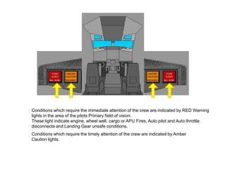
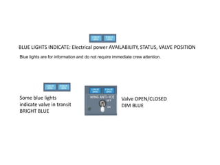
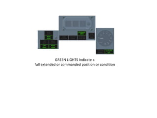
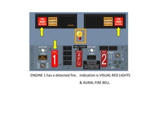
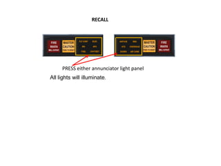
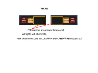
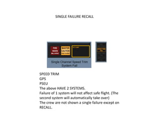
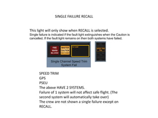
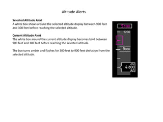
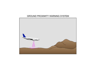
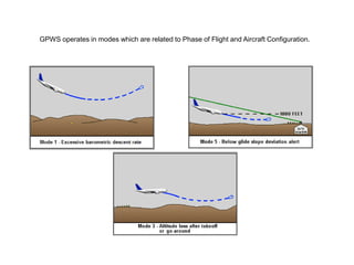
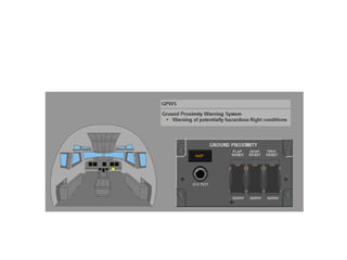
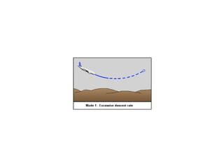
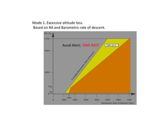
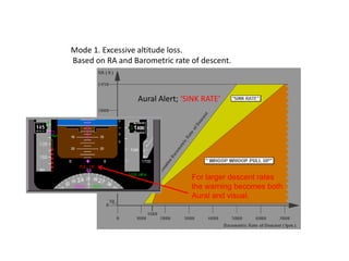
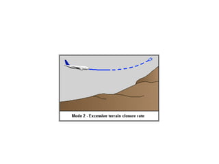
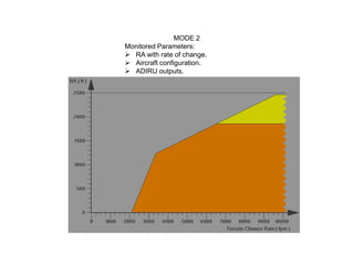
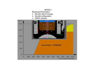
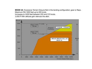
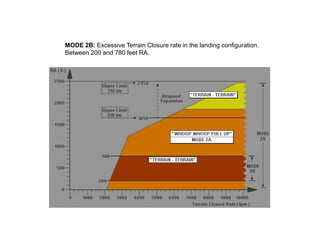
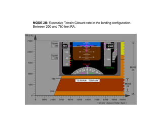
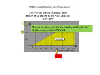
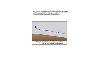
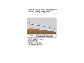
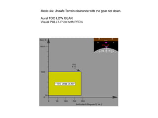
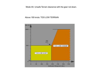
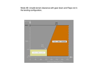
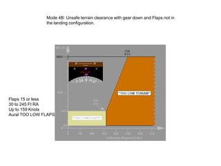
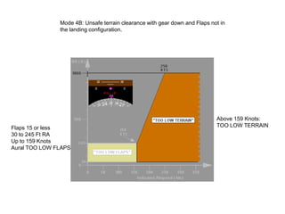
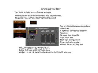
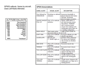
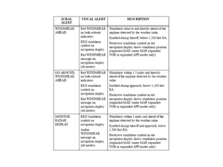
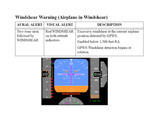
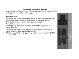
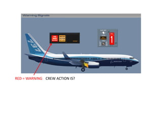
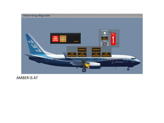
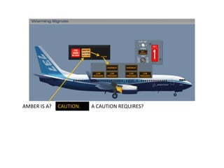
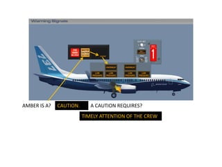
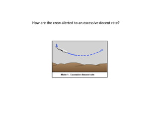
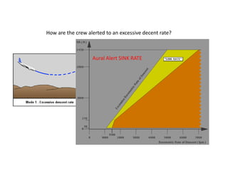
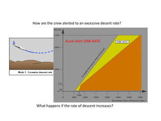
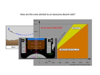
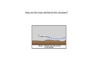
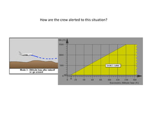
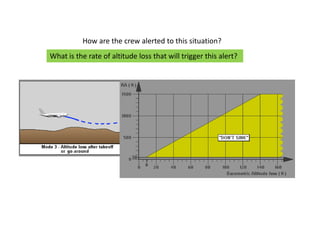
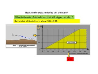
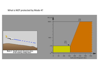
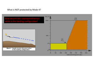
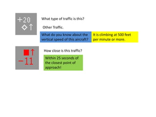
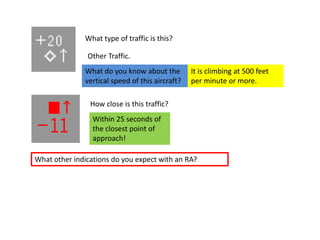
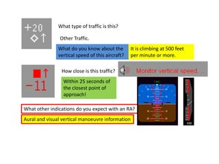
B 737 NG Ground School.
           See the aircraft study guide at www.theorycentre.com

The information contained here is for training purposes only. It is of a general nature it is
unamended and does not relate to any individual aircraft. The FCOM must be consulted for
up to date information on any particular aircraft.
B737-800
WARNING SYSTEMS.
Introduction.
Aural, tactile and visual warning signals alert the flight crew to conditions requiring actions or
caution in the operation of the aircraft. The character of the signal varies depending upon the
degree of urgency or hazards involved. Aural, tactile and visual warnings are used singularly or
in combination to simultaneously provide both warnings and information regarding the nature
of the condition.
STICK SHAKER
Conditions which require the immediate attention of the crew are indicated by RED Warning
lights in the area of the pilots Primary field of vision.
These light indicate engine, wheel well, cargo or APU Fires. Auto pilot and Auto throttle
disconnects and Landing Gear unsafe conditions.
Conditions which require the immediate attention of the crew are indicated by RED Warning
lights in the area of the pilots Primary field of vision.
These light indicate engine, wheel well, cargo or APU Fires. Auto pilot and Auto throttle
disconnects and Landing Gear unsafe conditions.
Conditions which require the timely attention of the crew are indicated by Amber
Caution lights.
BLUE LIGHTS INDICATE: Electrical power AVAILABILITY, STATUS, VALVE POSITION
Blue lights are for information and do not require immediate crew attention.


Some blue lights                                      Valve OPEN/CLOSED
indicate valve in transit                             DIM BLUE
BRIGHT BLUE
GREEN LIGHTS Indicate a
full extended or commanded position or condition
ENGINE 1 has a detected fire. Indication is VISUAL RED LIGHTS
                              & AURAL FIRE BELL
To silence the bell press either of the Fire
Warning lights or Use the Bell cut-out on the
Fire/overheat panel.
To silence the bell press either of the Fire
Warning lights or Use the Bell cut-out on the
Fire/overheat panel.
      The RED light on the Fire/overheat panel will go out
   ONLY WHEN THE FIRE CONDITION IS NO LONGER DETECTED!
Master Caution lights illuminate with an Annunciator light.

The light position on the annunciator panel tells you where to look!
AFT Overhead panel IRS and ENG. PSEU, Equipment cooling.


            FIRE/OVERHEAT PANEL
AFT Overhead panel IRS and ENG. PSEU, Equipment cooling.


            FIRE/OVERHEAT PANEL
A failure has occurred in the Electrical system
Where do you need to look?


               Second row above Captains head.
PRESS either Master Caution light to reset the system.

The FAULT light remains
illuminated until the fault
is corrected.
RECALL


     PRESS either annunciator light panel
All lights will illuminate.
RECALL


         PRESS either annunciator light panel
    All lights will illuminate.
ANY EXISTING FAULTS WILL REMAIN DISPLAYED WHEN RELEASED!
SINGLE FAILURE RECALL


SPEED TRIM
GPS
PSEU
The above HAVE 2 SYSTEMS.
Failure of 1 system will not affect safe flight. (The
second system will automatically take over)
The crew are not shown a single failure except on
RECALL.
SINGLE FAILURE RECALL


This light will only show when RECALL is selected.
Single failure is indicated if the fault light extinguishes when the Caution is
cancelled. If the fault light remains on then both systems have failed.


       SPEED TRIM
       GPS
       PSEU
       The above HAVE 2 SYSTEMS.
       Failure of 1 system will not affect safe flight. (The
       second system will automatically take over)
       The crew are not shown a single failure except on
       RECALL.
Mach/Airspeed Warning System
Two independent Mach/airspeed warning systems provide a distinct aural
warning, a clacker, any time the maximum operating airspeed of Vmo/Mmo is
exceeded. The warning clackers can be silenced only by reducing airspeed below
Vmo/Mmo. Vmo is 340 Knots and Mmo is M 0.82

The airspeed indicator displays red warning bands indicating maximum and
minimum airspeeds. Amber bands indicate maximum and minimum maneuvering
airspeeds. The top of the lower amber band indicates the minimum maneuver
speed. It is the slowest speed that provides full maneuvering: 0.3 g maneuver
margin (40° bank) to stick shaker (below approximately 20,000 ft.) or initial buffet
(above approximately 20,000 ft.).

When either an overspeed condition or a system test occurs, the ADIRU transmits
a signal to the aural warning module, sounding the clacker. The system can only
be tested on the ground.
AFT OVERHEAD PANEL


MACH AIRSPEED WARNING TEST Switches
AFT OVERHEAD PANEL


MACH AIRSPEED WARNING TEST Switches
Push – tests respective mach/airspeed warning system
• clacker sounds
• inhibited air mode.
Stall Warning System
Natural stall warning (buffet) usually occurs at a speed prior to stall. In some
configurations the margin between stall and natural stall warning is less than
desired. Therefore, an artificial stall warning device, a stick shaker, is used to
provide the required warning.
The stall warning “stick shaker” consists of two eccentric weight motors, one on
each control column. They are designed to alert the pilots before a stall develops.
The warning is given by vibrating both control columns. The system is armed in
flight at all times. The system is deactivated on the ground.
Two independent, identical stall management yaw damper (SMYD) computers
determine when stall warning is required based upon:
• alpha vane angle of attack outputs
• ADIRU outputs
• anti–ice controls
• wing configurations
• air/ground sensing
• thrust
• FMC outputs.
The SMYD computers provide outputs for all stall warning to include stick shaker
and signals to the pitch limit indicator and airspeed displays and the GPWS
windshear detection and alert.
Two test switches are installed in the aft overhead panel. Pushing either of these
initiates a self–test of the respective stall warning channel. The No.1 activates the
Captain stick shaker, and the No. 2 activates the F/O stick shaker. Either stick
shaker vibrates both columns through column interconnects.
STALL WARNING TEST Switches
Push – on ground with AC power available: each test switch tests its respective stall
management yaw damper (SMYD) computer. No.1 SMYD computer shakes Captain’s control
column, No.2 SMYD computer shakes First Officer’s control column. Vibrations can be felt on
both columns
• inhibited air mode.
Intermittent Cabin Altitude/Configuration Warning
The takeoff configuration warning is armed when the airplane is on the ground and
either or both forward thrust levers are advanced for takeoff. An intermittent
warning horn sounds if:
• trailing edge flaps are not in the flaps 1 through 25 takeoff range, or
• trailing edge flaps are in a skew or asymmetry condition, or have
uncommanded motion, or
• leading edge devices are not configured for takeoff or have uncommanded
motion, or
• speed brake lever is not in the DOWN position, or
• spoiler control valve is open providing pressurized hydraulic fluid to the
ground spoiler interlock valve, or
• parking brake is set, or
• stabilizer trim not set in the takeoff range.

The Cabin Altitude Warning Horn activates when cabin altitude exceeds 10,000
feet. An intermittent warning horn is heard. The Cabin Altitude Warning Horn
may be silenced by momentarily pressing the ALT HORN CUTOUT switch on the
Cabin Altitude Panel.
WARNING: The Cabin Altitude and Takeoff Configuration Warnings
use the same intermittent tone when activated.
Takeoff Configuration Warning Light (As Installed)
Illuminated (red) –
• activates on the ground as the throttles are advanced if the
airplane is not configured correctly for takeoff
• activation is simultaneous with aural warning intermittent horn for
TAKEOFF CONFIGURATION alert.
Cabin Altitude Warning Light (AS INSTALLED)
Illuminated (red) –
• illuminates at 10,000 feet if the cabin has not been pressurized
• illuminates during flight when loss of cabin pressure occurs
• activation is simultaneous with aural warning intermittent horn
for CABIN ALTITUDE alert.
Altitude Alerts
Selected Altitude Alert
A white box shows around the selected altitude display between 900 feet
and 300 feet before reaching the selected altitude.

Current Altitude Alert
The white box around the current altitude display becomes bold between
900 feet and 300 feet before reaching the selected altitude.

The box turns amber and flashes for 300 feet to 900 feet deviation from the
selected altitude.
GROUND PROXIMITY WARNING SYSTEM
GPWS operates in modes which are related to Phase of Flight and Aircraft Configuration.
GPWS: General.
GPWS is armed between 30 feet RA and 2,450 feet RA
GPWS: General.
GPWS is armed between 30 feet RA and 2,450 feet RA
GPWS has 5 operating modes plus sub modes.
GPWS: General.
GPWS is armed between 30 feet RA and 2,450 feet RA
GPWS has 5 operating modes plus sub modes.
GPWS Monitors various aircraft systems to control the modes
Inoperative (INOP) light
Illuminated (amber) – GPWS computer malfunction or power loss
• invalid inputs are being received from radio altimeter, ADIRU, ILS
receiver, IRS, FMC, stall management computers, or EFIS control panel.
Inoperative (INOP) light
Illuminated (amber) – GPWS computer malfunction or power loss
• invalid inputs are being received from radio altimeter, ADIRU, ILS
receiver, IRS, FMC, stall management computers, or EFIS control panel.

                                             Ground Proximity FLAP INHIBIT Switch
                                             FLAP INHIBIT – inhibits ground proximity TOO LOW FLAPS alert.
                                             NORM (guarded position) – Normal TOO LOW FLAPS alert active.


                                             Ground Proximity GEAR INHIBIT Switch
                                             GEAR INHIBIT – inhibits ground proximity TOO LOW GEAR alert.
                                             NORM (guarded position) – Normal TOO LOW GEAR alert active.

                                             Ground Proximity Terrain Inhibit (TERR INHIBIT) Switch
                                             TERR INHIBIT – inhibits look–ahead terrain alerts and terrain
                                             display.
                                             NORM (guarded position) – Normal terrain alerts and terrain
                                             display active.
Ground Proximity System Test (SYS TEST) Switch
Push –
• momentarily on ground:
• BELOW G/S and GPWS INOP lights illuminate
• TERR FAIL and TERR TEST show on navigation displays
• PULL UP and WINDSHEAR alerts illuminate
• GLIDE SLOPE, PULL UP, and WINDSHEAR aurals sound
• CAUTION TERRAIN aural sounds and TERRAIN caution
message shows on navigation displays.
• until self-test aurals begin, on ground, above indications
always occur first, followed by these additional aurals.
• radio altitude based alerts
• bank angle alert
• approach callouts
• windshear alert
• look ahead terrain alerts
• system test inhibited in-flight.
Mode 1. Excessive altitude loss.
Based on RA and Barometric rate of descent.


                 Aural Alert; ‘SINK RATE’
Mode 1. Excessive altitude loss.
Based on RA and Barometric rate of descent.


                 Aural Alert; ‘SINK RATE’


                                For larger descent rates
                                the warning becomes both
                                Aural and visual.
MODE 2
Monitored Parameters:
 RA with rate of change.
 Aircraft configuration.
 ADIRU outputs.
MODE 2
Monitored Parameters:
 RA with rate of change.
 Aircraft configuration.
 ADIRU outputs.


           Aural Alert; ‘TERRAIN’
MODE 2A: Excessive Terrain Closure Not in the landing configuration, gear or flaps.
Maximum RA 1650 feet up to 220 knots
Increases to 2450 feet between 220 and 310 knots.
3,000 Ft Min altitude gain silences the alert.
MODE 2B: Excessive Terrain Closure rate in the landing configuration.
Between 200 and 780 feet RA.
MODE 2B: Excessive Terrain Closure rate in the landing configuration.
Between 200 and 780 feet RA.
MODE 3: Altitude loss after takeoff or go-around
RA between 30 feet and 1330 Feet.
Aural Don’t Sink
Visual PULL UP on both PFD’s


                  Don’t Sink
MODE 3: Altitude loss after takeoff or go-around
RA between 30 feet and 1330 Feet.
Aural Don’t Sink
Visual PULL UP on both PFD’s


                  Don’t Sink


Transition to MODE 4:
Above 190 knots 1330 Ft RA
Below 190 knots 700 Ft RA.
MODE 3: Altitude loss after takeoff or go-around


   The crew are alerted to descent after
takeoff or Go around by the Aural voice call
                ‘Don’t Sink’
MODE 3: Altitude loss after takeoff or go-around


   The crew are alerted to descent after
takeoff or Go around by the Aural voice call
                ‘Don’t Sink’


      The rate of barometric altitude loss that will trigger this
      alert is approximately 10% of RA.


                                 V.S.I.
MODE 4: Unsafe Terrain clearance when
not in the landing configuration.
MODE 4: Unsafe Terrain clearance when
not in the landing configuration.


Monitored parameters:
Radio Altitude.
Indicated airspeed.
Aircraft configuration.
Mode 4A: Unsafe Terrain clearance with the gear not down.

Aural TOO LOW GEAR
Visual PULL UP on both PFD’s
Mode 4A: Unsafe Terrain clearance with the gear not down.


Above 190 knots: TOO LOW TERRAIN
Mode 4B: Unsafe terrain clearance with gear down and Flaps not in
the landing configuration.
Mode 4B: Unsafe terrain clearance with gear down and Flaps not in
               the landing configuration.


Flaps 15 or less
30 to 245 Ft RA
Up to 159 Knots
Aural TOO LOW FLAPS
Mode 4B: Unsafe terrain clearance with gear down and Flaps not in
               the landing configuration.


                                                                            Above 159 Knots:
Flaps 15 or less                                                            TOO LOW TERRAIN
30 to 245 Ft RA
Up to 159 Knots
Aural TOO LOW FLAPS
Mode 4B: Unsafe terrain clearance with gear down and Flaps not in
               the landing configuration.


                  Mode 4: Simultaneous alerts:
                  TOO LOW GEAR has priority over TOO LOW FLAPS


                                                                            Above 159 Knots:
Flaps 15 or less                                                            TOO LOW TERRAIN
30 to 245 Ft RA
Up to 159 Knots
Aural TOO LOW FLAPS
Mode 4B: Unsafe terrain clearance with gear down and Flaps not in
               the landing configuration.

                  Mode 4: Simultaneous alerts:
                  TOO LOW GEAR has priority over TOO LOW FLAPS


                                                                            Above 159 Knots:
Flaps 15 or less                                                            TOO LOW TERRAIN
30 to 245 Ft RA
Up to 159 Knots
Aural TOO LOW FLAPS


                  MODE 4 Will not protect against slow descent into unprepared
                  terrain while in the landing configuration!
FLAP and GEAR Inhibit switches suppress the
respective Mode 4 sub modes.
MODE 5:
Monitored Parameters.
Radio Altitude.
Glide slope deviation.
MODE 5: Below Glide Slope Deviation Alert.


     Requires.
     Valid signal from Nav 1 G/S Receiver
     RA below 1,000 Ft.


Below Glide slope light illuminates when
alert is active
MODE 5: Below Glide Slope Deviation Alert.
          Requires.
          Valid signal from Nav 1 G/S Receiver
          RA below 1,000 Ft.


   Below Glide slope light illuminates when
   alert is active


Pushing Light
Inhibits alert
Below 1,000 ft RA


Volume and
Repetition rate
Increase as
Deviation
increases
MODE 5: Below Glide Slope Deviation Alert.
          Requires.
          Valid signal from Nav 1 G/S Receiver
          RA below 1,000 Ft.


   Below Glide slope light illuminates when
   alert is active

                                              MODE 5 Simultaneous Alerts.
                                              Mode 1 thru 4 have priority over
Pushing Light                                 Mode 5.
Inhibits alert                                Below Glide slope and PULL UP
Below 1,000 ft RA                             are possible


Volume and
Repetition rate
Increase as
Deviation
increases
Sharply rising terrain ahead of the aircraft cannot be detected by GPWS


Enhanced GPWS Requires Aircraft position, Barometric altitude, vertical
flight path and Ground speed. Terrain within 2,000 Ft of the aircraft
barometric altitude will show on the Terrain display on the ND.
GPWS SYSTEM TEST
Two Tests. In flight is a confidence test only.
On the ground a full vocabulary test may be performed.
Requires: Flaps UP and INOP light extinguished.
GPWS SYSTEM TEST
Two Tests. In flight is a confidence test only.
On the ground a full vocabulary test may be performed.
Requires: Flaps UP and INOP light extinguished.


     PULL UP followed by WINDSHEAR.
     Below G/S light and INOP light show
     AURAL: PULL UP, WINDSHEAR and GLIDESLOPE all sound
GPWS SYSTEM TEST
Two Tests. In flight is a confidence test only.
On the ground a full vocabulary test may be performed.
Requires: Flaps UP and INOP light extinguished.


                                                   Test is Inhibited between takeoff and
                                                   1,000 ft RA.
                                                   In flight is a confidence test only.
                                                   Requires:
                                                   RA more than 1,000 Ft.
                                                   Flaps 15 or less.
                                                   INOP light extinguished.
                                                   Shows indications only
                                                    without the vocabulary test.
     PULL UP followed by WINDSHEAR.
     Below G/S light and INOP light show
     AURAL: PULL UP, WINDSHEAR and GLIDESLOPE all sound
GPWS callouts. Varies by aircraft.
Uses Left Radio Altimeter.
Enhanced Ground Proximity Warning System.
                EGPWS
Enhanced Ground Proximity Warning System. EGPWS
Terrain Display
The actual display varies on software load. More
recent software has a wider coverage range
According to the EGPWS data base used.
ADDITIONAL CALLOUT

                                 Bank angle pointer changes from white to
                                 amber if bank angle is 35º or more


AURAL: BANK ANGLE

First aural at 35º then at 40º
and finally at 45º
Terrain is shown on the ND in Green, Amber and Red.
What is the relative height of terrain displayed in Amber?
Terrain is shown on the ND in Green, Amber and Red.
What is the relative height of terrain displayed in Amber?


      From 500 feet below to 2,000 feet above the aircraft!
Predictive Windshear Display and Annunciations
Windshear Alerts

Windshear alerts are available during takeoff, approach, and landing:

• The GPWS provides a warning when the airplane is in a windshear.

• The weather radar provides alerts for excessive windshear ahead of the airplane.
These are “predictive windshear alerts.”

Windshear warnings are accompanied by WINDSHEAR on the attitude indicators
and voice aural alerts.

Windshear cautions are accompanied by a voice aural alert.

Windshear alerts are prioritized based on the level of hazard and the required flight
crew reaction time.

Predictive windshear alerts are inhibited by an actual windshear warning (airplane
in windshear), look-ahead terrain alerts, or radio altitude based alerts.
Predictive Windshear Alerts
The weather radar uses radar imaging to detect disturbed air prior to entering a windshear.

Note: The weather radar provides windshear alerts for windshear events
containing some level of moisture or particulate matter.

Note: The weather radar detects microbursts and other windshears with similar
characteristics. The weather radar does not provide alerting for all types of
windshear. The flight crew must continue to rely on traditional windshear
avoidance methods.

The weather radar automatically begins scanning for windshear when:
• thrust levers set for takeoff, even if engine is off or IRS not aligned, or
• in flight below 2,300 feet RA (predictive windshear alerts are issued
below 1,200 feet RA).

Alerts are available approximately 12 seconds after the weather radar begins
scanning for windshear. Predictive windshear alerts can be enabled prior to takeoff
by pushing the EFIS control panel WXR switch.
PREDICTIVE WINDSHEAR WARNING DURING TAKEOFF
Predictive Windshear Inhibits
During takeoff and landing, new predictive windshear caution alerts are inhibited
between 80 knots and 400 feet RA, and new warning alerts between 100 knots and 50 feet RA.

These inhibits do not remove existing predictive windshear alerts. If a warning/caution event
occurs before those boundaries, it will remain on the
display and the complete aural callout will be annunciated.
What is the maximum altitude that a windshear
warning is available?
What is the maximum altitude that a windshear
warning is available?


                  1,500 Ft. RA.
On decent the Doppler radar begins to automatically scan for windshear:
a) When below 2,300 feet.
b) At the top of decent.
c) When below 2,500 feet.
d) When below 1,200 feet.
On decent the Doppler radar begins to automatically scan for windshear:
a) When below 2,300 feet. (15.20.15)
b) At the top of decent.
c) When below 2,500 feet.
d) When below 1,200 feet.
On takeoff the Doppler radar will automatically provide windshear detection
to a distance of;
a) 0.5 Nm.
b) 2,300 feet.
c) 1.5 Nm.
d) 3.0 nm.
On takeoff the Doppler radar will automatically provide windshear detection
to a distance of;
a) 0.5 Nm.
b) 2,300 feet.
c) 1.5 Nm.
d) 3.0 nm. (15.20.15)
On takeoff the Doppler radar will automatically provide windshear detection
to a distance of;
a) 0.5 Nm.
b) 2,300 feet.
c) 1.5 Nm.
d) 3.0 nm. (15.20.15)
Landing Gear Configuration Warnings
Visual indications and aural warnings of landing gear position are provided by the
landing gear indicator lights and landing gear warning horn.

Visual Indications
The landing gear indication lights are activated by signals from each gear, the
LANDING GEAR lever, and the forward thrust lever position as follows:
Green light illuminated – landing gear is down and locked.
Red light illuminated –
• landing gear is in disagreement with LANDING GEAR lever position (in
transit or unsafe).
• landing gear is not down and locked (with either or both forward thrust
levers retarded to idle, and below 800 feet AGL).
All lights extinguished – landing gear is up and locked with the LANDING GEAR
lever UP or OFF.
Aural Indications
A steady warning horn is provided to alert the flight crew whenever a landing is
attempted and any gear is not down and locked. The landing gear warning horn is
activated by forward thrust lever and flap position as follows:
Aural Indications
A steady warning horn is provided to alert the flight crew whenever a landing is
attempted and any gear is not down and locked. The landing gear warning horn is
activated by forward thrust lever and flap position as follows:

Flaps up through 10 –
• altitude below 800 feet RA, when either forward thrust lever set between
idle and approximately 20 degrees thrust lever angle or an engine not
operating and the other thrust lever less than 34 degrees. The landing gear
warning horn can be silenced (reset) with the landing gear warning
HORN CUTOUT switch
• if the airplane descends below 200 feet RA, the warning horn cannot be
silenced by the warning HORN CUTOUT switch.
Flaps 15 through 25 –
• either forward thrust lever set below approximately 20 degrees or an
engine not running, and the other thrust lever less than 34 degrees; the
landing gear warning horn cannot be silenced with the landing gear
warning HORN CUTOUT switch.
Flaps greater than 25 –
• regardless of forward thrust lever position; the landing gear warning horn
cannot be silenced with the landing gear warning HORN CUTOUT switch.
The warning indication is cancelled when the configuration error is corrected.
LANDING GEAR CONFIGURATION WARNING


In Flight.
Flaps 25.
Both Thrust levers at idle.


Can the configuration warning horn be silenced?
LANDING GEAR CONFIGURATION WARNING


In Flight.
Flaps 25.
Both Thrust levers at idle.


Can the configuration warning horn be silenced?

  Advance both thrust levers.
  Or lower the gear!
TCAS
                                TCAS interrogates operating transponders
                                in other aircraft.
                                TCAS operation is independent of ground
                                based air traffic control.
  Why can’t
 we see this
 other traffic
  on TCAS?


NO TACAS information is
displayed for any aircraft
which does not have an
operating transponder!
TCAS CONTROLS
TCAS INDICATIONS


    Traffic Advisory (TA)
TCAS INDICATIONS


Resolution Advisory (RA)
      With Aural
TCAS INDICATIONS
                               OTHER TRAFFIC
                                                           Traffic is 2,000 Ft above
                                                           Arrow indicates climbing at
                                                           least 500 ft per Min.


Can be up to 40 miles away and plus or minus 2,700 Feet.
More than 6 miles and more than 1,200 ft vertically
TCAS INDICATIONS
                  PROXIMATE TRAFFIC


                                              Traffic is 1,100 ft above
                                              Climbing at least 500 ft per Min.


Proximate Traffic - Aircraft that is not a TA or RA and is
        within 6 miles and 1200 ft vertically
TCAS INDICATIONS
                              TRAFFIC ADVISORY

                                                            Traffic is 900 ft above
                                                            Climbing at least 500 ft per Min.


Proximate traffic becomes a TA when within 40 Seconds of the closest point of approach.
TCAS INDICATIONS
                     RESOLUTION ADVISORY


TA becomes an RA when within 25 Seconds of the closest point of approach.
TCAS INHIBITS
Below 1,500 ft   INCREASE DESCENT RA’s Inhibited.
Below 1,100 ft   DESCEND RA’s Inhibited.
Below 1,000 ft   ALL RA/TA TCAS voice Inhibited.
RED = WARNING CREW ACTION IS?
RED = WARNING CREW ACTION IS? IMMEDIATE ATTENTION REQUIRED
AMBER IS A?
AMBER IS A?   CAUTION.   A CAUTION REQUIRES?
AMBER IS A?   CAUTION.      A CAUTION REQUIRES?
                         TIMELY ATTENTION OF THE CREW
How are the crew alerted to an excessive decent rate?


                   Aural Alert SINK RATE
How are the crew alerted to an excessive decent rate?


                   Aural Alert SINK RATE


  What happens if the rate of descent increases?
How are the crew alerted to an excessive decent rate?


                   Aural Alert SINK RATE
How are the crew alerted to this situation?
What is the rate of altitude loss that will trigger this alert?
How are the crew alerted to this situation?
What is the rate of altitude loss that will trigger this alert?
Barometric altitude loss is about 10% of RA.


                                                         V.S.I.
What is NOT protected by Mode 4?


Slow decent into unprepared terrain
while in the landing configuration!
TCAS

What is the name given to this traffic?
TCAS

What is the name given to this traffic?

   Proximate Traffic
TCAS

What is the name given to this traffic?

   Proximate Traffic
When does this traffic become a traffic advisory?
TCAS

What is the name given to this traffic?

   Proximate Traffic
When does this traffic become a traffic advisory?


       At 40 seconds from the closest point of approach
What type of traffic is this?

Other Traffic.
What type of traffic is this?

Other Traffic.
What do you know about the
vertical speed of this aircraft?
What type of traffic is this?

Other Traffic.
What do you know about the         It is climbing at 500 feet
vertical speed of this aircraft?   per minute or more.
What type of traffic is this?

Other Traffic.
What do you know about the         It is climbing at 500 feet
vertical speed of this aircraft?   per minute or more.

 How close is this traffic?
What type of traffic is this?

Other Traffic.
What do you know about the         It is climbing at 500 feet
vertical speed of this aircraft?   per minute or more.

 How close is this traffic?
  Within 25 seconds of
  the closest point of
  approach!
What type of traffic is this?

               Other Traffic.
              What do you know about the         It is climbing at 500 feet
              vertical speed of this aircraft?   per minute or more.

                How close is this traffic?
                 Within 25 seconds of
                 the closest point of
                 approach!

What other indications do you expect with an RA?
What type of traffic is this?

               Other Traffic.
               What do you know about the         It is climbing at 500 feet
               vertical speed of this aircraft?   per minute or more.

                How close is this traffic?
                 Within 25 seconds of
                 the closest point of
                 approach!

What other indications do you expect with an RA?
Aural and visual vertical manoeuvre information
In flight the Doppler radar will automatically provide
detected windshear Warnings to a distance of;
In flight the Doppler radar will automatically provide
detected windshear Warnings to a distance of;

1.5 NM. 15.20.15
In flight the Doppler radar will automatically provide
detected windshear Warnings to a distance of;

1.5 NM. 15.20.15

Predictive windshear alerts are shown in which Navigation Display
modes?
In flight the Doppler radar will automatically provide
detected windshear Warnings to a distance of;

1.5 NM. 15.20.15

Predictive windshear alerts are shown in which Navigation Display
modes?

MAP, MAP Centre, Expanded VOR and Expanded APP modes ONLY!
In flight the Doppler radar will automatically provide
detected windshear Warnings to a distance of;

1.5 NM. 15.20.15

Predictive windshear alerts are shown in which Navigation Display
modes?

MAP, MAP Centre, Expanded VOR and Expanded APP modes ONLY!


 A stall warning test may be carried out when?

  ONLY on the GROUND and Requires AC Power!
The END of WARNING SYSTEMS
 Now Take the test at www.theorycentre.com

B 737NG Warning systems.

  • 1.
    B 737 NGGround School. See the aircraft study guide at www.theorycentre.com The information contained here is for training purposes only. It is of a general nature it is unamended and does not relate to any individual aircraft. The FCOM must be consulted for up to date information on any particular aircraft.
  • 2.
  • 3.
    Introduction. Aural, tactile andvisual warning signals alert the flight crew to conditions requiring actions or caution in the operation of the aircraft. The character of the signal varies depending upon the degree of urgency or hazards involved. Aural, tactile and visual warnings are used singularly or in combination to simultaneously provide both warnings and information regarding the nature of the condition.
  • 5.
  • 6.
    Conditions which requirethe immediate attention of the crew are indicated by RED Warning lights in the area of the pilots Primary field of vision. These light indicate engine, wheel well, cargo or APU Fires. Auto pilot and Auto throttle disconnects and Landing Gear unsafe conditions.
  • 7.
    Conditions which requirethe immediate attention of the crew are indicated by RED Warning lights in the area of the pilots Primary field of vision. These light indicate engine, wheel well, cargo or APU Fires. Auto pilot and Auto throttle disconnects and Landing Gear unsafe conditions. Conditions which require the timely attention of the crew are indicated by Amber Caution lights.
  • 8.
    BLUE LIGHTS INDICATE:Electrical power AVAILABILITY, STATUS, VALVE POSITION Blue lights are for information and do not require immediate crew attention. Some blue lights Valve OPEN/CLOSED indicate valve in transit DIM BLUE BRIGHT BLUE
  • 9.
    GREEN LIGHTS Indicatea full extended or commanded position or condition
  • 10.
    ENGINE 1 hasa detected fire. Indication is VISUAL RED LIGHTS & AURAL FIRE BELL
  • 11.
    To silence thebell press either of the Fire Warning lights or Use the Bell cut-out on the Fire/overheat panel.
  • 12.
    To silence thebell press either of the Fire Warning lights or Use the Bell cut-out on the Fire/overheat panel. The RED light on the Fire/overheat panel will go out ONLY WHEN THE FIRE CONDITION IS NO LONGER DETECTED!
  • 13.
    Master Caution lightsilluminate with an Annunciator light. The light position on the annunciator panel tells you where to look!
  • 14.
    AFT Overhead panelIRS and ENG. PSEU, Equipment cooling. FIRE/OVERHEAT PANEL
  • 15.
    AFT Overhead panelIRS and ENG. PSEU, Equipment cooling. FIRE/OVERHEAT PANEL
  • 16.
    A failure hasoccurred in the Electrical system Where do you need to look? Second row above Captains head.
  • 17.
    PRESS either MasterCaution light to reset the system.
  • 18.
    PRESS either MasterCaution light to reset the system. The FAULT light remains illuminated until the fault is corrected.
  • 19.
    RECALL PRESS either annunciator light panel All lights will illuminate.
  • 20.
    RECALL PRESS either annunciator light panel All lights will illuminate. ANY EXISTING FAULTS WILL REMAIN DISPLAYED WHEN RELEASED!
  • 21.
    SINGLE FAILURE RECALL SPEEDTRIM GPS PSEU The above HAVE 2 SYSTEMS. Failure of 1 system will not affect safe flight. (The second system will automatically take over) The crew are not shown a single failure except on RECALL.
  • 22.
    SINGLE FAILURE RECALL Thislight will only show when RECALL is selected. Single failure is indicated if the fault light extinguishes when the Caution is cancelled. If the fault light remains on then both systems have failed. SPEED TRIM GPS PSEU The above HAVE 2 SYSTEMS. Failure of 1 system will not affect safe flight. (The second system will automatically take over) The crew are not shown a single failure except on RECALL.
  • 23.
    Mach/Airspeed Warning System Twoindependent Mach/airspeed warning systems provide a distinct aural warning, a clacker, any time the maximum operating airspeed of Vmo/Mmo is exceeded. The warning clackers can be silenced only by reducing airspeed below Vmo/Mmo. Vmo is 340 Knots and Mmo is M 0.82 The airspeed indicator displays red warning bands indicating maximum and minimum airspeeds. Amber bands indicate maximum and minimum maneuvering airspeeds. The top of the lower amber band indicates the minimum maneuver speed. It is the slowest speed that provides full maneuvering: 0.3 g maneuver margin (40° bank) to stick shaker (below approximately 20,000 ft.) or initial buffet (above approximately 20,000 ft.). When either an overspeed condition or a system test occurs, the ADIRU transmits a signal to the aural warning module, sounding the clacker. The system can only be tested on the ground.
  • 24.
    AFT OVERHEAD PANEL MACHAIRSPEED WARNING TEST Switches
  • 25.
    AFT OVERHEAD PANEL MACHAIRSPEED WARNING TEST Switches Push – tests respective mach/airspeed warning system • clacker sounds • inhibited air mode.
  • 26.
    Stall Warning System Naturalstall warning (buffet) usually occurs at a speed prior to stall. In some configurations the margin between stall and natural stall warning is less than desired. Therefore, an artificial stall warning device, a stick shaker, is used to provide the required warning. The stall warning “stick shaker” consists of two eccentric weight motors, one on each control column. They are designed to alert the pilots before a stall develops. The warning is given by vibrating both control columns. The system is armed in flight at all times. The system is deactivated on the ground. Two independent, identical stall management yaw damper (SMYD) computers determine when stall warning is required based upon: • alpha vane angle of attack outputs • ADIRU outputs • anti–ice controls • wing configurations • air/ground sensing • thrust • FMC outputs. The SMYD computers provide outputs for all stall warning to include stick shaker and signals to the pitch limit indicator and airspeed displays and the GPWS windshear detection and alert. Two test switches are installed in the aft overhead panel. Pushing either of these initiates a self–test of the respective stall warning channel. The No.1 activates the Captain stick shaker, and the No. 2 activates the F/O stick shaker. Either stick shaker vibrates both columns through column interconnects.
  • 27.
  • 28.
    STALL WARNING TESTSwitches Push – on ground with AC power available: each test switch tests its respective stall management yaw damper (SMYD) computer. No.1 SMYD computer shakes Captain’s control column, No.2 SMYD computer shakes First Officer’s control column. Vibrations can be felt on both columns • inhibited air mode.
  • 29.
    Intermittent Cabin Altitude/ConfigurationWarning The takeoff configuration warning is armed when the airplane is on the ground and either or both forward thrust levers are advanced for takeoff. An intermittent warning horn sounds if: • trailing edge flaps are not in the flaps 1 through 25 takeoff range, or • trailing edge flaps are in a skew or asymmetry condition, or have uncommanded motion, or • leading edge devices are not configured for takeoff or have uncommanded motion, or • speed brake lever is not in the DOWN position, or • spoiler control valve is open providing pressurized hydraulic fluid to the ground spoiler interlock valve, or • parking brake is set, or • stabilizer trim not set in the takeoff range. The Cabin Altitude Warning Horn activates when cabin altitude exceeds 10,000 feet. An intermittent warning horn is heard. The Cabin Altitude Warning Horn may be silenced by momentarily pressing the ALT HORN CUTOUT switch on the Cabin Altitude Panel. WARNING: The Cabin Altitude and Takeoff Configuration Warnings use the same intermittent tone when activated.
  • 30.
    Takeoff Configuration WarningLight (As Installed) Illuminated (red) – • activates on the ground as the throttles are advanced if the airplane is not configured correctly for takeoff • activation is simultaneous with aural warning intermittent horn for TAKEOFF CONFIGURATION alert.
  • 31.
    Cabin Altitude WarningLight (AS INSTALLED) Illuminated (red) – • illuminates at 10,000 feet if the cabin has not been pressurized • illuminates during flight when loss of cabin pressure occurs • activation is simultaneous with aural warning intermittent horn for CABIN ALTITUDE alert.
  • 32.
    Altitude Alerts Selected AltitudeAlert A white box shows around the selected altitude display between 900 feet and 300 feet before reaching the selected altitude. Current Altitude Alert The white box around the current altitude display becomes bold between 900 feet and 300 feet before reaching the selected altitude. The box turns amber and flashes for 300 feet to 900 feet deviation from the selected altitude.
  • 33.
  • 34.
    GPWS operates inmodes which are related to Phase of Flight and Aircraft Configuration.
  • 36.
    GPWS: General. GPWS isarmed between 30 feet RA and 2,450 feet RA
  • 37.
    GPWS: General. GPWS isarmed between 30 feet RA and 2,450 feet RA GPWS has 5 operating modes plus sub modes.
  • 38.
    GPWS: General. GPWS isarmed between 30 feet RA and 2,450 feet RA GPWS has 5 operating modes plus sub modes. GPWS Monitors various aircraft systems to control the modes
  • 39.
    Inoperative (INOP) light Illuminated(amber) – GPWS computer malfunction or power loss • invalid inputs are being received from radio altimeter, ADIRU, ILS receiver, IRS, FMC, stall management computers, or EFIS control panel.
  • 40.
    Inoperative (INOP) light Illuminated(amber) – GPWS computer malfunction or power loss • invalid inputs are being received from radio altimeter, ADIRU, ILS receiver, IRS, FMC, stall management computers, or EFIS control panel. Ground Proximity FLAP INHIBIT Switch FLAP INHIBIT – inhibits ground proximity TOO LOW FLAPS alert. NORM (guarded position) – Normal TOO LOW FLAPS alert active.
  • 41.
    Inoperative (INOP) light Illuminated(amber) – GPWS computer malfunction or power loss • invalid inputs are being received from radio altimeter, ADIRU, ILS receiver, IRS, FMC, stall management computers, or EFIS control panel. Ground Proximity FLAP INHIBIT Switch FLAP INHIBIT – inhibits ground proximity TOO LOW FLAPS alert. NORM (guarded position) – Normal TOO LOW FLAPS alert active. Ground Proximity GEAR INHIBIT Switch GEAR INHIBIT – inhibits ground proximity TOO LOW GEAR alert. NORM (guarded position) – Normal TOO LOW GEAR alert active.
  • 42.
    Inoperative (INOP) light Illuminated(amber) – GPWS computer malfunction or power loss • invalid inputs are being received from radio altimeter, ADIRU, ILS receiver, IRS, FMC, stall management computers, or EFIS control panel. Ground Proximity FLAP INHIBIT Switch FLAP INHIBIT – inhibits ground proximity TOO LOW FLAPS alert. NORM (guarded position) – Normal TOO LOW FLAPS alert active. Ground Proximity GEAR INHIBIT Switch GEAR INHIBIT – inhibits ground proximity TOO LOW GEAR alert. NORM (guarded position) – Normal TOO LOW GEAR alert active. Ground Proximity Terrain Inhibit (TERR INHIBIT) Switch TERR INHIBIT – inhibits look–ahead terrain alerts and terrain display. NORM (guarded position) – Normal terrain alerts and terrain display active.
  • 43.
    Ground Proximity SystemTest (SYS TEST) Switch Push – • momentarily on ground: • BELOW G/S and GPWS INOP lights illuminate • TERR FAIL and TERR TEST show on navigation displays • PULL UP and WINDSHEAR alerts illuminate • GLIDE SLOPE, PULL UP, and WINDSHEAR aurals sound • CAUTION TERRAIN aural sounds and TERRAIN caution message shows on navigation displays. • until self-test aurals begin, on ground, above indications always occur first, followed by these additional aurals. • radio altitude based alerts • bank angle alert • approach callouts • windshear alert • look ahead terrain alerts • system test inhibited in-flight.
  • 45.
    Mode 1. Excessivealtitude loss. Based on RA and Barometric rate of descent. Aural Alert; ‘SINK RATE’
  • 46.
    Mode 1. Excessivealtitude loss. Based on RA and Barometric rate of descent. Aural Alert; ‘SINK RATE’ For larger descent rates the warning becomes both Aural and visual.
  • 48.
    MODE 2 Monitored Parameters: RA with rate of change.  Aircraft configuration.  ADIRU outputs.
  • 49.
    MODE 2 Monitored Parameters: RA with rate of change.  Aircraft configuration.  ADIRU outputs. Aural Alert; ‘TERRAIN’
  • 50.
    MODE 2A: ExcessiveTerrain Closure Not in the landing configuration, gear or flaps. Maximum RA 1650 feet up to 220 knots Increases to 2450 feet between 220 and 310 knots. 3,000 Ft Min altitude gain silences the alert.
  • 51.
    MODE 2B: ExcessiveTerrain Closure rate in the landing configuration. Between 200 and 780 feet RA.
  • 52.
    MODE 2B: ExcessiveTerrain Closure rate in the landing configuration. Between 200 and 780 feet RA.
  • 53.
    MODE 3: Altitudeloss after takeoff or go-around
  • 54.
    MODE 3: Altitudeloss after takeoff or go-around RA between 30 feet and 1330 Feet. Aural Don’t Sink Visual PULL UP on both PFD’s Don’t Sink
  • 55.
    MODE 3: Altitudeloss after takeoff or go-around RA between 30 feet and 1330 Feet. Aural Don’t Sink Visual PULL UP on both PFD’s Don’t Sink Transition to MODE 4: Above 190 knots 1330 Ft RA Below 190 knots 700 Ft RA.
  • 56.
    MODE 3: Altitudeloss after takeoff or go-around The crew are alerted to descent after takeoff or Go around by the Aural voice call ‘Don’t Sink’
  • 57.
    MODE 3: Altitudeloss after takeoff or go-around The crew are alerted to descent after takeoff or Go around by the Aural voice call ‘Don’t Sink’ The rate of barometric altitude loss that will trigger this alert is approximately 10% of RA. V.S.I.
  • 58.
    MODE 4: UnsafeTerrain clearance when not in the landing configuration.
  • 59.
    MODE 4: UnsafeTerrain clearance when not in the landing configuration. Monitored parameters: Radio Altitude. Indicated airspeed. Aircraft configuration.
  • 60.
    Mode 4A: UnsafeTerrain clearance with the gear not down. Aural TOO LOW GEAR Visual PULL UP on both PFD’s
  • 61.
    Mode 4A: UnsafeTerrain clearance with the gear not down. Above 190 knots: TOO LOW TERRAIN
  • 62.
    Mode 4B: Unsafeterrain clearance with gear down and Flaps not in the landing configuration.
  • 63.
    Mode 4B: Unsafeterrain clearance with gear down and Flaps not in the landing configuration. Flaps 15 or less 30 to 245 Ft RA Up to 159 Knots Aural TOO LOW FLAPS
  • 64.
    Mode 4B: Unsafeterrain clearance with gear down and Flaps not in the landing configuration. Above 159 Knots: Flaps 15 or less TOO LOW TERRAIN 30 to 245 Ft RA Up to 159 Knots Aural TOO LOW FLAPS
  • 65.
    Mode 4B: Unsafeterrain clearance with gear down and Flaps not in the landing configuration. Mode 4: Simultaneous alerts: TOO LOW GEAR has priority over TOO LOW FLAPS Above 159 Knots: Flaps 15 or less TOO LOW TERRAIN 30 to 245 Ft RA Up to 159 Knots Aural TOO LOW FLAPS
  • 66.
    Mode 4B: Unsafeterrain clearance with gear down and Flaps not in the landing configuration. Mode 4: Simultaneous alerts: TOO LOW GEAR has priority over TOO LOW FLAPS Above 159 Knots: Flaps 15 or less TOO LOW TERRAIN 30 to 245 Ft RA Up to 159 Knots Aural TOO LOW FLAPS MODE 4 Will not protect against slow descent into unprepared terrain while in the landing configuration!
  • 67.
    FLAP and GEARInhibit switches suppress the respective Mode 4 sub modes.
  • 68.
    MODE 5: Monitored Parameters. RadioAltitude. Glide slope deviation.
  • 70.
    MODE 5: BelowGlide Slope Deviation Alert. Requires. Valid signal from Nav 1 G/S Receiver RA below 1,000 Ft. Below Glide slope light illuminates when alert is active
  • 71.
    MODE 5: BelowGlide Slope Deviation Alert. Requires. Valid signal from Nav 1 G/S Receiver RA below 1,000 Ft. Below Glide slope light illuminates when alert is active Pushing Light Inhibits alert Below 1,000 ft RA Volume and Repetition rate Increase as Deviation increases
  • 72.
    MODE 5: BelowGlide Slope Deviation Alert. Requires. Valid signal from Nav 1 G/S Receiver RA below 1,000 Ft. Below Glide slope light illuminates when alert is active MODE 5 Simultaneous Alerts. Mode 1 thru 4 have priority over Pushing Light Mode 5. Inhibits alert Below Glide slope and PULL UP Below 1,000 ft RA are possible Volume and Repetition rate Increase as Deviation increases
  • 73.
    Sharply rising terrainahead of the aircraft cannot be detected by GPWS
  • 74.
    Sharply rising terrainahead of the aircraft cannot be detected by GPWS Enhanced GPWS Requires Aircraft position, Barometric altitude, vertical flight path and Ground speed. Terrain within 2,000 Ft of the aircraft barometric altitude will show on the Terrain display on the ND.
  • 75.
    GPWS SYSTEM TEST TwoTests. In flight is a confidence test only. On the ground a full vocabulary test may be performed. Requires: Flaps UP and INOP light extinguished.
  • 76.
    GPWS SYSTEM TEST TwoTests. In flight is a confidence test only. On the ground a full vocabulary test may be performed. Requires: Flaps UP and INOP light extinguished. PULL UP followed by WINDSHEAR. Below G/S light and INOP light show AURAL: PULL UP, WINDSHEAR and GLIDESLOPE all sound
  • 77.
    GPWS SYSTEM TEST TwoTests. In flight is a confidence test only. On the ground a full vocabulary test may be performed. Requires: Flaps UP and INOP light extinguished. Test is Inhibited between takeoff and 1,000 ft RA. In flight is a confidence test only. Requires: RA more than 1,000 Ft. Flaps 15 or less. INOP light extinguished. Shows indications only without the vocabulary test. PULL UP followed by WINDSHEAR. Below G/S light and INOP light show AURAL: PULL UP, WINDSHEAR and GLIDESLOPE all sound
  • 78.
    GPWS callouts. Variesby aircraft. Uses Left Radio Altimeter.
  • 79.
    Enhanced Ground ProximityWarning System. EGPWS
  • 80.
    Enhanced Ground ProximityWarning System. EGPWS
  • 81.
    Terrain Display The actualdisplay varies on software load. More recent software has a wider coverage range
  • 86.
    According to theEGPWS data base used.
  • 87.
    ADDITIONAL CALLOUT Bank angle pointer changes from white to amber if bank angle is 35º or more AURAL: BANK ANGLE First aural at 35º then at 40º and finally at 45º
  • 88.
    Terrain is shownon the ND in Green, Amber and Red. What is the relative height of terrain displayed in Amber?
  • 89.
    Terrain is shownon the ND in Green, Amber and Red. What is the relative height of terrain displayed in Amber? From 500 feet below to 2,000 feet above the aircraft!
  • 90.
  • 91.
    Windshear Alerts Windshear alertsare available during takeoff, approach, and landing: • The GPWS provides a warning when the airplane is in a windshear. • The weather radar provides alerts for excessive windshear ahead of the airplane. These are “predictive windshear alerts.” Windshear warnings are accompanied by WINDSHEAR on the attitude indicators and voice aural alerts. Windshear cautions are accompanied by a voice aural alert. Windshear alerts are prioritized based on the level of hazard and the required flight crew reaction time. Predictive windshear alerts are inhibited by an actual windshear warning (airplane in windshear), look-ahead terrain alerts, or radio altitude based alerts.
  • 92.
    Predictive Windshear Alerts Theweather radar uses radar imaging to detect disturbed air prior to entering a windshear. Note: The weather radar provides windshear alerts for windshear events containing some level of moisture or particulate matter. Note: The weather radar detects microbursts and other windshears with similar characteristics. The weather radar does not provide alerting for all types of windshear. The flight crew must continue to rely on traditional windshear avoidance methods. The weather radar automatically begins scanning for windshear when: • thrust levers set for takeoff, even if engine is off or IRS not aligned, or • in flight below 2,300 feet RA (predictive windshear alerts are issued below 1,200 feet RA). Alerts are available approximately 12 seconds after the weather radar begins scanning for windshear. Predictive windshear alerts can be enabled prior to takeoff by pushing the EFIS control panel WXR switch.
  • 93.
  • 94.
    Predictive Windshear Inhibits Duringtakeoff and landing, new predictive windshear caution alerts are inhibited between 80 knots and 400 feet RA, and new warning alerts between 100 knots and 50 feet RA. These inhibits do not remove existing predictive windshear alerts. If a warning/caution event occurs before those boundaries, it will remain on the display and the complete aural callout will be annunciated.
  • 98.
    What is themaximum altitude that a windshear warning is available?
  • 99.
    What is themaximum altitude that a windshear warning is available? 1,500 Ft. RA.
  • 100.
    On decent theDoppler radar begins to automatically scan for windshear: a) When below 2,300 feet. b) At the top of decent. c) When below 2,500 feet. d) When below 1,200 feet.
  • 101.
    On decent theDoppler radar begins to automatically scan for windshear: a) When below 2,300 feet. (15.20.15) b) At the top of decent. c) When below 2,500 feet. d) When below 1,200 feet.
  • 102.
    On takeoff theDoppler radar will automatically provide windshear detection to a distance of; a) 0.5 Nm. b) 2,300 feet. c) 1.5 Nm. d) 3.0 nm.
  • 103.
    On takeoff theDoppler radar will automatically provide windshear detection to a distance of; a) 0.5 Nm. b) 2,300 feet. c) 1.5 Nm. d) 3.0 nm. (15.20.15)
  • 104.
    On takeoff theDoppler radar will automatically provide windshear detection to a distance of; a) 0.5 Nm. b) 2,300 feet. c) 1.5 Nm. d) 3.0 nm. (15.20.15)
  • 106.
    Landing Gear ConfigurationWarnings Visual indications and aural warnings of landing gear position are provided by the landing gear indicator lights and landing gear warning horn. Visual Indications The landing gear indication lights are activated by signals from each gear, the LANDING GEAR lever, and the forward thrust lever position as follows: Green light illuminated – landing gear is down and locked. Red light illuminated – • landing gear is in disagreement with LANDING GEAR lever position (in transit or unsafe). • landing gear is not down and locked (with either or both forward thrust levers retarded to idle, and below 800 feet AGL). All lights extinguished – landing gear is up and locked with the LANDING GEAR lever UP or OFF.
  • 107.
    Aural Indications A steadywarning horn is provided to alert the flight crew whenever a landing is attempted and any gear is not down and locked. The landing gear warning horn is activated by forward thrust lever and flap position as follows:
  • 108.
    Aural Indications A steadywarning horn is provided to alert the flight crew whenever a landing is attempted and any gear is not down and locked. The landing gear warning horn is activated by forward thrust lever and flap position as follows: Flaps up through 10 – • altitude below 800 feet RA, when either forward thrust lever set between idle and approximately 20 degrees thrust lever angle or an engine not operating and the other thrust lever less than 34 degrees. The landing gear warning horn can be silenced (reset) with the landing gear warning HORN CUTOUT switch • if the airplane descends below 200 feet RA, the warning horn cannot be silenced by the warning HORN CUTOUT switch.
  • 109.
    Aural Indications A steadywarning horn is provided to alert the flight crew whenever a landing is attempted and any gear is not down and locked. The landing gear warning horn is activated by forward thrust lever and flap position as follows: Flaps up through 10 – • altitude below 800 feet RA, when either forward thrust lever set between idle and approximately 20 degrees thrust lever angle or an engine not operating and the other thrust lever less than 34 degrees. The landing gear warning horn can be silenced (reset) with the landing gear warning HORN CUTOUT switch • if the airplane descends below 200 feet RA, the warning horn cannot be silenced by the warning HORN CUTOUT switch. Flaps 15 through 25 – • either forward thrust lever set below approximately 20 degrees or an engine not running, and the other thrust lever less than 34 degrees; the landing gear warning horn cannot be silenced with the landing gear warning HORN CUTOUT switch.
  • 110.
    Aural Indications A steadywarning horn is provided to alert the flight crew whenever a landing is attempted and any gear is not down and locked. The landing gear warning horn is activated by forward thrust lever and flap position as follows: Flaps up through 10 – • altitude below 800 feet RA, when either forward thrust lever set between idle and approximately 20 degrees thrust lever angle or an engine not operating and the other thrust lever less than 34 degrees. The landing gear warning horn can be silenced (reset) with the landing gear warning HORN CUTOUT switch • if the airplane descends below 200 feet RA, the warning horn cannot be silenced by the warning HORN CUTOUT switch. Flaps 15 through 25 – • either forward thrust lever set below approximately 20 degrees or an engine not running, and the other thrust lever less than 34 degrees; the landing gear warning horn cannot be silenced with the landing gear warning HORN CUTOUT switch. Flaps greater than 25 – • regardless of forward thrust lever position; the landing gear warning horn cannot be silenced with the landing gear warning HORN CUTOUT switch. The warning indication is cancelled when the configuration error is corrected.
  • 111.
    LANDING GEAR CONFIGURATIONWARNING In Flight. Flaps 25. Both Thrust levers at idle. Can the configuration warning horn be silenced?
  • 112.
    LANDING GEAR CONFIGURATIONWARNING In Flight. Flaps 25. Both Thrust levers at idle. Can the configuration warning horn be silenced? Advance both thrust levers. Or lower the gear!
  • 113.
    TCAS TCAS interrogates operating transponders in other aircraft. TCAS operation is independent of ground based air traffic control. Why can’t we see this other traffic on TCAS? NO TACAS information is displayed for any aircraft which does not have an operating transponder!
  • 114.
  • 115.
    TCAS INDICATIONS Traffic Advisory (TA)
  • 116.
  • 118.
    TCAS INDICATIONS OTHER TRAFFIC Traffic is 2,000 Ft above Arrow indicates climbing at least 500 ft per Min. Can be up to 40 miles away and plus or minus 2,700 Feet. More than 6 miles and more than 1,200 ft vertically
  • 119.
    TCAS INDICATIONS PROXIMATE TRAFFIC Traffic is 1,100 ft above Climbing at least 500 ft per Min. Proximate Traffic - Aircraft that is not a TA or RA and is within 6 miles and 1200 ft vertically
  • 120.
    TCAS INDICATIONS TRAFFIC ADVISORY Traffic is 900 ft above Climbing at least 500 ft per Min. Proximate traffic becomes a TA when within 40 Seconds of the closest point of approach.
  • 121.
    TCAS INDICATIONS RESOLUTION ADVISORY TA becomes an RA when within 25 Seconds of the closest point of approach.
  • 122.
    TCAS INHIBITS Below 1,500ft INCREASE DESCENT RA’s Inhibited. Below 1,100 ft DESCEND RA’s Inhibited. Below 1,000 ft ALL RA/TA TCAS voice Inhibited.
  • 123.
    RED = WARNINGCREW ACTION IS?
  • 124.
    RED = WARNINGCREW ACTION IS? IMMEDIATE ATTENTION REQUIRED
  • 125.
  • 126.
    AMBER IS A? CAUTION. A CAUTION REQUIRES?
  • 127.
    AMBER IS A? CAUTION. A CAUTION REQUIRES? TIMELY ATTENTION OF THE CREW
  • 128.
    How are thecrew alerted to an excessive decent rate?
  • 129.
    How are thecrew alerted to an excessive decent rate? Aural Alert SINK RATE
  • 130.
    How are thecrew alerted to an excessive decent rate? Aural Alert SINK RATE What happens if the rate of descent increases?
  • 131.
    How are thecrew alerted to an excessive decent rate? Aural Alert SINK RATE
  • 132.
    How are thecrew alerted to this situation?
  • 133.
    How are thecrew alerted to this situation?
  • 134.
    How are thecrew alerted to this situation? What is the rate of altitude loss that will trigger this alert?
  • 135.
    How are thecrew alerted to this situation? What is the rate of altitude loss that will trigger this alert? Barometric altitude loss is about 10% of RA. V.S.I.
  • 136.
    What is NOTprotected by Mode 4?
  • 137.
    What is NOTprotected by Mode 4? Slow decent into unprepared terrain while in the landing configuration!
  • 138.
    TCAS What is thename given to this traffic?
  • 139.
    TCAS What is thename given to this traffic? Proximate Traffic
  • 140.
    TCAS What is thename given to this traffic? Proximate Traffic When does this traffic become a traffic advisory?
  • 141.
    TCAS What is thename given to this traffic? Proximate Traffic When does this traffic become a traffic advisory? At 40 seconds from the closest point of approach
  • 142.
    What type oftraffic is this?
  • 143.
    What type oftraffic is this? Other Traffic.
  • 144.
    What type oftraffic is this? Other Traffic. What do you know about the vertical speed of this aircraft?
  • 145.
    What type oftraffic is this? Other Traffic. What do you know about the It is climbing at 500 feet vertical speed of this aircraft? per minute or more.
  • 146.
    What type oftraffic is this? Other Traffic. What do you know about the It is climbing at 500 feet vertical speed of this aircraft? per minute or more. How close is this traffic?
  • 147.
    What type oftraffic is this? Other Traffic. What do you know about the It is climbing at 500 feet vertical speed of this aircraft? per minute or more. How close is this traffic? Within 25 seconds of the closest point of approach!
  • 148.
    What type oftraffic is this? Other Traffic. What do you know about the It is climbing at 500 feet vertical speed of this aircraft? per minute or more. How close is this traffic? Within 25 seconds of the closest point of approach! What other indications do you expect with an RA?
  • 149.
    What type oftraffic is this? Other Traffic. What do you know about the It is climbing at 500 feet vertical speed of this aircraft? per minute or more. How close is this traffic? Within 25 seconds of the closest point of approach! What other indications do you expect with an RA? Aural and visual vertical manoeuvre information
  • 150.
    In flight theDoppler radar will automatically provide detected windshear Warnings to a distance of;
  • 151.
    In flight theDoppler radar will automatically provide detected windshear Warnings to a distance of; 1.5 NM. 15.20.15
  • 152.
    In flight theDoppler radar will automatically provide detected windshear Warnings to a distance of; 1.5 NM. 15.20.15 Predictive windshear alerts are shown in which Navigation Display modes?
  • 153.
    In flight theDoppler radar will automatically provide detected windshear Warnings to a distance of; 1.5 NM. 15.20.15 Predictive windshear alerts are shown in which Navigation Display modes? MAP, MAP Centre, Expanded VOR and Expanded APP modes ONLY!
  • 154.
    In flight theDoppler radar will automatically provide detected windshear Warnings to a distance of; 1.5 NM. 15.20.15 Predictive windshear alerts are shown in which Navigation Display modes? MAP, MAP Centre, Expanded VOR and Expanded APP modes ONLY! A stall warning test may be carried out when?
  • 155.
    In flight theDoppler radar will automatically provide detected windshear Warnings to a distance of; 1.5 NM. 15.20.15 Predictive windshear alerts are shown in which Navigation Display modes? MAP, MAP Centre, Expanded VOR and Expanded APP modes ONLY! A stall warning test may be carried out when? ONLY on the GROUND and Requires AC Power!
  • 156.
    The END ofWARNING SYSTEMS Now Take the test at www.theorycentre.com