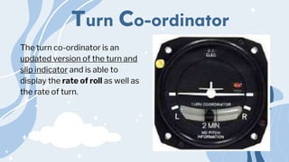
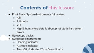
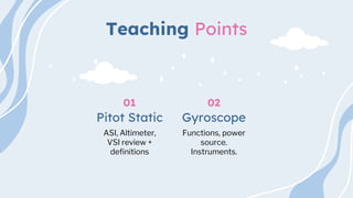
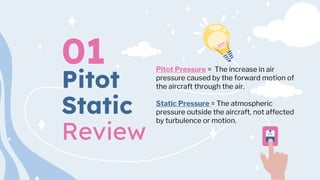
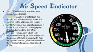
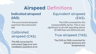
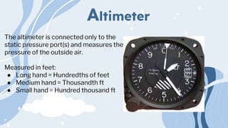
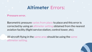
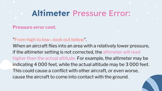
a slideshow about the pitot static and gyroscopic instruments. this slideshow has review slides as well as stuff about the asi like the errors and other important things like that. I hope you find this
4. Pitot
Static
Review
01 Pitot Pressure = The increase in air
pressure caused by the forward motion of
the aircraft through the air.
Static Pressure = The atmospheric
pressure outside the aircraft, not affected
by turbulence or motion.
5. Air Speed Iindicator
● Red. A red line indicates the never
exceed speed (VNE).
● Yellow. A yellow arc starts at the
maximum structural cruise (VNO) and
extends to the VNE. caution range.
● Green. The normal operating range. It
starts at the power-off stalling speed
(VSL) and extends to the VNO.
● White. The range in which fully
extended flaps may be used. It starts at
the power-off stalling speed with flaps
and gear extended (VSO) and extends to
the maximum flaps extended speed
(VFE).
6. ASI Errors:
Density error.
The ASI is calibrated for normal sea level pressure of 29.92
inches of mercury (Hg) at a temperature of 15 degrees
Celsius.
Temperature and pressure normally decrease with an
increase in altitude, decreasing the density of the air and
causing the ASI to read less than the true airspeed.
7. ASI Errors:
Position error.
Results from the position of the pitot pressure source.
Eddies formed by air moving over the aircraft and the angle of the
pitot source to the airflow cause position error.
8. ASI Errors:
Lag error.
A mechanical error that is the result of friction between the
working parts of the instrument.
This error is responsible for a slight delay between a change in
airspeed occurring and the change being shown on the
instrument.
9. ASI Errors:
Icing error.
The error caused by a complete or partial blockage of the pitot
pressure by ice.
This error can be prevented or corrected by turning on the pitot
heat (if equipped) or descending to a lower altitude where the
outside air temperature (OAT) is higher.
10. ASI Errors:
Water error.
Water in the system can cause higher or lower than normal
readings and may block the system completely.
Water can be kept out of the system by covering the pitot source
when the aircraft is parked. This will also keep dirt and insects
from entering the system.
11. Airspeed Definitions
The IAS corrected for
instrument (lag) error and
installation (position) error
The uncorrected airspeed
read from the instrument
dial.
The CAS corrected for the
compressibility factor. This is very
significant to aircraft operating above
10 000 feet and 250 knots (kt).
Equivalent airspeed
(EAS).
Indicated airspeed
(IAS).
Calibrated
airspeed (CAS).
The CAS (or EAS) corrected for
density (pressure and
temperature).
True airspeed (TAS).
12. Altimeter
The altimeter is connected only to the
static pressure port(s) and measures the
pressure of the outside air.
Measured in feet:
● Long hand = Hundredths of feet
● Medium hand = Thousandth ft
● Small hand = Hundred thousand ft
13. Altimeter Errors:
Pressure error.
Barometric pressure varies from place to place and this error is
corrected by using an altimeter setting obtained from the nearest
aviation facility (flight service station, control tower, etc).
All aircraft flying in the same area should be using the same
altimeter setting.
14. Altimeter Pressure Error:
Pressure error cont.
"From high to low—look out below".
When an aircraft flies into an area with a relatively lower pressure,
if the altimeter setting is not corrected, the altimeter will read
higher than the actual altitude. For example, the altimeter may be
indicating 4 000 feet, while the actual altitude may be 3 000 feet.
This could cause a conflict with other aircraft, or even worse,
cause the aircraft to come into contact with the ground.
15. Altimeter Errors:
Abnormally high pressure.
Cold, dry air masses are capable of producing barometric
pressures in excess of 31.00 inches of Hg (the limit of the
altimeter setting scale in most altimeters).
In this case, the actual altitude will be higher than the altitude
indicated on the altimeter.
16. Altimeter Errors:
Abnormally cold temperature.
Altimeters are calibrated for the standard atmosphere (15
degrees Celsius at sea level) and any deviation from that will
cause an error.
Extremely low temperatures may cause as much as 20 percent
error in the altimeter, causing the altimeter to read higher than
the actual altitude.
17. Altimeter Errors:
Mountain effect error.
Increased wind speed through mountain passes or in mountain
waves may cause a localized area of low pressure.
Temperatures may also be affected, compounding the altimeter
error.
18. Altitude Definitions
The altitude displayed on
the altimeter when it is set
to the standard barometric
pressure (29.92 inches of
Hg).
The altitude displayed on
the altimeter when it is set
to the current barometric
pressure.
The pressure altitude corrected for
temperature.
Density altitude.
Indicated altitude
Pressure altitude
The actual height above the
Earth’s surface (the altimeter set
to field level pressure)..
Absolute altitude.
19. Vertical AirSpeed Indicator
The VSI is connected only to the static
pressure port(s).
The rate of change of the static
pressure is transmitted to the needle to
indicate if the altitude is increasing or
decreasing.
20. Vertical AirSpeed Ind. Lag Error:
Lag error.
Even though the VSI will quickly indicate a climb or descent, it
may take several seconds before the correct rate of descent is
displayed.
This delay is known as lag. An instantaneous VSI has a
complicated system of pistons and cylinders instead of the
simpler aneroid capsule found in most VSIs and does not
experience lag.
21. Gyroscopic
Instruments
02 Gyroscope = The gyroscope
is a spinning wheel (rotor) in a
universal mounting (gimbal)
that allows its axle to be
pointed in any direction.
Power Sources = To work
properly the rotor must be
kept spinning at a constant
speed. The gyroscopic
instruments may be powered
by one or more power
source.
22. Gyroscopic Inertia
Gyroscopic Inertia Aka. rigidity in space,
gyroscopic inertia is the tendency of a
rotating object to remain in its plane of
rotation. This allows the spinning rotor to
remain in place regardless of how the gimbal
is moved around it.
Precession is the tendency of a rotating
body, when a force is applied perpendicular
to its plane of rotation, to turn in the
direction of its rotation 90 degrees to its
axis and take up a new plane of rotation
parallel to the force applied.
23. Power source Engine Vacuum:
Engine driven vacuum system.
A vacuum pump powered by the engine. It does not work if the
engine is not running (eg, prior to startup, following an engine
failure).
A variation of this system is an engine driven air pump that uses
positive air pressure to spin the rotor.
24. Power Source Venturi Vacuum:
Venturi driven vacuum system.
A venturi tube on the outside of the aircraft creates a vacuum to
spin the rotor.
Simple to install, it has no moving parts that could fail, but
depends on the airspeed of the aircraft and the tube causes
additional drag.
25. Power Source Electrically driven:
Electrically driven gyroscopes.
The rotor is spun by an electric motor allowing the gyroscope to
work at high altitudes where vacuum systems are ineffective.
26. Heading Iindicator
The HI (directional gyro [DG]) is
steady and accurate as it is not
afflicted with any of the errors
that apply to magnetic
compasses (eg, northerly turning
error, acceleration and
deceleration errors).
It remains constant without
swinging or oscillating and
provides accurate readings even
in rough air.
27. Heading Iindicator
The HI (directional gyro [DG]) is
steady and accurate as it is not
afflicted with any of the errors
that apply to magnetic
compasses (eg, northerly turning
error, acceleration and
deceleration errors).
It remains constant without
swinging or oscillating and
provides accurate readings even
in rough air.
28. Heading Ind. Procedures:
Vacuum driven HIs may take up to five minutes for the rotor to
reach operating speed and should not be used during this period.
Venturi driven HIs can not be used while taxiing or during
takeoff. Once the rotor is spinning at the correct speed, the HI
needs to be set to the current heading (by referencing the
magnetic compass or runway heading).
29. Heading Ind. Errors:
Precession error.
Friction in the gyroscope causes a small amount of precession and will
cause the reading to drift approximately three degrees over a period of
15 minutes. It is also subject to apparent precession.
The rotation of the Earth gives the gyroscope an apparent motion
relative to the Earth. This error varies with latitude. Apparent precession
is zero at the equator and 15 degrees per hour at the poles.
Precession errors are easily corrected by resetting the HI to the current
heading (by referencing the magnetic compass during straight and level
flight) every 15 minutes.
30. Attitude Indicator
The AI (artificial horizon or gyro
horizon) is designed to provide
an artificial horizon for the pilot
during periods of poor visibility
(eg, fog, clouds, rain, snow).
The artificial horizon provides
attitude information to the pilot
(pitch and bank).
31. Attitude Indicator
The AI (artificial horizon or gyro
horizon) is designed to provide
an artificial horizon for the pilot
during periods of poor visibility
(eg, fog, clouds, rain, snow).
The artificial horizon provides
attitude information to the pilot
(pitch and bank).
32. Attitude Ind. Errors:
Precession error.
During acceleration or deceleration, precession will cause a slight
indication of a climb or descent, respectively.
33. Turn and Slip Iindicator
The turn and slip indicator (turn
and bank) is a combination of two
instruments and is also known as
the needle and ball.
The direction and rate of turn is
indicated by the needle. The
needle is controlled by a
gyroscope. The ball is controlled
by gravity.
34. Turn and Slip Iindicator
● During a properly executed turn,
centripetal and centrifugal forces are
balanced with gravity and the ball stays
in the centre.
● During a slipping turn there is not
enough centrifugal force and the
gravity will pull the ball in the direction
of the turn.
● During a skidding turn there is not
enough centripetal force and the ball is
pulled in the opposite direction of the
turn.
35. The turn and slip indicator does not indicate the amount of bank
of the aircraft. It indicates the rate of turn and if the aircraft is
skidding or slipping in the turn.
During a standard rate (rate one) turn, the aircraft turns at a rate
of three degrees per second (360 degrees in two minutes).
The turn and slip indicator will also indicate if a wing is low during
straight flight. If the needle is centred but the ball is not, then the
wing on the side that the ball has moved to is low.
Turn and Slip Iindicator
36. Turn Co-ordinator
The turn co-ordinator is an
updated version of the turn and
slip indicator and is able to
display the rate of roll as well as
the rate of turn.
37. Confirmation questions
What is Gyroscopic Inertia?
What ports are the VSI
connected to? Why?
(hint: how does it work
is)
What error does the
saying “From High to
Low look out below”
refer to?
What is Calibrated Air
Speed (CAS)?
Which gyroscopic
instrument can display
the rate of roll as well
as the rate of turn?
What errors affect
Heading Indicator?
38. Conclusion
This lesson was on the pitot static and
gyroscopic instruments. I am FSgt Guo and
you guys did a great job following through!
See you next time :).
Editor's Notes
The airspeed indicator (ASI) is connected to both the pitot pressure source (usually a tube attached to the nose or wing) and the static pressure port(s) (usually a small vent on the side of the aircraft). The altimeter and the vertical speed indicator (VSI) are connected only to the static pressure port. Both the pitot tube and static pressure ports should be carefully checked during the walk-around inspection prior to flight to ensure they are not blocked. A blockage will cause an instrument to provide an incorrect reading. During flight, it is possible for the pitot tube to become blocked by ice. Aircraft that are designed to be flown under instrument flight rules (IFR) will have a pitot heater to prevent ice buildup in the pitot tube.
The altimeter is connected only to the static pressure port(s) and measures the pressure of the outside air. A sealed aneroid capsule inside the instrument case expands or contracts due to changes in the static pressure. The expansion or contraction is mechanically linked to the indicator’s needles and causes them to rotate around the dial to show the altitude.
The VSI is connected only to the static pressure port(s). The rate of change of the static pressure is transmitted to the needle to indicate if the altitude is increasing or decreasing. Even though the VSI will quickly indicate a climb or descent, it may take several seconds before the correct rate of descent is displayed. This delay is known as lag. An instantaneous VSI has a complicated system of pistons and cylinders instead of the simpler aneroid capsule found in most VSIs and does not experience lag.
lag
Gyroscopic instruments are precision instruments and need to be cared for properly to prevent premature failure and damage. The air used to spin the rotor (vacuum or positive pressure) must be filtered to prevent dust and dirt from contaminating the system. The instruments need to be handled gently during installation and removal. Some gyroscopes must also be locked (caged) prior to aerobatics. Venturi driven systems are also susceptible to ice blockages.