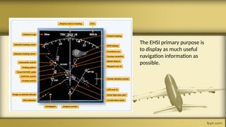
Avionic Instrument History
Classic Instrument Flight
Brief history of Flight Instrument first implementation
- Year 1903:Wright Brothers who invented the first featured flight instrument using a three instruments on board:
a stopwatch to time the length of flights, a "Veedor" engine-revolutions counter to measure engine rpms, and an anemometer
to measure distance. All three of these constructs as “Richard’s Anemometer
-Late 1920s- 1930s:the adoption of direction gyroscopic(now known as a heading
indicator) flight instruments and artificial horizon(also known as an attitude indicator), with attitude and
heading indicators introduced, these allowed pilots to fly “blind,” navigating solely by instruments.
First Person who performed
Flying Blindly Using a Basic
Instrument on September
29th, 1929
1920s-1950s: Development and popularization of VHF Omnidirectional Range (VOR) systems, allowing navigation
via radio signals from ground beacons.
After a brief history that we have seen, is time to take look for basic
understanding within milestone of flight instrument.
SIX PACK FLIGHT
INSTRUMENT??
WHAT IS A SIX PACK
INSTRUMENT??
SIX PACK OF INSTRUMENT
- The six pack instruments form the foundation of flight navigation
and safety, you can say if you don’t have this you don’t permitted
to flight if you BLIND DIRECTION!
It’s Consist of:
1. Altitude Meter/Altimeter
2. Attitude Indicator/Artificial Horizon
3. Vertical Speed Indicator(VSI)
4. Airspeed Indicator
5.Heading Indicator/Direct Gyroscope
6. Turn Indicator
AIRSPEED INDICATOR(ASi)
The airspeed indicator, a primary pitot-static instrument, measures how fast the
aircraft is moving through the air. It compares the ram air pressure (from the pitot
tube) and the static air pressure (from the static port). The difference between these
pressures gives the dynamic pressure corresponding to the aircraft's speed. Several
critical speeds are color-coded on ASIs, including stall speeds and maximum allowable
speeds, ensuring pilots operate within safe parameters.
Green signifies the normal operating range. White indicates the flap operating range
(when flaps can be utilized safely.) Yellow is the caution range. The red line shows the
maximum speed that should not be exceeded.
ALTIMETER
The altimeter, indicates the aircraft's altitude above mean sea level (AMSL). It
measures static air pressure from the static port and converts it into a height reading.
As atmospheric pressure decreases with altitude, the altimeter can interpret these
changes and display them as altitude variations. Three pointers provide the altitude
information in 100, 1,000 and 10,000 foot increments. Pilots must set their altimeters
to the local barometric pressure to ensure accurate readings, especially during
approaches and landings.
VERTICAL SPEED
INDICATOR(Vsi
The vertical speed Indicator showcases how quickly the aircraft ascends or descends. It
measures the rate of change in static air pressure, translating it into feet per minute
(fpm). This provides real-time feedback to the pilot about the altitude change rate,
which is crucial during climbs, descents and level flight.
PITOT SYSTEM STRUCTURES
ATTITUDE INDICATOR(AI)
Also known as an artificial horizon, the attitude indicator is a gyroscopic instrument. It
provides a visual representation of the aircraft's orientation relative to Earth's horizon.
The AI displays two primary movements: pitch (nose up or down) and bank or roll (tilt
left or right). Inside, a gyroscope spins rapidly and maintains its orientation, allowing
the instrument to display the aircraft's attitude even if external visual references are
lost, such as in cloudy conditions or at night.
TURN COORDINATOR (TC)
The turn coordinator is a combination of gyroscopic functionalities. It consists of two
parts: a turn indicator and an inclinometer. The turn indicator reflects the rate of the
aircraft's yawing motion (turning left or right). The inclinometer, filled with liquid and
featuring a black ball, indicates the quality of the turn – whether it's coordinated or
there's a slip or skid. Together, they offer a comprehensive look at the aircraft's turning
performance.
HEADING INDICATOR
A gyroscopic instrument, the heading indicator (sometimes called the Directional Gyro
or DG), displays the aircraft's direction relative to magnetic north. Unlike a simple
magnetic compass, the HI remains stable during flight maneuvers and is unaffected by
most pitch and bank changes. However, it's subject to gyroscopic drift and precession,
so pilots periodically adjust it using the magnetic compass as a reference.
GYROSCOPIC PRINCIPLE
NOTE: FOR HEADING INDICATOR, IT ONLY REFERENCE DUE TO
EARTH MAGNETIC HORIZON SO DOES NOT INCLUDED ON
GYROSCOPIC PRINCIPLE
1980s:Beginning of the modern avionics era with the introduction of digital displays, replacing analog
gauges and enhancing instrument versatility. Such As EFIS system on Cockpit Displays for more efficient indicator
that based on electrical system.
Electronic Flight Instrument System (EFIS)
Less ambiguity
Easier to read
Simple and clean design
The first instrument that changed from analog to
digital, were the Attitude Indicator (ADI) and the
Horizontal Situation Indicator (HSI)
The EADI is the primary flight instrument used for
aircraft attitude information during flying and
during instrument approach
The EHSI primary purpose is
to display as much useful
navigation information as
possible.
A. Primary Flight Display (PFD)
• Fungsi: Menampilkan informasi seperti kecepatan udara, ketinggian, orientasi pesawat
(attitude), arah pesawat (heading), dan informasi lain yang terkait dengan kontrol penerbangan.
• Fitur: PFD menyatukan beberapa instrumen tradisional menjadi satu tampilan yang kompak,
memudahkan pilot dalam memantau status penerbangan dengan cepat.
B. Multi-Function Display (MFD)
• Fungsi: Menyediakan tampilan peta navigasi, data cuaca, informasi lalu lintas udara, dan data
sistem pesawat lainnya.
• Fitur: MFD dapat disesuaikan untuk menampilkan berbagai jenis informasi sesuai kebutuhan
pilot. Ini memungkinkan pilot untuk mengakses data penting dengan lebih mudah dan efisien.
Electronic Flight Instrument System (EFIS)
PRIMARY FLIGHT DISPLAY
Attitude indicator,
Airspeed indicator,
Vertical speed indicator,
Altimeter,
Turn indicator,
Heading indicator
Flight mode announciator, etc.
MULTI-FUNCTION-DISPLAY
The MFD sets itself apart by having complete
customizability. Most MFDs can display engine
information, traffic, and even charts or checklists.
Navigation
Weather radar
Wind direction and speed
Map
DME
VOR
C. Engine Indicating and Crew Alerting System (EICAS) / Electronic Centralized Aircraft Monitor (ECAM)
• Function: Monitors and displays the status of all critical systems in the aircraft, including the
engines, hydraulics, fuel, and electrical systems.
• Feature: EICAS or ECAM can also alerting pilots to potential issues before they become critical. the
EICAS will display an alert to the pilots, along with information on the severity of the issue and any
recommended actions.
CONTROL PANEL
Allows crew to control the information displayed on the EFIS display
SYMBOL GENERATOR (SG)
It processes the data received from the system
and taking into account the setting selected in
the control panel, generate the images to be
displayed on the screen.
Common Display System (CDS)
Era: 1990-an hingga 2000-an.
GPS (Global Positioning System) (1990-an): Sistem GPS komersial menjadi tersedia,
menyediakan informasi posisi dan navigasi yang sangat akurat, yang mempermudah navigasi
dan meningkatkan keselamatan penerbangan
Karakteristik: CDS adalah sistem tampilan yang semakin umum pada pesawat modern, di
mana berbagai informasi penerbangan ditampilkan pada layar LCD yang dapat dikonfigurasi
sesuai kebutuhan penerbangan.
CDS dirancang untuk mengintegrasikan data dari berbagai sistem avionik, termasuk sistem
navigasi, sistem cuaca, TCAS, EICAS/ECAM, dan FMS, dalam satu atau beberapa layar yang
dapat dikonfigurasi.
CDS memiliki komponen berikut :
a. Display Select Panel (2)
b. Engine Display Control Panel
c. EFIS Control Panel (2)
d. Display Source Selector (2)
e. Display Electronics Unit (2)
f. Coax Coupler (4)
g. Identical Display Unit (6)
h. Brightness Control Panel (2)
i. Remote Light Sensor (2)
Integrated Modern Electronic Instrument
Era: 2000-an sampai sekarang.
GPS (Global Positioning System) (2000-an): Sistem GPS komersial menjadi tersedia,
menyediakan informasi posisi dan navigasi yang sangat akurat, yang mempermudah navigasi
dan meningkatkan keselamatan penerbangan. Sistem GPS yang digunakan memakai
mikrokontroler sebagai daya akurat yang lebih tinggi dari sebelumnya.
Karakteristik: Integrated Modern Electronic Instrument adalah sistem tampilan yang semakin
umum pada pesawat modern, di mana berbagai informasi penerbangan ditampilkan pada layar
LCD yang dapat dikonfigurasi sesuai kebutuhan penerbangan dan menggunakan
mikrokontroller..
Integrated Modern Electronic Instrument dirancang untuk mengintegrasikan data dari berbagai
sistem avionik, termasuk sistem navigasi, sistem cuaca, TCAS, EICAS/ECAM, dan FMS, dalam
satu atau beberapa layar yang dapat dikonfigurasi.
REFERENCE
https://airandspace.si.edu/stories/editorial/octave-chanute-and-richard-anemometer
https://skybrary.aero/articles/vhf-omnidirectional-radio-range-vor
https://www.airpowerinc.com/six-pack-aircraft-instruments
https://pilotinstitute.com/gyroscopic-instruments/

Avionic Instrument History power point.pptx

  • 1.
  • 2.
  • 3.
    Brief history ofFlight Instrument first implementation - Year 1903:Wright Brothers who invented the first featured flight instrument using a three instruments on board: a stopwatch to time the length of flights, a "Veedor" engine-revolutions counter to measure engine rpms, and an anemometer to measure distance. All three of these constructs as “Richard’s Anemometer
  • 4.
    -Late 1920s- 1930s:theadoption of direction gyroscopic(now known as a heading indicator) flight instruments and artificial horizon(also known as an attitude indicator), with attitude and heading indicators introduced, these allowed pilots to fly “blind,” navigating solely by instruments. First Person who performed Flying Blindly Using a Basic Instrument on September 29th, 1929
  • 5.
    1920s-1950s: Development andpopularization of VHF Omnidirectional Range (VOR) systems, allowing navigation via radio signals from ground beacons.
  • 6.
    After a briefhistory that we have seen, is time to take look for basic understanding within milestone of flight instrument. SIX PACK FLIGHT INSTRUMENT??
  • 7.
    WHAT IS ASIX PACK INSTRUMENT??
  • 8.
    SIX PACK OFINSTRUMENT - The six pack instruments form the foundation of flight navigation and safety, you can say if you don’t have this you don’t permitted to flight if you BLIND DIRECTION!
  • 9.
    It’s Consist of: 1.Altitude Meter/Altimeter 2. Attitude Indicator/Artificial Horizon 3. Vertical Speed Indicator(VSI) 4. Airspeed Indicator 5.Heading Indicator/Direct Gyroscope 6. Turn Indicator
  • 11.
    AIRSPEED INDICATOR(ASi) The airspeedindicator, a primary pitot-static instrument, measures how fast the aircraft is moving through the air. It compares the ram air pressure (from the pitot tube) and the static air pressure (from the static port). The difference between these pressures gives the dynamic pressure corresponding to the aircraft's speed. Several critical speeds are color-coded on ASIs, including stall speeds and maximum allowable speeds, ensuring pilots operate within safe parameters. Green signifies the normal operating range. White indicates the flap operating range (when flaps can be utilized safely.) Yellow is the caution range. The red line shows the maximum speed that should not be exceeded.
  • 12.
    ALTIMETER The altimeter, indicatesthe aircraft's altitude above mean sea level (AMSL). It measures static air pressure from the static port and converts it into a height reading. As atmospheric pressure decreases with altitude, the altimeter can interpret these changes and display them as altitude variations. Three pointers provide the altitude information in 100, 1,000 and 10,000 foot increments. Pilots must set their altimeters to the local barometric pressure to ensure accurate readings, especially during approaches and landings.
  • 13.
    VERTICAL SPEED INDICATOR(Vsi The verticalspeed Indicator showcases how quickly the aircraft ascends or descends. It measures the rate of change in static air pressure, translating it into feet per minute (fpm). This provides real-time feedback to the pilot about the altitude change rate, which is crucial during climbs, descents and level flight.
  • 14.
  • 15.
    ATTITUDE INDICATOR(AI) Also knownas an artificial horizon, the attitude indicator is a gyroscopic instrument. It provides a visual representation of the aircraft's orientation relative to Earth's horizon. The AI displays two primary movements: pitch (nose up or down) and bank or roll (tilt left or right). Inside, a gyroscope spins rapidly and maintains its orientation, allowing the instrument to display the aircraft's attitude even if external visual references are lost, such as in cloudy conditions or at night.
  • 16.
    TURN COORDINATOR (TC) Theturn coordinator is a combination of gyroscopic functionalities. It consists of two parts: a turn indicator and an inclinometer. The turn indicator reflects the rate of the aircraft's yawing motion (turning left or right). The inclinometer, filled with liquid and featuring a black ball, indicates the quality of the turn – whether it's coordinated or there's a slip or skid. Together, they offer a comprehensive look at the aircraft's turning performance.
  • 17.
    HEADING INDICATOR A gyroscopicinstrument, the heading indicator (sometimes called the Directional Gyro or DG), displays the aircraft's direction relative to magnetic north. Unlike a simple magnetic compass, the HI remains stable during flight maneuvers and is unaffected by most pitch and bank changes. However, it's subject to gyroscopic drift and precession, so pilots periodically adjust it using the magnetic compass as a reference.
  • 18.
    GYROSCOPIC PRINCIPLE NOTE: FORHEADING INDICATOR, IT ONLY REFERENCE DUE TO EARTH MAGNETIC HORIZON SO DOES NOT INCLUDED ON GYROSCOPIC PRINCIPLE
  • 19.
    1980s:Beginning of themodern avionics era with the introduction of digital displays, replacing analog gauges and enhancing instrument versatility. Such As EFIS system on Cockpit Displays for more efficient indicator that based on electrical system. Electronic Flight Instrument System (EFIS)
  • 20.
    Less ambiguity Easier toread Simple and clean design
  • 21.
    The first instrumentthat changed from analog to digital, were the Attitude Indicator (ADI) and the Horizontal Situation Indicator (HSI)
  • 23.
    The EADI isthe primary flight instrument used for aircraft attitude information during flying and during instrument approach
  • 24.
    The EHSI primarypurpose is to display as much useful navigation information as possible.
  • 25.
    A. Primary FlightDisplay (PFD) • Fungsi: Menampilkan informasi seperti kecepatan udara, ketinggian, orientasi pesawat (attitude), arah pesawat (heading), dan informasi lain yang terkait dengan kontrol penerbangan. • Fitur: PFD menyatukan beberapa instrumen tradisional menjadi satu tampilan yang kompak, memudahkan pilot dalam memantau status penerbangan dengan cepat. B. Multi-Function Display (MFD) • Fungsi: Menyediakan tampilan peta navigasi, data cuaca, informasi lalu lintas udara, dan data sistem pesawat lainnya. • Fitur: MFD dapat disesuaikan untuk menampilkan berbagai jenis informasi sesuai kebutuhan pilot. Ini memungkinkan pilot untuk mengakses data penting dengan lebih mudah dan efisien. Electronic Flight Instrument System (EFIS)
  • 27.
    PRIMARY FLIGHT DISPLAY Attitudeindicator, Airspeed indicator, Vertical speed indicator, Altimeter, Turn indicator, Heading indicator Flight mode announciator, etc.
  • 28.
    MULTI-FUNCTION-DISPLAY The MFD setsitself apart by having complete customizability. Most MFDs can display engine information, traffic, and even charts or checklists. Navigation Weather radar Wind direction and speed Map DME VOR
  • 29.
    C. Engine Indicatingand Crew Alerting System (EICAS) / Electronic Centralized Aircraft Monitor (ECAM) • Function: Monitors and displays the status of all critical systems in the aircraft, including the engines, hydraulics, fuel, and electrical systems. • Feature: EICAS or ECAM can also alerting pilots to potential issues before they become critical. the EICAS will display an alert to the pilots, along with information on the severity of the issue and any recommended actions.
  • 31.
    CONTROL PANEL Allows crewto control the information displayed on the EFIS display
  • 32.
    SYMBOL GENERATOR (SG) Itprocesses the data received from the system and taking into account the setting selected in the control panel, generate the images to be displayed on the screen.
  • 35.
    Common Display System(CDS) Era: 1990-an hingga 2000-an. GPS (Global Positioning System) (1990-an): Sistem GPS komersial menjadi tersedia, menyediakan informasi posisi dan navigasi yang sangat akurat, yang mempermudah navigasi dan meningkatkan keselamatan penerbangan Karakteristik: CDS adalah sistem tampilan yang semakin umum pada pesawat modern, di mana berbagai informasi penerbangan ditampilkan pada layar LCD yang dapat dikonfigurasi sesuai kebutuhan penerbangan. CDS dirancang untuk mengintegrasikan data dari berbagai sistem avionik, termasuk sistem navigasi, sistem cuaca, TCAS, EICAS/ECAM, dan FMS, dalam satu atau beberapa layar yang dapat dikonfigurasi.
  • 36.
    CDS memiliki komponenberikut : a. Display Select Panel (2) b. Engine Display Control Panel c. EFIS Control Panel (2) d. Display Source Selector (2) e. Display Electronics Unit (2) f. Coax Coupler (4) g. Identical Display Unit (6) h. Brightness Control Panel (2) i. Remote Light Sensor (2)
  • 38.
    Integrated Modern ElectronicInstrument Era: 2000-an sampai sekarang. GPS (Global Positioning System) (2000-an): Sistem GPS komersial menjadi tersedia, menyediakan informasi posisi dan navigasi yang sangat akurat, yang mempermudah navigasi dan meningkatkan keselamatan penerbangan. Sistem GPS yang digunakan memakai mikrokontroler sebagai daya akurat yang lebih tinggi dari sebelumnya. Karakteristik: Integrated Modern Electronic Instrument adalah sistem tampilan yang semakin umum pada pesawat modern, di mana berbagai informasi penerbangan ditampilkan pada layar LCD yang dapat dikonfigurasi sesuai kebutuhan penerbangan dan menggunakan mikrokontroller.. Integrated Modern Electronic Instrument dirancang untuk mengintegrasikan data dari berbagai sistem avionik, termasuk sistem navigasi, sistem cuaca, TCAS, EICAS/ECAM, dan FMS, dalam satu atau beberapa layar yang dapat dikonfigurasi.
  • 39.