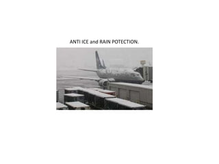
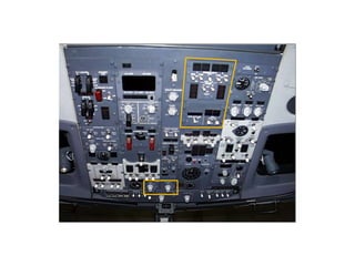
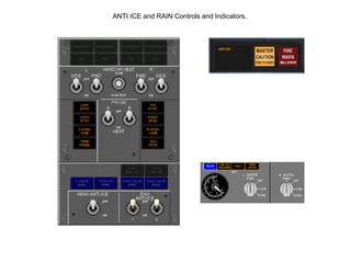
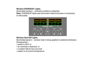
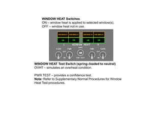
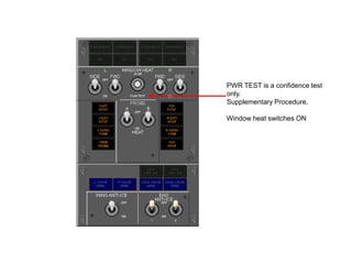
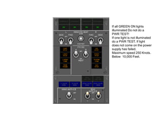
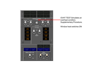
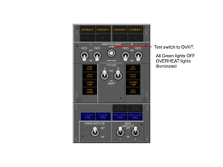
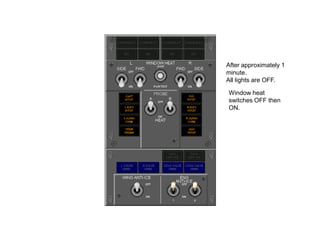
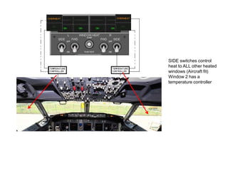
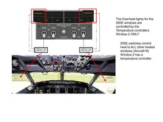
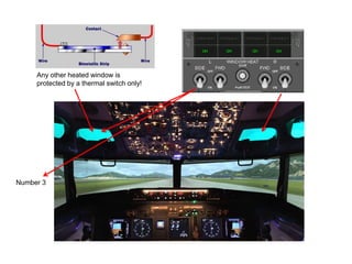
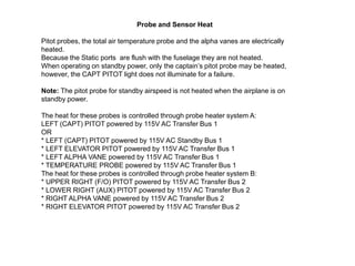
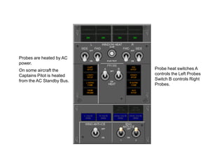
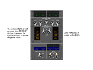
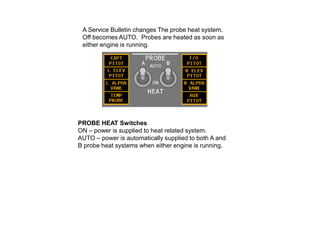
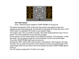
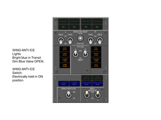
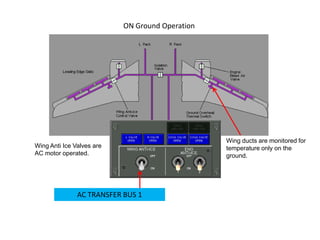
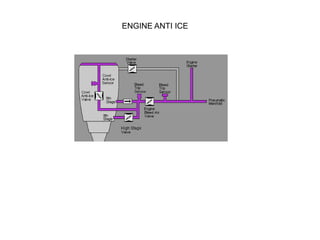
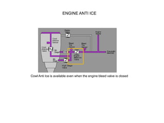
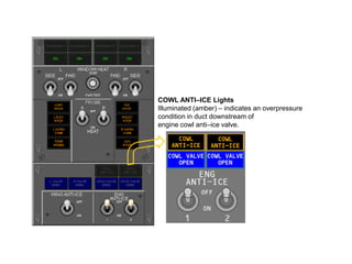
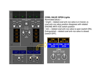
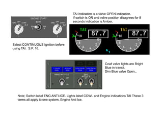
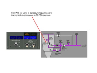
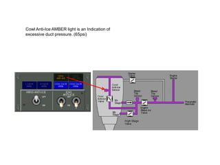
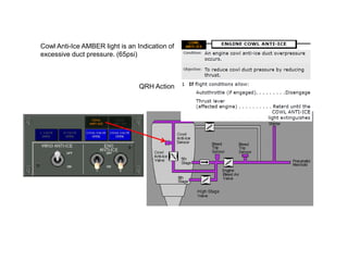
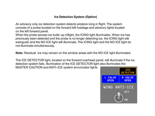
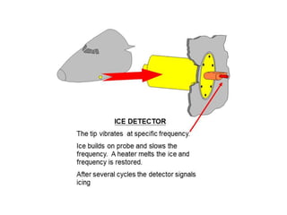
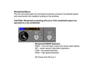
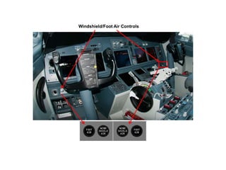
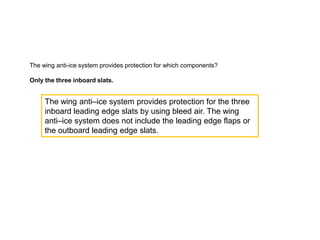
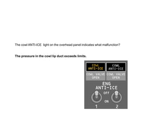
The document provides information on anti-ice and rain protection systems for the Boeing 737 NG, including thermal anti-icing, electrical anti-icing, and windshield wipers. It describes the flight deck window heat, probe and sensor heat, engine anti-ice system, wing anti-ice system, ice detection system, and corresponding controls and indicators. The wing and engine anti-ice systems use bleed air to prevent ice buildup, while probes and sensors are heated electrically. Lights indicate system status and faults like overheat conditions.
This document provides an overview of the autopilot flight director system (AFDS) on the Boeing 737-800, with a focus on takeoff, climb, cruise, descent, and approach phases of flight. It describes the various autopilot modes including takeoff/go-around (TO/GA), level change (LVL CHG), vertical speed (V/S), altitude hold (ALT HOLD), and approach (APP). It also discusses automatic throttle modes like N1 and speed hold, as well as reversion modes for minimum and maximum speeds.
The document provides information on the engines and engine systems of the Boeing 737 NG. It describes the dual CFM56-7 turbofan engines in detail, including the N1 and N2 rotors. It also outlines the electronic engine control (EEC), engine fuel and oil systems, and normal and alternate engine instrument displays. Key details covered include the EEC modes, engine instrumentation, fuel shutoff valves, oil temperature and pressure monitoring, and engine fault indications.
The document provides information on warning systems for the Boeing 737 NG, including visual, aural and tactile warnings. It describes conditions that trigger red warning lights for issues that require immediate attention, such as engine fires. Amber caution lights indicate issues needing timely attention. Blue, green and dim/bright blue lights provide non-critical information. The stick shaker and aural warnings alert to impending stalls. Ground proximity warning systems monitor altitude and terrain clearance in different phases of flight.
The document provides information about the auxiliary power unit (APU) on the Boeing 737 NG aircraft. It discusses the APU components, operation, controls, limitations and shutdown procedures. The APU supplies bleed air and electrical power when the main engines are not running. It can operate up to the aircraft's maximum certified altitude and has automatic shutdown protections for conditions like overspeed, low oil pressure or high exhaust gas temperatures.
1. The Boeing 737's electrical power system uses two engine-driven generators and an APU generator to provide power to two transfer busses, which can be configured via bus tie breakers to power both busses.
2. External ground power or the APU generator can each power both busses by connecting to a tie bus, but they are never paralleled on the tie bus and selection of one will remove the other.
3. The two engine generators can each power their respective transfer bus while external power or the APU continues powering the other bus through the tie bus configuration.
The Common Display System (CDS) supplies navigation and engine information to pilots using 6 identical display units. The CDS uses 2 Display Electronics Units (DEU) that collect data and convert it to video signals for the displays. Either DEU can supply all displays if one fails. The Primary Flight Display normally appears on the outboard display unit while the Navigation Display is on the inboard unit. Engine indications are usually on the upper display unit. The lower display unit shows secondary engine information and can be configured as a multifunction display.
The document provides information on fire protection systems for the B 737 NG, including engine, APU, cargo compartment, main wheel well, and lavatory fire protection. It describes the detection and extinguishing systems for each area. Engine fire detection uses dual gas pressure detector loops to sense overheat or fire conditions. The engines and APU have fire extinguishing bottles that discharge halon when the fire switch is activated. Cargo compartments have smoke detectors in dual loops and can be select to single loop operation. Main wheel wells and lavatories have smoke or heat detection but no extinguishing systems.
The document provides information on the landing gear system of the Boeing 737 NG. It describes the main components and operation of the landing gear including:
- The aircraft has two main landing gears and a single nose gear.
- Hydraulic system A normally controls extension, retraction and nose wheel steering. System B provides alternatives.
- Extension and retraction are controlled by the landing gear lever and occur through hydraulic pressure and mechanical locks.
- Sensors monitor gear position and provide inputs to warning systems.
- Manual extension is possible if system A fails using gear releases.
The document summarizes the hydraulic systems on a Boeing 737 NG, including:
- There are three hydraulic systems - A, B, and a standby system that acts as backup if the other systems lose pressure.
- Systems A and B each have an engine-driven pump and electric pump, while the standby only has an electric pump.
- The systems power various flight controls and other aircraft components. The standby system can power the rudder, thrust reversers, and leading edge flaps if needed.
- The document describes components, indications, and manual or automatic activation methods for the standby system in the event of issues with systems A or B.
The document provides information on the pneumatic and bleed air systems of the Boeing 737 NG. It discusses how bleed air is supplied by the engines or APU to systems like air conditioning, anti-icing, and hydraulics. Key components discussed include the engine bleed valves, isolation valve, packs, and ram air system. The bleed air is regulated and cooled before being supplied to the air conditioning system to produce conditioned air for the aircraft.
The autopilot flight director system (AFDS) consists of two flight control computers and a mode control panel. The AFDS and autothrottle are controlled automatically by the flight management computer to fly the optimized flight path. The mode control panel is used to select AFDS and autothrottle modes, with engaged modes annunciated on the flight mode annunciator. The flight director displays command guidance for the pilot when engaged but does not provide flare guidance for landing.
This document provides information about the B737 NG ground school including:
1) A link to a study guide for the aircraft.
2) Details about the flight deck door including locking mechanisms and a viewing lens.
3) Description of the flight deck access system including a keypad, indicator lights, and access code.
4) Information on the emergency decompression panels and their manual release.
The document provides information about the flight control systems on the Boeing 737 NG, including:
- The primary flight controls (ailerons, elevators, rudder) are powered by redundant hydraulic systems and can operate manually if needed.
- Secondary flight controls like flaps and slats are powered by hydraulic system B or have emergency electric operation.
- The document then describes the various flight control components in more detail, including ailerons, spoilers, elevators, stabilizer, and related switches.
The document discusses the Air Data Inertial Reference System (ADIRS) on the Boeing 737 NG. The ADIRS contains two air data inertial reference units (ADIRUs) that each have an air data computer and inertial reference system. The ADIRS provides flight data like position, speed, altitude and attitude to other aircraft systems. It aligns using the aircraft's position, earth's rotation, and gravity to calculate latitude but not longitude.
The document provides information about the communication systems on a B737 aircraft, including:
- The radio communication, interphone, cockpit voice recorder, and communication crew alerting systems.
- The audio control panels, radio tuning panels, and radio communication panels used to control the communication systems.
- Details on the audio systems, audio control panels, microphones, radio tuning panels, and limitations of the communication systems. It describes normal operation and what to do in case of degraded audio system operation.
This document provides a summary of a presentation on conducting an exterior inspection of the Boeing 737 aircraft. The presentation covers inspections of the classic and next generation 737 according to Boeing procedures. It is divided into chapters on general guidelines, conducting the walk-around inspection, cold weather operations, and the top 10 blunders to avoid. The inspection involves checking various components and surfaces for damage, leaks, cleanliness, and security.
This document provides an overview of a maintenance and engineering training class on the master warning and caution lights on a Boeing 737-800 aircraft. The class will cover locating major components and describing their functions, panel operation and interface, electrical power distribution and control, routine servicing, minimum equipment lists, and troubleshooting. It provides information on the annunciator and dimming module location, its interface with other aircraft systems, recall check procedures, lamp replacement, and asks review questions at the end.
This document provides an overview of the Boeing 737 Next Generation flight management computer system (FMC). It describes the key components of the flight management system including the FMC, autopilot, inertial reference systems, and GPS. It explains that the FMC is at the heart of the system, performing navigational computations and providing control commands. It also provides details on how crew interact with the system through control display units to enter flight plans and monitor performance.
The document provides information on the Boeing 737 NG fuel system. It describes the three fuel tanks, their capacities and fuel quantity indicators. It outlines the fuel pumps, valves and controls. It notes limitations on fuel temperature, imbalance and loading. Procedures for refueling, defueling and cross-feeding fuel between tanks are summarized.
This document provides an overview of the electrical power system on a Boeing 747-400 aircraft. It describes the various AC and DC power buses, and how electrical power is generated, distributed, and controlled throughout normal operations and different failure conditions. Key components include the integrated drive generators, transformer rectifier units, batteries, and external power connections.
- The document presents a seminar on aircraft cabin pressurization systems given by Mr. Shrinivas Kale.
- It includes sections on introduction, literature review, problem formulation, objectives, methodology, hypothesis, work plan and references.
- The literature review summarizes several papers on topics related to aircraft cabin pressurization, environmental control systems, and thermal comfort experiments.
The document describes the fire protection systems on an aircraft, including smoke detection and fire extinguishing systems for the crew rest compartment, lavatories, wheel wells, pneumatic ducts, cargo compartments, and engines. It provides details on the components, locations, and functions of the smoke detectors, fire detectors, fire extinguishing bottles, and test buttons for these various systems.
The document summarizes several key differences between the Boeing 737 Classic (CL) and Next Generation (NG) aircraft models. Some key differences include:
- The NG uses retractable landing lights and logo lights are relocated.
- The pressurization and electrical systems were upgraded on the NG.
- The NG has improved engines, updated engine controls, and an increased APU capability.
- Additional or relocated emergency equipment, lighting, and several system upgrades were implemented on the NG.
The document discusses the flight control systems of the Boeing 747-400, including descriptions of:
1) The aileron, spoiler, elevator, rudder, and flap control systems. It describes the components and functions of each system.
2) The modes of operation for the flap control system including primary, secondary, and alternate modes. It provides details on flap sequencing and position indication.
3) Indications that may appear related to problems with the flight control systems like disagreements between sensors or failures in certain components.
1. The A380 is a large, double-deck widebody airliner with seating for 644-868 passengers.
2. The A380 landing gear system includes wheels, brakes, doors and related control computers and devices to extend, retract, steer and brake the landing gear.
3. The landing gear consists of two wing landing gears, two body landing gears, and a nose landing gear, each with related doors and retraction/extension mechanisms.
Diamond Twinstar DA-42 Overview. This slideshow is used in conjunction with Fly Corps Aviation's Multiengine Program, including Commercial Multiengine, Multiengine Instructor, and ATP Training course at KSAV in Savannah Georgia. Visit www.flycorps.com to learn more!
This document provides a description and overview of the autopilot and yaw damper system for a B727-200 aircraft. It describes the major components, including the Sperry SP-50 MB V Automatic Flight Control System, which provides three-axis flight stabilization and automatic approach capability. It details the functions of the yaw, roll, and pitch axes, and describes the components that control and provide inputs to each axis, such as rudder power units, aileron servos, elevator power units, and sensors. The document also notes the locations of components throughout the aircraft.
Manual of Thermostat Fan Coil 4Pipes MH8 series - MCO HOME Domotica daVinci
The document is a user manual for the MCOHome Fan Coil Thermostat, a Z-Wave enabled device for indoor temperature control in a 4-pipe fan coil system. It can automatically control fan speed based on temperature difference and read temperature and time. The manual describes features like touch buttons, temperature calibration, memory backup, and intelligent fan and valve control. It provides specifications, safety information, installation instructions, and explains how to operate, set parameters and configure the thermostat for a Z-Wave network.
The document provides information about testing engine coolant temperature (ECT) sensors, including:
1) ECT sensors measure engine coolant temperature which the computer uses to control spark timing, fuel mixture, and other functions.
2) ECT sensors have high resistance when cold and low resistance when hot, exhibiting a negative temperature coefficient.
3) ECT sensors can be tested by measuring resistance with a multimeter and comparing to specifications, or by comparing the temperature displayed on a scan tool to the actual coolant temperature.
This document provides information about servicing the overhead console in a Dakota vehicle. It describes components like the compass, thermometer, reading lamps, and storage compartments. The summary is:
The document outlines diagnosis and service procedures for the overhead console in a Dakota, including how to test the compass and thermometer, demagnetize the vehicle roof if needed, and remove/replace various components like the console, modules, bezels, storage doors, bins, and dampers. General information is provided on the compass, thermometer, lamps, and storage features, along with diagnostic tests and troubleshooting steps.
The SP series solar working station controls split-system solar hot water heating systems. It connects the solar collectors and pressurized water tank to efficiently convert solar energy into heat. As the heart of the system, it ensures safety and allows remote monitoring/control via an app. Its touchscreen interface displays operating parameters and system status. The station can integrate up to 39 systems and includes pumps, sensors, and relays to circulate water and trigger auxiliary heating based on temperature thresholds and schedules. Firmware updates allow customizing controls to user needs.
This document provides information about the air conditioning system used in LHB AC coaches in India. It discusses the need for air conditioning in railway coaches given India's climate. It then describes the main components of the air conditioning system in LHB coaches, including the RMPU unit, ducting system, and control mechanisms. It explains the vapor compression refrigeration cycle and summarizes the different operating modes of the RMPU unit like pre-heating, pre-cooling, cooling, heating and shutdown.
This document is a user manual for the MCOHome Fan Coil Thermostat, a Z-Wave enabled device for indoor temperature control in a 2-pipe fan coil system. It can automatically control fan speed based on temperature difference and is reliable and practical. Key features include capacitive touch buttons, precise temperature calibration, and intelligent fan and valve control. It has an AC power supply, displays temperature accurately to 0.1 degrees Celsius, and has a dimension of 86x86x42mm. Installation instructions provide guidelines on location and wiring. The manual also describes the thermostat's settings, parameters, Z-Wave functionality, and 1-year limited warranty.
The pneumatic system provides compressed air for aircraft functions like air conditioning, engine starting, and anti-ice systems. It obtains air from the engine bleed ports and controls the air pressure, temperature, and cleanliness. Leak detection loops monitor the hot air ducts and can isolate leaks by closing valves. The pneumatic system is controlled and monitored via panels and ECAM displays.
Anole hot runner temperature control systems in China use high intelligent, smart meter & a computer chip as hot runner mould temperature controller and have multiple digital filter to provide the PID algorithm & realize accurate temperature control of the Hot Runner.
This document provides specifications for MacQuay mini air-cooled chiller models MAC 040A/AR through MAC 125B/BR. It details the units' features such as their compact design with separate refrigerant and water circuits, environmentally friendly R22 refrigerant charging, and versatility to couple with fan coil units. It also provides information on the units' components, refrigeration circuit, safety controls, antifreeze protection, standard factory settings, and microprocessor controller functions.
This document describes the specifications of a stability test chamber made by R Technologies PVT Ltd. It has double walled stainless steel construction with glass wool insulation. The chamber maintains temperature from 10-60°C and humidity from 40-95% RH. It has microprocessor controls for temperature, humidity, illumination and data logging. The chamber also has alarms, adjustable shelves and is powered by 230V AC.
Weiber Stability Test Chambers/ are widely used for
confirmatory studies for direct comparison of drug
substance under controlled environmental conditions.
This document provides information about heating and air conditioning systems. It discusses the components and operation of both manual and automatic temperature control systems. It covers the heater core, evaporator, condenser, compressor, refrigerant lines, and sensors. It provides warnings and cautions for safely servicing the A/C system. Refrigerant R-134a is used, which requires special equipment, hoses, and oil compared to R-12.
This document describes operation instructions for a solar water heating control system work station. It includes:
1. An overview of the work station components, technical specifications, and display signals.
2. Descriptions of 8 possible solar system configurations that can be controlled by the work station, involving combinations of collectors, storage tanks, pumps, and valves.
3. Safety information and instructions for installing, operating, and maintaining the work station.
The document provides information about the ice and rain protection systems for the A300 and A310 aircraft. It describes that critical areas like the wing slats and engine intakes are heated using hot air from the engines or APU. The wing anti-ice system uses hot bleed air through valves to heat the leading edges of the center and outer wing slats. The document includes diagrams of the system components and descriptions of the indicator lights for system operation.
This thermostat has an LCD screen and capacitive touch buttons. It can control electric heating devices up to 16A and has integrated sensors for temperature, humidity, light, and energy consumption. It uses Z-Wave to connect to home automation systems and control up to 10 additional devices. The six operating modes include comfort, time-based, drying, energy-saving, vacation, and manual modes. Technical specifications include dimensions, materials, temperature ranges, accuracy, power requirements, and more.
Removing Uninteresting Bytes in Software FuzzingAftab Hussain
Imagine a world where software fuzzing, the process of mutating bytes in test seeds to uncover hidden and erroneous program behaviors, becomes faster and more effective. A lot depends on the initial seeds, which can significantly dictate the trajectory of a fuzzing campaign, particularly in terms of how long it takes to uncover interesting behaviour in your code. We introduce DIAR, a technique designed to speedup fuzzing campaigns by pinpointing and eliminating those uninteresting bytes in the seeds. Picture this: instead of wasting valuable resources on meaningless mutations in large, bloated seeds, DIAR removes the unnecessary bytes, streamlining the entire process.
In this work, we equipped AFL, a popular fuzzer, with DIAR and examined two critical Linux libraries -- Libxml's xmllint, a tool for parsing xml documents, and Binutil's readelf, an essential debugging and security analysis command-line tool used to display detailed information about ELF (Executable and Linkable Format). Our preliminary results show that AFL+DIAR does not only discover new paths more quickly but also achieves higher coverage overall. This work thus showcases how starting with lean and optimized seeds can lead to faster, more comprehensive fuzzing campaigns -- and DIAR helps you find such seeds.
- These are slides of the talk given at IEEE International Conference on Software Testing Verification and Validation Workshop, ICSTW 2022.
Pushing the limits of ePRTC: 100ns holdover for 100 daysAdtran
At WSTS 2024, Alon Stern explored the topic of parametric holdover and explained how recent research findings can be implemented in real-world PNT networks to achieve 100 nanoseconds of accuracy for up to 100 days.
Maruthi Prithivirajan, Head of ASEAN & IN Solution Architecture, Neo4j
Get an inside look at the latest Neo4j innovations that enable relationship-driven intelligence at scale. Learn more about the newest cloud integrations and product enhancements that make Neo4j an essential choice for developers building apps with interconnected data and generative AI.
Securing your Kubernetes cluster_ a step-by-step guide to success !KatiaHIMEUR1
Today, after several years of existence, an extremely active community and an ultra-dynamic ecosystem, Kubernetes has established itself as the de facto standard in container orchestration. Thanks to a wide range of managed services, it has never been so easy to set up a ready-to-use Kubernetes cluster.
However, this ease of use means that the subject of security in Kubernetes is often left for later, or even neglected. This exposes companies to significant risks.
In this talk, I'll show you step-by-step how to secure your Kubernetes cluster for greater peace of mind and reliability.
Full-RAG: A modern architecture for hyper-personalizationZilliz
Mike Del Balso, CEO & Co-Founder at Tecton, presents "Full RAG," a novel approach to AI recommendation systems, aiming to push beyond the limitations of traditional models through a deep integration of contextual insights and real-time data, leveraging the Retrieval-Augmented Generation architecture. This talk will outline Full RAG's potential to significantly enhance personalization, address engineering challenges such as data management and model training, and introduce data enrichment with reranking as a key solution. Attendees will gain crucial insights into the importance of hyperpersonalization in AI, the capabilities of Full RAG for advanced personalization, and strategies for managing complex data integrations for deploying cutting-edge AI solutions.
Encryption in Microsoft 365 - ExpertsLive Netherlands 2024Albert Hoitingh
In this session I delve into the encryption technology used in Microsoft 365 and Microsoft Purview. Including the concepts of Customer Key and Double Key Encryption.
Epistemic Interaction - tuning interfaces to provide information for AI supportAlan Dix
Paper presented at SYNERGY workshop at AVI 2024, Genoa, Italy. 3rd June 2024
https://alandix.com/academic/papers/synergy2024-epistemic/
As machine learning integrates deeper into human-computer interactions, the concept of epistemic interaction emerges, aiming to refine these interactions to enhance system adaptability. This approach encourages minor, intentional adjustments in user behaviour to enrich the data available for system learning. This paper introduces epistemic interaction within the context of human-system communication, illustrating how deliberate interaction design can improve system understanding and adaptation. Through concrete examples, we demonstrate the potential of epistemic interaction to significantly advance human-computer interaction by leveraging intuitive human communication strategies to inform system design and functionality, offering a novel pathway for enriching user-system engagements.
Generative AI Deep Dive: Advancing from Proof of Concept to ProductionAggregage
Join Maher Hanafi, VP of Engineering at Betterworks, in this new session where he'll share a practical framework to transform Gen AI prototypes into impactful products! He'll delve into the complexities of data collection and management, model selection and optimization, and ensuring security, scalability, and responsible use.
zkStudyClub - Reef: Fast Succinct Non-Interactive Zero-Knowledge Regex ProofsAlex Pruden
This paper presents Reef, a system for generating publicly verifiable succinct non-interactive zero-knowledge proofs that a committed document matches or does not match a regular expression. We describe applications such as proving the strength of passwords, the provenance of email despite redactions, the validity of oblivious DNS queries, and the existence of mutations in DNA. Reef supports the Perl Compatible Regular Expression syntax, including wildcards, alternation, ranges, capture groups, Kleene star, negations, and lookarounds. Reef introduces a new type of automata, Skipping Alternating Finite Automata (SAFA), that skips irrelevant parts of a document when producing proofs without undermining soundness, and instantiates SAFA with a lookup argument. Our experimental evaluation confirms that Reef can generate proofs for documents with 32M characters; the proofs are small and cheap to verify (under a second).
Paper: https://eprint.iacr.org/2023/1886
GraphSummit Singapore | The Future of Agility: Supercharging Digital Transfor...Neo4j
Leonard Jayamohan, Partner & Generative AI Lead, Deloitte
This keynote will reveal how Deloitte leverages Neo4j’s graph power for groundbreaking digital twin solutions, achieving a staggering 100x performance boost. Discover the essential role knowledge graphs play in successful generative AI implementations. Plus, get an exclusive look at an innovative Neo4j + Generative AI solution Deloitte is developing in-house.
Essentials of Automations: The Art of Triggers and Actions in FMESafe Software
In this second installment of our Essentials of Automations webinar series, we’ll explore the landscape of triggers and actions, guiding you through the nuances of authoring and adapting workspaces for seamless automations. Gain an understanding of the full spectrum of triggers and actions available in FME, empowering you to enhance your workspaces for efficient automation.
We’ll kick things off by showcasing the most commonly used event-based triggers, introducing you to various automation workflows like manual triggers, schedules, directory watchers, and more. Plus, see how these elements play out in real scenarios.
Whether you’re tweaking your current setup or building from the ground up, this session will arm you with the tools and insights needed to transform your FME usage into a powerhouse of productivity. Join us to discover effective strategies that simplify complex processes, enhancing your productivity and transforming your data management practices with FME. Let’s turn complexity into clarity and make your workspaces work wonders!
Threats to mobile devices are more prevalent and increasing in scope and complexity. Users of mobile devices desire to take full advantage of the features
available on those devices, but many of the features provide convenience and capability but sacrifice security. This best practices guide outlines steps the users can take to better protect personal devices and information.
Observability Concepts EVERY Developer Should Know -- DeveloperWeek Europe.pdfPaige Cruz
Monitoring and observability aren’t traditionally found in software curriculums and many of us cobble this knowledge together from whatever vendor or ecosystem we were first introduced to and whatever is a part of your current company’s observability stack.
While the dev and ops silo continues to crumble….many organizations still relegate monitoring & observability as the purview of ops, infra and SRE teams. This is a mistake - achieving a highly observable system requires collaboration up and down the stack.
I, a former op, would like to extend an invitation to all application developers to join the observability party will share these foundational concepts to build on:
Unlocking Productivity: Leveraging the Potential of Copilot in Microsoft 365, a presentation by Christoforos Vlachos, Senior Solutions Manager – Modern Workplace, Uni Systems
Unlock the Future of Search with MongoDB Atlas_ Vector Search Unleashed.pdfMalak Abu Hammad
Discover how MongoDB Atlas and vector search technology can revolutionize your application's search capabilities. This comprehensive presentation covers:
* What is Vector Search?
* Importance and benefits of vector search
* Practical use cases across various industries
* Step-by-step implementation guide
* Live demos with code snippets
* Enhancing LLM capabilities with vector search
* Best practices and optimization strategies
Perfect for developers, AI enthusiasts, and tech leaders. Learn how to leverage MongoDB Atlas to deliver highly relevant, context-aware search results, transforming your data retrieval process. Stay ahead in tech innovation and maximize the potential of your applications.
#MongoDB #VectorSearch #AI #SemanticSearch #TechInnovation #DataScience #LLM #MachineLearning #SearchTechnology
1. B 737 NG Ground School.
See the aircraft study guide at www.theorycentre.com
The information contained here is for training purposes only. It is of a general nature it is
unamended and does not relate to any individual aircraft. The FCOM must be consulted for
up to date information on any particular aircraft.
4. Introduction
Thermal anti-icing (TAI), electrical anti-icing, and windshield wipers are the systems
provided for ice and rain protection. The anti-ice and rain systems include:
• Flight Deck Window Heat
• Windshield Wipers
• Probe and Sensor Heat
• Engine Anti-Ice System (TAI)
• Wing Anti-Ice System (TAI)
• Ice Detection System (Option available)
Note; Thermal Anti Ice Uses engine bleed air from the compressor carried in ducts
to heat the engine intake lip and the 3 inboard slats.
6. Window OVERHEAT Lights
Illuminated (amber) – overheat condition is detected.
Note: OVERHEAT lights also illuminate if electrical power to window(s)
is interrupted. Note; Overheat is >63⁰ C
Window Heat ON Lights
Illuminated (green) – window heat is being applied to selected window(s).
Extinguished –
• switch is OFF, or
• an overheat is detected, or
• a system failure has occurred
• system is at correct temperature. Window temperature is above 43⁰ C
7. WINDOW HEAT Switches
ON – window heat is applied to selected window(s).
OFF – window heat not in use.
WINDOW HEAT Test Switch (spring–loaded to neutral)
OVHT – simulates an overheat condition.
PWR TEST – provides a confidence test.
Note: Refer to Supplementary Normal Procedures for Window
Heat Test procedures.
8. PWR TEST is a confidence test
only.
Supplementary Procedures.
Window heat switches ON
If window temperature is above
43⁰ C Green on light will not
illuminate.
Momentary power test will apply
power and bring on the green light.
9. If all GREEN ON lights
illuminated Do not do a
PWR TEST!
If one light is not illuminated
do a PWR TEST. If light
does not come on the power
supply has failed.
Maximum speed 250 Knots.
Below 10,000 Feet.
10. OVHT TEST Simulates an
overheat condition.
Supplementary Procedures.
Overheat is >63⁰ C
Window heat switches ON
11. Test switch to OVHT.
All Green lights OFF
OVERHEAT lights
illuminated
13. Window 1 Left and Right.
Window 2
Left and Right
Window 3
Left and Right
Windows
4 and 5
Left and
right as
fitted
14. Flight Deck Window Heat (Various options depending on aircraft)
Flight deck window numbers 1, 2, 4 and 5 consist of glass panes laminated to
each side of a vinyl core. Flight deck window number 4 has an additional vinyl
layer and acrylic sheet laminated to the inside surface. Flight deck window
number 3 consists of two acrylic panes separated by an air space.
A conductive coating on the outer glass pane of window numbers 1 and 2 permits
electrical heating to prevent ice build–up and fogging. A conductive coating on
the inner glass pane of window numbers 4 and 5 permits electrical heating to
prevent fogging. Window number 3 may or may not be electrically heated.
When heated a conductive coating on the inner glass pane of window number 3
permits electrical heating to prevent fogging.
The FWD WINDOW HEAT switches control heat to window number 1. The
SIDE WINDOW HEAT switches control heat to window numbers 2, 3 4 and 5 as
fitted.
Temperature controllers maintain windows numbers 1 and 2 at the correct
temperature to ensure maximum strength of the windows in the event of bird
impact. Power to window numbers 1 and 2 is automatically removed if an
overheat condition is detected.
Thermal switches, located on window number 3, 4 and 5, open and close to
maintain the correct temperature on the windows that are heated .
15. FWD switches control
heat to ONLY
window L1 and R 1
Window temperature is
controlled by a
TEMPERATURE
CONTROLLER which
cycles power ON an
OFF
17. SIDE switches control
heat to ALL other heated
windows (Aircraft fit)
Window 2 has a
temperature controller
18. The Overheat lights for the
SIDE windows are
controlled by the
Temperature controllers
Window 2 ONLY
SIDE switches control
heat to ALL other heated
windows (Aircraft fit)
Window 2 has a
temperature controller
19. Any other heated window is
protected by a thermal switch only!
Number 3
20. Probe and Sensor Heat
Pitot probes, the total air temperature probe and the alpha vanes are electrically
heated.
Because the Static ports are flush with the fuselage they are not heated.
When operating on standby power, only the captain’s pitot probe may be heated,
however, the CAPT PITOT light does not illuminate for a failure.
Note: The pitot probe for standby airspeed is not heated when the airplane is on
standby power.
The heat for these probes is controlled through probe heater system A:
LEFT (CAPT) PITOT powered by 115V AC Transfer Bus 1
OR
* LEFT (CAPT) PITOT powered by 115V AC Standby Bus 1
* LEFT ELEVATOR PITOT powered by 115V AC Transfer Bus 1
* LEFT ALPHA VANE powered by 115V AC Transfer Bus 1
* TEMPERATURE PROBE powered by 115V AC Transfer Bus 1
The heat for these probes is controlled through probe heater system B:
* UPPER RIGHT (F/O) PITOT powered by 115V AC Transfer Bus 2
* LOWER RIGHT (AUX) PITOT powered by 115V AC Transfer Bus 2
* RIGHT ALPHA VANE powered by 115V AC Transfer Bus 2
* RIGHT ELEVATOR PITOT powered by 115V AC Transfer Bus 2
21. Probes are heated by AC
power.
On some aircraft the
Captains Pitot is heated
from the AC Standby Bus.
Probe heat switches A
controls the Left Probes
Switch B controls Right
Probes.
22. The indicator lights are all
powered from DC BUS 1
On Standby power the
lights are not an indication
of system status!
Static Ports are not
heated on the B737.
23. A Service Bulletin changes The probe heat system.
Off becomes AUTO. Probes are heated as soon as
either engine is running.
PROBE HEAT Switches
ON – power is supplied to heat related system.
AUTO – power is automatically supplied to both A and
B probe heat systems when either engine is running.
24. TAT TEST Switch
Push - Electrical power applied to TEMP PROBE on the ground.
The total air temperature (TAT) probe anti-icing system uses electric power and
resistance-type heating elements. Aircraft with an aspirated TAT probe also have a TAT
TEST button. An aspirated TAT Probe is only heated in flight.
The system uses 115v ac and 28v dc power. The probe heating element uses 115v ac
power. The current detection circuit uses 28v dc power.
On the ground, put the control switch to the ON/AUTO position. This energizes a relay
that stops 115v ac power through the current detection circuit to the probe heater.
The amber TEMP PROBE light does not come on.
Pushing the TEST switch (with control switch in ON position) DE energizes the relay .
This lets 115v ac power through the current detection circuit to the probe heater. If the
probe heater does not use current, the circuit causes the amber TEMP PROBE light to
come on.
The TAT probe is heated with 115 VAC in Air mode.
25. Wing Anti–Ice System
The wing anti–ice system provides protection for the three inboard leading edge
slats by using bleed air. The wing anti–ice system does not include the leading
edge flaps or the outboard leading edge slats.
The wing anti–ice control valves are AC motor–operated. With a valve open, bleed air
flows to the three leading edge inboard slats, and is then exhausted overboard. The
wing anti–ice system is effective with the slats in any position.
Wing Anti–Ice System Operation
On the ground, positioning the WING ANTI–ICE switch ON opens both control valves if
thrust on both engines is below the setting for takeoff warning activation and the
temperature inside both wing distribution ducts is less than the thermal switch activation
temperature.
Both valves close if either engine thrust is above the takeoff warning setting or
either temperature sensor senses a duct over temperature. The valves automatically
reopen if thrust on both engines is reduced and both temperature sensors are cool.
With the air/ground sensor in the ground mode and the WING ANTI–ICE switch
ON, the switch remains in the ON position regardless of control valve position.
The WING ANTI–ICE switch automatically trips OFF at lift–off when the air/ground
sensor goes to the air mode.
26. Positioning the WING ANTI–ICE switch to ON in flight:
• opens both control valves
• sets stall warning logic for icing conditions.
Note; Thrust setting logic and duct temperature logic are inhibited in flight.
Note: Stall warning logic adjusts stick shaker and minimum manoeuvre speed
bars on airspeed indications. FMC displayed VREF is not adjusted automatically.
Note: Stall warning logic remains set for icing conditions for the remainder
of the flight, regardless of subsequent WING ANTI–ICE switch position.
Valve position is monitored by the blue VALVE OPEN lights. Duct temperature
and thrust setting logic are disabled and have no affect on control valve operation
in flight.
27. WING ANTI ICE
Lights
Bright blue in Transit
Dim Blue Valve OPEN.
WING ANTI ICE
Switch.
Electrically held in ON
position.
28. ON Ground Operation
Wing Anti Ice Valves are
AC motor operated.
AC TRANSFER BUS 1
Wing ducts are monitored for
temperature only on the
ground.
29. ON Ground Operation
With TO thrust setting the WAI
valves close automatically.
The Switch remains ON.
The Switch is released to OFF with
Air mode.
30. Flight Operation
Only the 3 inboard
slats have WAI
Duct Temperature and Thrust setting logic are inhibited IN FLIGHT
If the switch is on WAI is ON.
31. FUEL FLOW INCREASE 100 PPH or 50 Kg Per Eng = 100 Kg Hr.
Adverse Weather. . . . . . . . . . . . . . . . SP.16
Wing Anti-ice Operation - In Flight
Ice accumulation on the flight deck window frames, windshield
centre post, or on the windshield wiper arm may be used as an
indication of structural icing conditions and the need to turn on wing
anti-ice.
CAUTION: Use of wing anti-ice above approximately FL350 may
cause a dual bleed trip off and possible loss of cabin pressure.
Note: Prolonged operation in icing conditions with the leading edge
and trailing edge flaps extended is not recommended.
Holding in icing conditions with flaps extended is prohibited.
33. ENGINE ANTI ICE
Cowl Anti Ice is available even when the engine bleed valve is closed
34. COWL ANTI–ICE Lights
Illuminated (amber) – indicates an overpressure
condition in duct downstream of
engine cowl anti–ice valve.
35. COWL VALVE OPEN Lights
Illuminated (blue) –
• bright – related cowl anti–ice valve is in transit, or,
cowl anti–ice valve position disagrees with related
ENGINE ANTI–ICE switch position
• dim – related cowl anti–ice valve is open (switch ON).
Extinguished – related cowl anti–ice valve is closed
(switch OFF).
36. Engine Anti–Ice System
Engine bleed air thermal anti–icing prevents the formation of ice on the engine
cowl lip. Engine anti–ice operation is controlled by individual ENG ANTI–ICE switches.
The engine anti–ice system may be operated on the ground and in flight.
Engine Anti–Ice System Operation
Each cowl anti–ice valve is electrically controlled and pressure actuated.
Positioning the ENG ANTI–ICE switches to ON:
• allows engine bleed air to flow through the cowl anti–ice valve for cowl lip anti–icing
• sets stall warning logic for icing conditions.
Note: Stall warning logic adjusts stick shaker and minimum manoeuvre speed bars on
the airspeed indicator. FMC displayed VREF is not adjusted automatically.
Note: Stall warning logic, airspeed indications, and minimum manoeuvre speeds on the
airspeed indicator return to normal when engine anti–ice is positioned OFF if wing anti–
ice has not been used in flight.
If the cowl anti–ice valve fails to move to the position indicated by the ENG ANTI–ICE
switch, the COWL VALVE OPEN light remains illuminated bright blue and an amber TAI
indication illuminates on the CDS after a short delay.
The amber COWL ANTI–ICE light illuminates due to excessive pressure in the duct
leading from the cowl anti–ice valve to the cowl lip.
37. TAI indication is a valve OPEN indication.
If switch is ON and valve position disagrees for 8
seconds indication is Amber.
Select CONTINUOUS Ignition before
using TAI. S.P. 16.
Cowl valve lights are Bright
Blue in transit.
Dim Blue valve Open.,
Note; Switch label ENG ANTI-ICE. Lights label COWL and Engine indications TAI These 3
terms all apply to one system. Engine Anti Ice.
38. Cowl Anti-Ice Valve is a pressure regulating valve
that controls duct pressure to 50 PSI maximum.
39. Cowl Anti-Ice AMBER light is an Indication of
excessive duct pressure. (65psi)
40. Cowl Anti-Ice AMBER light is an Indication of
excessive duct pressure. (65psi)
QRH Action
41. FUEL FLOW INCREASE 200 PPH or 100 Kg Per Eng = 200 Kg Hr.
Adverse Weather. . . . . . . . . . . . . . . . SP.16
Engine Anti-Ice Operation - In Flight
Engine anti–ice must be ON during all flight operations when icing
conditions exist or are anticipated, except during climb and cruise
when the temperature is below -40 C SAT. Engine anti–ice must be
ON before, and during descent in all icing conditions, including
temperatures below -40 C SAT.
When operating in areas of possible icing, activate engine anti–ice
before entering icing conditions.
When engine anti-ice is needed:
ENGINE START switches .....................................CONT PM
ENGINE ANTI-ICE switches ....................................ON PM
42. NOTE; Total fuel Engine and wing anti ice approximately
300 kg hr.
FUEL FLOW INCREASE 200 PPH or 100 Kg Per Eng = 200 Kg Hr.
Adverse Weather. . . . . . . . . . . . . . . . SP.16
Engine Anti-Ice Operation - In Flight
Engine anti–ice must be ON during all flight operations when icing
conditions exist or are anticipated, except during climb and cruise when
the temperature is below -40°C SAT. Engine anti–ice must be ON before,
and during descent in all icing conditions, including temperatures below
-40°C SAT.
When operating in areas of possible icing, activate engine anti–ice before
entering icing conditions.
When engine anti-ice is needed:
ENGINE START switches .....................................CONT PM
ENGINE ANTI-ICE switches ....................................ON PM
43. S.P.16.1
Icing conditions exist when OAT (on the ground) or TAT (in flight) is 10 C or below
and any of the following exist:
• visible moisture (clouds, fog with visibility of one statute mile (1600m) or less,
rain, snow, sleet, ice crystals, and so on) is present, or
• ice, snow, slush or standing water is present on the ramps, taxiways, or runways.
CAUTION: Do not use engine or wing anti–ice when OAT (on the ground) or
TAT (in flight) is above 10 C.
44. WARNING: Do not rely on airframe visual icing cues before activating engine
anti–ice. Use the temperature and visible moisture criteria because late
activation of engine anti-ice may allow excessive ingestion of ice and result in
engine damage or failure.
CAUTION: Do not use engine anti-ice when TAT is above 10 C
CAUTION: Avoid prolonged operation in moderate to severe icing conditions.
45. Ice Detection System (Option)
An advisory only ice detection system detects airplane icing in flight. The system
consists of a probe located on the forward left fuselage and advisory lights located
on the left forward panel.
When the probe senses ice build–up inflight, the ICING light illuminates. When ice has
previously been detected and the probe is no longer detecting ice, the ICING light will
extinguish and the NO ICE light will illuminate. The ICING light and the NO ICE light do
not illuminate simultaneously.
Note: Residual ice may remain on the window areas with the NO ICE light illuminated.
The ICE DETECTOR light, located on the forward overhead panel, will illuminate if the ice
detection system fails. Illumination of the ICE DETECTOR light also illuminates the
MASTER CAUTION and ANTI–ICE system annunciator lights.
46. ICING Light
Illuminated (amber) –
• ice detector is detecting ice
• light is inhibited on the ground.
Press – extinguishes light, if illuminated.
NO ICE Light
Illuminated (white) –
• ice detector is not detecting ice, and the ice detector
probe had previously detected ice
• light is inhibited on the ground.
Press – extinguishes light, if illuminated.
49. Windshield Wipers
The rain removal system for the forward windows consists of windshield wipers
and a permanent rain repellent coating on the windows.
CAUTION: Windshield scratching will occur if the windshield wipers are
operated on a dry windshield.
Windshield WIPER Selectors
PARK – turns off wiper motors and stows wiper blades.
INT – seven second intermittent operation.
LOW – low speed operation.
HIGH – high speed operation.
DC Power from DC bus 1.
50. HYDROPHOBIC WINDSHIELD COATING
The hydrophobic windshield coating improves visibility in heavy rain.
Hydrophobic windshield coatings are on the outside surface of the left and right
number 1 flight compartment windows.
Hydrophobic (water repellent) windshield coatings are transparent films. The coatings
repel water. This causes water drops to bead up and roll off the windshields. The
coatings do not affect windshield strength or optical clarity.
The hydrophobic coatings wear down over time. Wear depends on these things:
* Wiper use
* Route structure
* Windshield maintenance practices.
As the coatings wear, they do not repel water droplets as satisfactorily. When this
happens, A new hydrophobic coating is applied to the windshield.
Caution This coating will be damaged if the wipers are operated on a dry windshield.
The Windshield must be cleaned only using approved processes and materials.
52. FOOT AIR Controls
PULL – supplies conditioned air to pilots’ leg positions.
WINDSHIELD AIR Controls
PULL – supplies conditioned air to number 1 windows for defogging.
Captain
First Officer
53. Which windows are heated with the LEFT FWD WINDOW HEAT switch selected ON.
54. Which windows are heated with the LEFT FWD WINDOW HEAT switch selected ON.
L1 only.
56. The wing anti-ice system provides protection for which components?
Only the three inboard slats.
The wing anti–ice system provides protection for the three
inboard leading edge slats by using bleed air. The wing
anti–ice system does not include the leading edge flaps or
the outboard leading edge slats.
57. The cowl ANTI-ICE light on the overhead panel indicates what malfunction?
58. The cowl ANTI-ICE light on the overhead panel indicates what malfunction?
The pressure in the cowl lip duct exceeds limits.
60. The wing anti-ice valves are powered by what?
AC motor operated.
The wing anti–ice control valves are AC motor–operated. With a valve
open, bleed air flows to the three leading edge inboard slats, and is then
exhausted overboard. The wing anti–ice system is effective with the
slats in any position.
61. The aircraft is in flight. Wing anti-Ice is selected ON with TAT at + 15°C. What will
happen to the wing anti-ice control valves?
62. The aircraft is in flight. Wing anti-Ice is selected ON with TAT at + 15°C. What will happen to
the wing anti-ice control valves?
The valves will open as duct temperature and thrust setting logic are disabled in
flight.
Positioning the WING ANTI–ICE switch to ON in flight:
• opens both control valves
• sets stall warning logic for icing conditions.
Note; Thrust setting logic and duct temperature logic are inhibited in flight.
63. The following Items are Non AFM and have no Flight deck controls or indicators
WATER LINE AND DRAIN MAST HEATERS
The water and toilet drain anti-ice system prevents ice formation in theses areas:
* Potable water system service and supply components
* Grey water system drain components
• Vacuum waste system drain and service components.
Potable Water Fill Fitting
The potable water fill fitting has a built in heater element. The fitting heater uses
28v dc power. A circuit breaker controls power to the fitting. Heat is constant and
automatic when power is on the airplane.
Potable Water Fill Hose The potable water fill hose has a built-in heater element.
The hose heater element uses 115v ac power. A circuit breaker controls power to
the hose. Heat is constant and automatic when power is on the airplane.
64. Potable Water Supply Hoses
Some of the potable water supply hoses have built-in heater elements. The hoses
use 115v ac power. Thermostatic switch in the hose controls heat to the hoses.
Heat to the hoses is automatic when power is on the airplane.
Potable Water Tank Heater Blankets
The potable water tank heater blanket prevents freezing and provides regulated
heat to the bottom of the water storage tanks within specified temperature limits.
Water tank heaters use electrical power to keep tanks from freezing both in flight
and on the ground.
The heater blankets use 115 vac power, 400 watts maximum and is controlled by a
primary thermostat opening at 24 to 29 degrees C (75 to 85 degrees F). and closes
at 4 to 10 degrees C (40 to 50 degrees F).
A manually reset backup thermostat opens at 50 to 59 C (122 to 138 degrees F).
and closes at 29 degrees C (85 degrees F.)
65. Grey Water Drain Valve/Lines
Tape heaters warm the grey water drain lines.
The tape heaters use 115v ac power. Circuit breakers control electric power to
the tape heaters. Heat is constant and automatic when power is on the
airplane.
An in-line thermostatic switch controls heat to the drain mast inlet line.
Drain Masts
The drain masts have integral electric heater elements.
Heat to the mast is constant and automatic when power is on the airplane.
The drain mast heating elements operate on these two
voltages:
* 115v ac in flight
• 28v ac on the ground.
The drain mast heat uses a reduced voltage on the ground to prevent a burn
hazard to personnel. This also extends the drain mast service life.
66. Anti Ice and Rain Protection.
Now take the test at www.theorycentre.com
For more information info@theorycentre.com