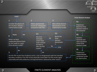
FINITE ELEMENT ANALYSIS
BY ; SYED ABDULLA ZAIN
© Syed Abdulla Zain
FINITE ELEMENT ANALYSIS
TRADITIONAL DESIGN PROCESS
➢ DESIGN ( CAD)
➢ VIRTUAL TEST
➢ BUILD
➢ TEST
FINITE ELEMENT ANALYSIS
METHODS TO SOLVE ENGINEERING PROBLEMS
➢ Analytical Method
➢ Numerical Method
➢ Experimental Method
FINITE ELEMENT ANALYSIS
ANALYTICAL METHOD
➢ Classical approach
➢ 100% Accurate results
➢ Applicable only for simple problems
FINITE ELEMENT ANALYSIS
NUMERICAL METHOD
➢ Mathematical representation
➢ Approximate , assumptions are made
➢ Real life complex problems
➢ Results cannot be believed blindly. Certain results must be
validated by experiments and or analytical method
FINITE ELEMENT ANALYSIS
NUMERICAL METHOD
➢ Finite element method
➢ Boundry element method
➢ Finite volume method
➢ Finite difference method
FINITE ELEMENT ANALYSIS
EXPERIMENTAL METHOD
➢ Actual measurement
➢ Time consuming & need expensive set up
➢ Applicable only when physical prototype is available
➢ Results cannot be believed blindly
➢ A minimum of 3 to 5 prototypes must be tested
FINITE ELEMENT ANALYSIS
PROCEDURE FOR SOLVING ANALYTICAL/ NUMERICAL
METHOD
➢ Writing of the governing equations
➢ Mathematical solution of governing equations
FINITE ELEMENT ANALYSIS
INTRODUCTION TO DIFFERENT NUMERICAL METHOD
➢ FINITE ELEMENT METHOD
FEM is the most popular Numerical method
FEM is a numerical technique used to determine the
approximate solution for a PDE on a defined domain
FINITE ELEMENT ANALYSIS
INTRODUCTION TO DIFFERENT NUMERICAL METHOD
➢ BOUNDRY ELEMENT METHOD
This is a very powerful and efficient technique to solve acoustics
or NVH problems
Boundry element method is a numerical method of solving
linear PDE which have been formulated as integral equations
FINITE ELEMENT ANALYSIS
INTRODUCTION TO DIFFERENT NUMERICAL METHOD
➢ FINITE VOLUME METHOD
The FVM is a method for representing and evaluating partial
differential equations as algebraic equations
FINITE ELEMENT ANALYSIS
INTRODUCTION TO DIFFERENT NUMERICAL METHOD
➢ FINITE DIFFERENCE METHOD
The FDM is described as a way to solve differential equation. It
uses taylor series to convert a differential equation to an
algebraic equation
FINITE ELEMENT ANALYSIS
ADVANTAGES OF FEA
➢ Visualization increases
➢ Design cycle time decreases
➢ No of prototypes decreases
➢ Testing decreases
➢ Optimum design
FINITE ELEMENT ANALYSIS
STIFFNESS MATRIX METHODS
➢ Direct Method
➢ Variational method
➢ Weighted residual method
FINITE ELEMENT ANALYSIS
STEPS INVOLVED IN FEA
Step 1 - Discretization: The problem domain is discretized into a
collection of simple shapes, or elements.
Step 2 - Develop Element Equations: Developed using the
physics of the problem, and typically Galerkin’s Method or
variational principles.
Step 3 - Assembly: The element equations for each element in
the FEM mesh are assembled into a set of global equations that
model the properties of the entire system.
FINITE ELEMENT ANALYSIS
STEPS INVOLVED IN FEA
Step 4 - Application of Boundary Conditions: Solution cannot be
obtained unless boundary conditions are applied. They reflect
the known values for certain primary unknowns. Imposing the
boundary conditions modifies the global equations.
Step 5 - Solve for Primary Unknowns: The modified global
equations are solved for the primary unknowns at the nodes.
Step 6 - Calculate Derived Variables: Calculated using the nodal
values of the primary variables
FINITE ELEMENT ANALYSIS
STEPS INVOLVED IN FEA
➢ Modeling or Preprocessing
➢ Solution or Analysis
➢ Visualization or post processing
FINITE ELEMENT ANALYSIS
MODELLING OR PRE PROCESSING
➢ Import of CAD
➢ Meshing
➢ Material and property information
➢ Loads constraints and solver information
FINITE ELEMENT ANALYSIS
A
A
A
B
B
A
B
C
A
C
AB
C
D
A
B
D
C
A
E
D
B
C
E
F
D
A
B
E
C
F
D
E
C
G
D
F
E
G
C
D
B
A
D
H
E
F
G
E
C
F
D
B
H
A
E
G
D
D
H
F
E
D
C
G
C
B
F
G
C
E
B
A
D
F
B
C
E
A
D
BC
E
A
D
A
B
C
BD
A
C
A
B
A
A
B
C
AB
X
Y
Z
FINITE ELEMENT ANALYSIS
Consider the physics of
the situation. Devise a
mathematical model.
Obtain approximate
results for subsequent
comparison with FEA.
Plan a finite element
discretization of the
mathematical model.
Preprocess:
Build the finite
element model in
the computer.
Solution:
Generate and
solve equations
of the finite
element model.
Postprocess:
Output/display
computed results
for examination.
Are the FEA results free of obvious errors, such as disagreement with the intended
boundary conditions? Are FEA results physically reasonable? Do FEA results agree
reasonably well with predictions and approximations obtained by other means?
What is at fault,
Inadequate physical basis
for the model or a poor
finite element model?
Are error
estimates
small? Does
mesh revision
do little to
alter the FEA
results?
Revise the
finite
element
discretizatio
n
STOP
START
Physics FEA
No
Yes
Yes
No
Finite Element Analysis
1 2 3 4a
5
4b
4c
D1
H
D2
FINITE ELEMENT ANALYSIS
SOLIDWORKS SIMULATION
Dassault Systems
3 – D and PLM software
➢ Building models on Computer
➢ Engineering Analysis and Design
➢ Production
➢ Market.
FINITE ELEMENT ANALYSIS
➢ SOLIDWORKS
3D CAD : Creating complex parts and assemblies
Modeling tools : Feature Recognition, Reverse Engineering
Simulation: Engineering Analysis tools for structural,
fluid and thermal analysis.
2D Drawings : Working drawings for production
Data Management
Presentation : Photoworks
FINITE ELEMENT ANALYSIS
INTRODUCTION TO SOLIDWORKS SIMULATION
➢ SolidWorks Simulation is a design analysis software that is
fully integrated in SolidWorks.
➢ SolidWorks Simulation simulates the testing of your model’s
prototype in its working environment. It can help you answer
questions like: how safe, efficient, and economical is your
design?
➢ SolidWorks Simulation is used by students, designers,
analysts, engineers, and other professionals to produce safe,
efficient, and economical designs.
FINITE ELEMENT ANALYSIS
ANALYSIS TYPES
CAE includes the following types of analysis
➢ Linear static analysis Crash analysis
➢ Non linear analysis NVH analysis
➢ Dynamic analysis
➢ Buckling analysis
➢ Thermal analysis
➢ Fatigue analysis
➢ Optimization
➢ CFD analysis
FINITE ELEMENT ANALYSIS
LINEAR STATIC ANALYSIS
➢ In linear analysis the FE solver will therefore always follow a
straight line from base to deformed shape
FINITE ELEMENT ANALYSIS
NONLINEAR ANALYSIS
➢ Non linear analysis deals with the true stress and strain
A non linear analysis is performed when we need to consider
➢ Material based non linearity
➢ Geometric non linearity
➢ Contact or boundary non linearity
FINITE ELEMENT ANALYSIS
DYNAMIC ANALYSIS
➢ Linear dynamics
➢ Non linear dynamics
FINITE ELEMENT ANALYSIS
LINEAR BUCKLING ANALYSIS
➢ Applicable for only compressive loads
➢ Slender beams and sheet metal parts
FINITE ELEMENT ANALYSIS
THERMAL ANALYSIS
➢ Heat transfer analysis solve for the unknown temperatures
and fluxes under thermal loading.
FINITE ELEMENT ANALYSIS
➢ FATIGUE ANALYSIS
➢ OPTIMIZATION
FINITE ELEMENT ANALYSIS
COMPUTATIONAL FLUID DYNAMICS
➢ Fluid statics
➢ Fluid dynamics
Computational fluid dynamics is the branch of fluid mechanics
where numerical methods are used to analyze fluid dynamics
problems
FINITE ELEMENT ANALYSIS
FLOW CLASSIFICATION
➢ Viscosity
➢ Dimensions
➢ Turbulent or laminar
➢ Compressibility
➢ Velocity
FINITE ELEMENT ANALYSIS
CRASH ANALYSIS
➢ Structural crash worthiness or full dynamic or impact
simulations
➢ Drop test simulations
➢ occupant safety
FINITE ELEMENT ANALYSIS
NOICE VIBRATION & HARSHNESS
➢ Sound radiation or scattering or uncoupled problems
➢ Coupled or vibroacoustics problems
Introduction to Finite Element Method

Introduction to Finite Element Method

  • 1.
    FINITE ELEMENT ANALYSIS BY; SYED ABDULLA ZAIN © Syed Abdulla Zain
  • 2.
    FINITE ELEMENT ANALYSIS TRADITIONALDESIGN PROCESS ➢ DESIGN ( CAD) ➢ VIRTUAL TEST ➢ BUILD ➢ TEST
  • 3.
    FINITE ELEMENT ANALYSIS METHODSTO SOLVE ENGINEERING PROBLEMS ➢ Analytical Method ➢ Numerical Method ➢ Experimental Method
  • 4.
    FINITE ELEMENT ANALYSIS ANALYTICALMETHOD ➢ Classical approach ➢ 100% Accurate results ➢ Applicable only for simple problems
  • 5.
    FINITE ELEMENT ANALYSIS NUMERICALMETHOD ➢ Mathematical representation ➢ Approximate , assumptions are made ➢ Real life complex problems ➢ Results cannot be believed blindly. Certain results must be validated by experiments and or analytical method
  • 6.
    FINITE ELEMENT ANALYSIS NUMERICALMETHOD ➢ Finite element method ➢ Boundry element method ➢ Finite volume method ➢ Finite difference method
  • 7.
    FINITE ELEMENT ANALYSIS EXPERIMENTALMETHOD ➢ Actual measurement ➢ Time consuming & need expensive set up ➢ Applicable only when physical prototype is available ➢ Results cannot be believed blindly ➢ A minimum of 3 to 5 prototypes must be tested
  • 8.
    FINITE ELEMENT ANALYSIS PROCEDUREFOR SOLVING ANALYTICAL/ NUMERICAL METHOD ➢ Writing of the governing equations ➢ Mathematical solution of governing equations
  • 9.
    FINITE ELEMENT ANALYSIS INTRODUCTIONTO DIFFERENT NUMERICAL METHOD ➢ FINITE ELEMENT METHOD FEM is the most popular Numerical method FEM is a numerical technique used to determine the approximate solution for a PDE on a defined domain
  • 10.
    FINITE ELEMENT ANALYSIS INTRODUCTIONTO DIFFERENT NUMERICAL METHOD ➢ BOUNDRY ELEMENT METHOD This is a very powerful and efficient technique to solve acoustics or NVH problems Boundry element method is a numerical method of solving linear PDE which have been formulated as integral equations
  • 11.
    FINITE ELEMENT ANALYSIS INTRODUCTIONTO DIFFERENT NUMERICAL METHOD ➢ FINITE VOLUME METHOD The FVM is a method for representing and evaluating partial differential equations as algebraic equations
  • 12.
    FINITE ELEMENT ANALYSIS INTRODUCTIONTO DIFFERENT NUMERICAL METHOD ➢ FINITE DIFFERENCE METHOD The FDM is described as a way to solve differential equation. It uses taylor series to convert a differential equation to an algebraic equation
  • 13.
    FINITE ELEMENT ANALYSIS ADVANTAGESOF FEA ➢ Visualization increases ➢ Design cycle time decreases ➢ No of prototypes decreases ➢ Testing decreases ➢ Optimum design
  • 14.
    FINITE ELEMENT ANALYSIS STIFFNESSMATRIX METHODS ➢ Direct Method ➢ Variational method ➢ Weighted residual method
  • 15.
    FINITE ELEMENT ANALYSIS STEPSINVOLVED IN FEA Step 1 - Discretization: The problem domain is discretized into a collection of simple shapes, or elements. Step 2 - Develop Element Equations: Developed using the physics of the problem, and typically Galerkin’s Method or variational principles. Step 3 - Assembly: The element equations for each element in the FEM mesh are assembled into a set of global equations that model the properties of the entire system.
  • 16.
    FINITE ELEMENT ANALYSIS STEPSINVOLVED IN FEA Step 4 - Application of Boundary Conditions: Solution cannot be obtained unless boundary conditions are applied. They reflect the known values for certain primary unknowns. Imposing the boundary conditions modifies the global equations. Step 5 - Solve for Primary Unknowns: The modified global equations are solved for the primary unknowns at the nodes. Step 6 - Calculate Derived Variables: Calculated using the nodal values of the primary variables
  • 17.
    FINITE ELEMENT ANALYSIS STEPSINVOLVED IN FEA ➢ Modeling or Preprocessing ➢ Solution or Analysis ➢ Visualization or post processing
  • 18.
    FINITE ELEMENT ANALYSIS MODELLINGOR PRE PROCESSING ➢ Import of CAD ➢ Meshing ➢ Material and property information ➢ Loads constraints and solver information
  • 19.
  • 20.
    FINITE ELEMENT ANALYSIS Considerthe physics of the situation. Devise a mathematical model. Obtain approximate results for subsequent comparison with FEA. Plan a finite element discretization of the mathematical model. Preprocess: Build the finite element model in the computer. Solution: Generate and solve equations of the finite element model. Postprocess: Output/display computed results for examination. Are the FEA results free of obvious errors, such as disagreement with the intended boundary conditions? Are FEA results physically reasonable? Do FEA results agree reasonably well with predictions and approximations obtained by other means? What is at fault, Inadequate physical basis for the model or a poor finite element model? Are error estimates small? Does mesh revision do little to alter the FEA results? Revise the finite element discretizatio n STOP START Physics FEA No Yes Yes No Finite Element Analysis 1 2 3 4a 5 4b 4c D1 H D2
  • 21.
    FINITE ELEMENT ANALYSIS SOLIDWORKSSIMULATION Dassault Systems 3 – D and PLM software ➢ Building models on Computer ➢ Engineering Analysis and Design ➢ Production ➢ Market.
  • 22.
    FINITE ELEMENT ANALYSIS ➢SOLIDWORKS 3D CAD : Creating complex parts and assemblies Modeling tools : Feature Recognition, Reverse Engineering Simulation: Engineering Analysis tools for structural, fluid and thermal analysis. 2D Drawings : Working drawings for production Data Management Presentation : Photoworks
  • 23.
    FINITE ELEMENT ANALYSIS INTRODUCTIONTO SOLIDWORKS SIMULATION ➢ SolidWorks Simulation is a design analysis software that is fully integrated in SolidWorks. ➢ SolidWorks Simulation simulates the testing of your model’s prototype in its working environment. It can help you answer questions like: how safe, efficient, and economical is your design? ➢ SolidWorks Simulation is used by students, designers, analysts, engineers, and other professionals to produce safe, efficient, and economical designs.
  • 24.
    FINITE ELEMENT ANALYSIS ANALYSISTYPES CAE includes the following types of analysis ➢ Linear static analysis Crash analysis ➢ Non linear analysis NVH analysis ➢ Dynamic analysis ➢ Buckling analysis ➢ Thermal analysis ➢ Fatigue analysis ➢ Optimization ➢ CFD analysis
  • 25.
    FINITE ELEMENT ANALYSIS LINEARSTATIC ANALYSIS ➢ In linear analysis the FE solver will therefore always follow a straight line from base to deformed shape
  • 26.
    FINITE ELEMENT ANALYSIS NONLINEARANALYSIS ➢ Non linear analysis deals with the true stress and strain A non linear analysis is performed when we need to consider ➢ Material based non linearity ➢ Geometric non linearity ➢ Contact or boundary non linearity
  • 27.
    FINITE ELEMENT ANALYSIS DYNAMICANALYSIS ➢ Linear dynamics ➢ Non linear dynamics
  • 28.
    FINITE ELEMENT ANALYSIS LINEARBUCKLING ANALYSIS ➢ Applicable for only compressive loads ➢ Slender beams and sheet metal parts
  • 29.
    FINITE ELEMENT ANALYSIS THERMALANALYSIS ➢ Heat transfer analysis solve for the unknown temperatures and fluxes under thermal loading.
  • 30.
    FINITE ELEMENT ANALYSIS ➢FATIGUE ANALYSIS ➢ OPTIMIZATION
  • 31.
    FINITE ELEMENT ANALYSIS COMPUTATIONALFLUID DYNAMICS ➢ Fluid statics ➢ Fluid dynamics Computational fluid dynamics is the branch of fluid mechanics where numerical methods are used to analyze fluid dynamics problems
  • 32.
    FINITE ELEMENT ANALYSIS FLOWCLASSIFICATION ➢ Viscosity ➢ Dimensions ➢ Turbulent or laminar ➢ Compressibility ➢ Velocity
  • 33.
    FINITE ELEMENT ANALYSIS CRASHANALYSIS ➢ Structural crash worthiness or full dynamic or impact simulations ➢ Drop test simulations ➢ occupant safety
  • 34.
    FINITE ELEMENT ANALYSIS NOICEVIBRATION & HARSHNESS ➢ Sound radiation or scattering or uncoupled problems ➢ Coupled or vibroacoustics problems