Download as PDF, PPTX

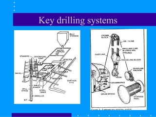
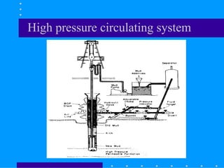
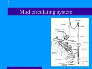
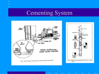
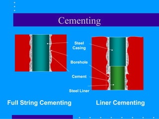

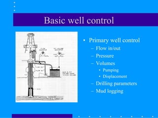
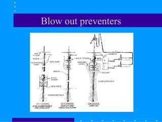
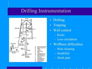
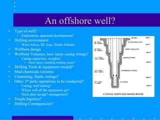
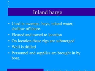
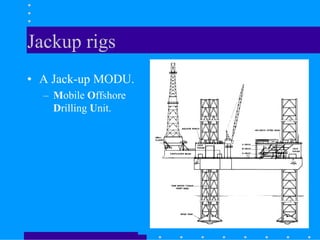
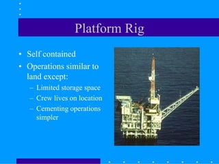
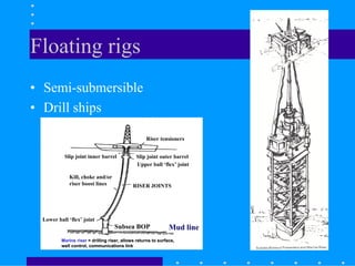
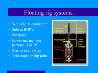
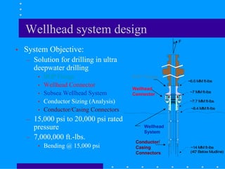
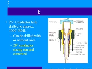
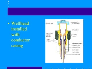
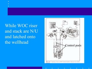
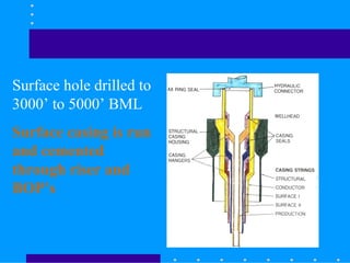
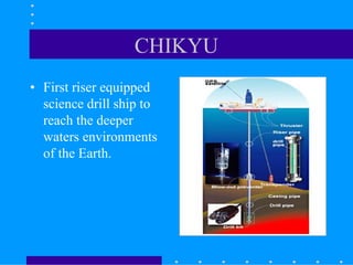
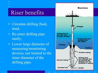
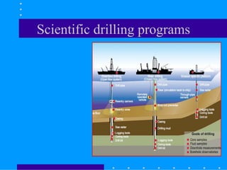
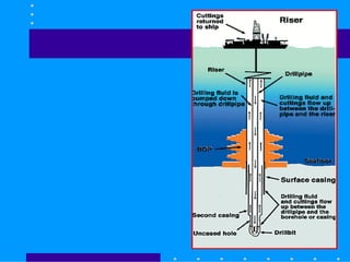
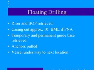

This document discusses various types of offshore drilling rigs and operations. It describes inland barges, jackup rigs, platform rigs, and floating rigs like semi-submersibles and drillships. The key systems involved in offshore drilling are also summarized, including well design, mud systems, cementing, blowout preventers, and riser systems. Offshore drilling processes like running casing and conductor pipes are also outlined.


![[4] ptk 2014 2015 offshore constructions](https://cdn.slidesharecdn.com/ss_thumbnails/mhu59qizqiwfpndume0q-signature-e54dc48fc8dff231a3667ed370712382aa80c6605f7be8d156fba02fb451e6f5-poli-141027141817-conversion-gate01-thumbnail.jpg?width=640&height=640&fit=bounds)


