Downloaded 348 times
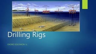

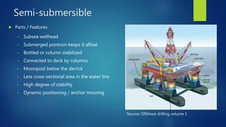

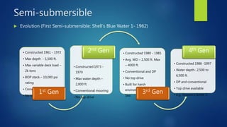


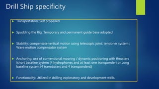


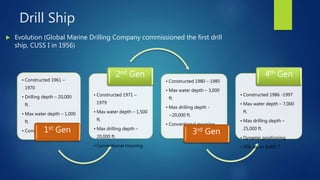

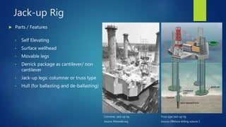
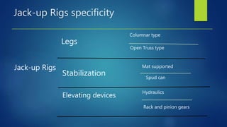


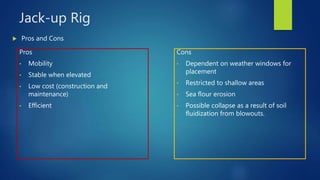
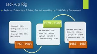
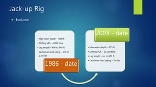
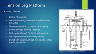

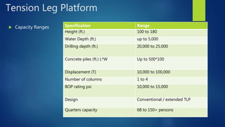

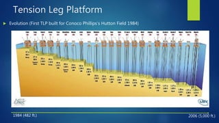
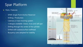


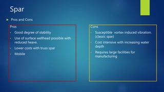
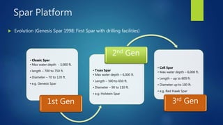


This document provides information about various types of offshore drilling rigs, including their key components, specifications, evolution over generations, and advantages and disadvantages. It describes semi-submersible rigs, drill ships, jack-up rigs, and tension leg platforms. For each type, it outlines the main parts, capacity ranges, pros and cons, and how the rigs have advanced technologically from earlier to later generations to enable drilling in deeper waters.


