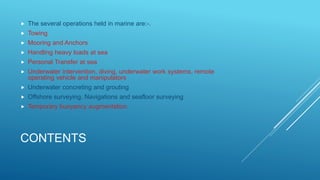
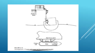
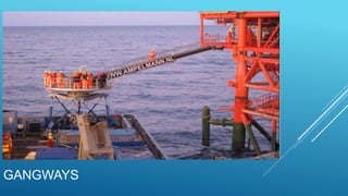
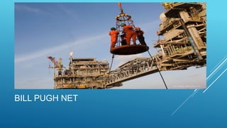
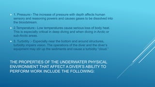
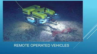
MARINE OPERATIONS
By Varun.Y.S (MT15CTM018)
VNIT, Nagpur
CONTENTS
 The several operations held in marine are:-.
 Towing
 Mooring and Anchors
 Handling heavy loads at sea
 Personal Transfer at sea
 Underwater intervention, diving, underwater work systems, remote
operating vehicle and manipulators
 Underwater concreting and grouting
 Offshore surveying, Navigations and seafloor surveying
 Temporary buoyancy augmentation.
TOWING
 Towing is coupling two or more objects together so that they may be
pulled by a designated power source or sources.
 General arrangements for towing is as shown in the figure
GENERAL ARRANGEMENTS
POINTS TO BE NOTED
 Attachments should be sufficiently strong to pull.
 The actual breaking strength of wire rope is typically 10%–15% greater
than the guaranteed minimum breaking strength. Actual breakage will
usually occur under a dynamic load rather than a static load.
 If a towline does break at sea, it is desirable that it fail at a known “weak
link” so that it may readily be reconnected, even in high sea states.
TO CONTROL IF BREAKAGE
 When towing in thin or broken ice, an icebreaking vessel will usually
open a clear channel.
 When positioning a structure at an offshore site, it
is customary for the tugs to fan out in star fashion.
Then, the positioning is controlled by going ahead
on some tugs more than others; that is, all lines are
kept taut.
LIMITATIONS AND REQUIREMENTS ARE PLACED ON
STABILITY UNDER TOW BY THE MARINE SURVEYOR.
TYPICAL REQUIREMENTS ARE THE FOLLOWING:
 The metacentric height should have a positive value, typically 1–2 m for a
large offshore structure.
 The maximum inclination of the towed structure under conditions of HsZ5
m, wind 60 km/h, and full towline pull is not to exceed 5°.
 The static inclination under half the total towline pull, in still water, does not
exceed 2°.
 The static range of stability should not be less than 158 at the draft during
tow or installation.
 Inclining tests to verify the GM (metacentric height) must be carried out
shortly before the tow, after all superstructure modules and consumables
have been loaded.
MOORING AND ANCHORS
 Vessels working at an offshore site must be held in position despite the
effects of wind, waves, and current.
 The standard means of mooring is by way of a mooring system that
connects the vessel(or structure) to the seafloor by means of laterally
leading lines to anchors.
 Moorings must be thought of as a system that includes the vessel, the
anchor engines, fairleads, mooring lines, buoys, and anchor.
MOORING LINES
 Very low modulus material like Nylon is widely used for very short lines;
unfortunately, it is so elastic that it stores great amounts of energy. If a
nylon line breaks, it may not only develop a sudden shock loading but
whip back dangerously
 Higher-modulus fiber lines, such as Kevlar, are available.
 Steel wire rope is the standard material for mooring lines for
construction.
ANCHORS
DRAG ANCHORS
 These anchors are designed so that, as a horizontal force
is applied, they dig down into the soil and mobilize it as
resisting force.
 Drag embedment anchors are ineffective on rock and
erratic on layered (stratified) seafloors. So for these
conditions, a clump or gravity anchor is used. These
develop their resistance primarily from dead weight times a
friction factor.
PILE ANCHORS
 The pile can either be drilled in and grouted, using an offshore mobile
drilling rig, or driven in with an underwater hammer or a follower.
 Of special concern are soils that have unsuitable characteristics. One of
these is calcareous soil, for which little skin friction is developed. Any
vertical force applied will lift the pile. Even a straight horizontal force
may lead to crushing of the calcareous grains and a degradation of
holding power. Extensive grouting of an anchor pile in such soils has
greatly improved its capacity as compared with a driven anchor pile.
PROPELLANT ANCHORS
 The anchor shaft is driven into the soil by either free fall or explosive
force. Once penetrated, its flukes resist pullout.
 These anchors are multidirectional, are installed rapidly, and function
best where drag anchors are least effective.
 For use in the deep sea (over 200 m), the anchors must resist primarily
vertical forces. Very heavy concrete deadweight anchors may be used.
 Recent development includes drag anchors shaped to develop high
vertical capacity. They are seated by horizontal pull, then rotated (or the
flukes rotate) to resist uplift.
SUCTION ANCHORS
 Suction anchors gain their vertical capacity by the weight of the plug
inside and the friction (shear) on the outer surfaces, and in addition, the
negative end-bearing, that is, the force required to sepa
 Typically, suction anchors are larger than 5 m in diameter and 20–30 m
in length.
 The suction anchor is lowered to the seafloor with the top valve open
and allowed to penetrate under its own dead weight. Then the top
valves are closed and water pumped out to create an under pressure in
the cylinder.
 For removal, the water is forced into the top of the anchor
DRIVEN PLATE ANCHORS
 A flat plate is connected to the lower end of a steel pile with a stout
hinge, and a shot of chain is attached. Then the pile is driven into the
seafloor, the steel plate in a vertical alignment being pulled down deep
in the soil. When the lateral pull is taken on the chain, the plate rotates
as it pulls upward and develops the full weight and shear resistance of
the soil above
HANDLING HEAVY LOADS AT SEA
 The installation of marine structures usually includes the lifting and
setting of modules and other heavy loads on the platform.
 Loads up to 13,000 tn. have been set by derrick barges with two cranes
 The hammerhead crane has been successfully employed to erect piers,
shafts, and girders up to 8000 tn.
 For the 24,000-tn. prefabricated piers of the Storm Surge Barrier,
12,000 tn. was supplied by buoyancy and 12,000 tn. by a catamaran lift
barge.
HANDLING HEAVY LOADS AT SEA
 When lifting a heavy load, there are both static and dynamic forces to
consider.
 Static loads includes self weight and others
 The dynamic forces are those due to acceleration, first as the load line
lifts while the load, still resting on the barge, is starting the down-heave
cycle. Later, both horizontal and vertical accelerations are imposed
during swing. Lifting forces on the padeyes and the structural members
of the load to which they are secured have both vertical and horizontal
components.
HANDLING LOADS AT SEA
 Vertical forces on lifting can include the favourable effects of buoyancy
where applicable; however, fully or partially submerged structures may
pick up an added hydrodynamic mass component. This latter may be a
very high factor when the submerged surface is horizontal
HANDLING HEAVY LOADS AT SEA
 Instrumentation is now available to enable control of the dynamic aspects of lifting. These
consist of sensors on the crane barge, on the crane boom, and on the barge or boat from
which the module or other lift is being lifted.
 Typically, mini- or microcomputers then give readouts of load on hook,
 out-reach (radius),
 hook height,
 wave height,
 wave period,
 hook speed,
 crane hook height, off-lead (distance between load and fixed structure), automatic level luffing,
and warning as to turns remaining on winch drum. Other programs are available to determine
optimum heading of crane barge to minimize boom tip motion and hence, the dynamic
increment of load during the operation.
HOOKS
PERSONNEL TRANSFER AT SEA
 The transfer of personnel from crew boat to offshore derrick
barge or onto a fixed platform is a critical operation from the
point of view of both safety and efficiency.
 This operation is overlooked in the planning phase.
 The boat in which the personnel are traveling to the
offshore rig is responding to the wave action in all modes,
heave, pitch, and roll being the most critical for the transfer
operation.
PERSONNEL TRANSFER AT SEA
 The use of fixed inclined “ladders” is not safe; instead articulated ladders can be used.
 Cargo nets is hung from a boom, so that the lower end is at sea level; when the boat moors,
the net can be hauled into the boat.
 It is a relatively simple and safe operation for people to catch the top of the heave-pitch cycle
and climb up the net.
 When they reach the boom, however, they face a dilemma. Somehow they are expected to
scramble onto the boom and walk in to the deck.
PERSONNEL TRANSFER AT SEA
 Transfer back from platform to boat is more difficult
 Assuming lifelines make it easy to get onto the net and climb down,
below is a boat moving up and down in a 5- to 7-s period.
 the net should be placed in the well of the boat, about midships, rather
than at the bow. Then relative motions will be minimized
 For more severe sea states, the Billy Pugh net is employed.
 Helicopters are today used for long-distance personnel transfer,
especially where rough seas are frequently encountered.
GANGWAYS
BILL PUGH NET
UNDERWATER INTERVENTION, DIVING,
UNDERWATER WORK SYSTEMS,
REMOTE-OPERATED VEHICLES (ROVS), AND
MANIPULATORS
DIVING
TASKS THAT DIVERS MAY BE CALLED
UPON TO PERFORM.
 1. Inspection and NDT
 a. Magnetic particle inspection equipment
 b. Ultrasonic equipment
 c. Eddy current/electromagnetic equipment
 d. Radiation monitors, trace leak detectors
 e. Cathodic protection monitoring equipment
 f. Range-level measuring and positioning equipment
 g. Metal detectors
 h. Thermometers
TASKS THAT DIVERS MAY BE CALLED
UPON TO PERFORM.
 2. Photographic equipment
 a. Still cameras
 b. Cine (movie) cameras
 c. Video systems (TV cameras)
 3. Underwater cleaning equipment
 a. Water jetting and grit blasting
 b. Portable brush-cleaning machines
 c. Self-propelled cleaning machines
TASKS THAT DIVERS MAY BE CALLED
UPON TO PERFORM.
 4. Torqueing and tensioning equipment
 a. Manual and hydraulic torque wrenches
 b. Torque multipliers
 c. Stud tensioners
 d. Extensometers
 e. Flange pulling–splitting tools
 5. Lifting equipment and holdfasts
 a. Lifting-inflatable bags
 b. Gas generators
 c. Lifting–pulling machines
 d. Magnetic handles and suction pads
TASKS THAT DIVERS MAY BE CALLED
UPON TO PERFORM.
 6. General underwater equipment
 a. Wet welding habitats and equipment
 b. Underwater machining tools
 c. Chipping hammers
 d. Cutoff saws
 e. Grinders
 f. Drills
 g. Impact wrenches
 h. Hydraulic wire cutters, cable crimpers, spreaders
 i. Hydraulic fracture-initiators and breakers
 j. Power-actuated fasteners, cutters
TASKS THAT DIVERS MAY BE CALLED
UPON TO PERFORM.
 k. Pressure intensifiers
 l. Grouting and resin injectors and dispensers
 m. Underwater painting machines
 n. Jet pump dredges, airlifts, and ejectors
 o. Subsea marking systems
 p. Abrasive and mechanical cutting equipment
TASKS THAT DIVERS MAY BE CALLED
UPON TO PERFORM.
 7. Subsea power packs
 8. Diver-held location devices
 a. Cable tracking system
 9. Explosive devices
 a. Pipe, chain and, casing cutters
 b. Perforators
 c. Shaped charges
 d. Underwater rock drills
TASKS THAT DIVERS MAY BE CALLED
UPON TO PERFORM.
 10. Underwater lighting
 11. Chain blocks
 12. Jet burning equipment—thermic lancers
 13. Diver-operated geotechnical tools
 a. Impact corer
 b. Miniature standard penetration test tool
 c. Vane shear
 d. Rock classifier
 e. Jet probe
 f. Vacuum corer
THE PROPERTIES OF THE UNDERWATER PHYSICAL
ENVIRONMENT THAT AFFECT A DIVER’S ABILITY TO
PERFORM WORK INCLUDE THE FOLLOWING:
 1. Pressure:- The increase of pressure with depth affects human
sensory and reasoning powers and causes gases to be dissolved into
the bloodstream.
 2.Temperature:- Low temperatures cause serious loss of body heat.
This is especially critical in deep diving and when diving in Arctic or
sub-Arctic areas.
 3. Turbidity :- Especially near the bottom and around structures,
turbidity impairs vision. The operations of the diver and the diver’s
equipment may stir up the sediments and cause a turbidity “cloud.”
THE PROPERTIES OF THE UNDERWATER PHYSICAL
ENVIRONMENT THAT AFFECT A DIVER’S ABILITY TO
PERFORM WORK INCLUDE THE FOLLOWING:
 4. Currents:- Currents tend to sweep the diver away from location and to
make the diver’s position control more difficult.
 5. Refraction phenomena:- Underwater refraction of light and acoustic
waves is different from those in air.
 6. Waves:- Waves endanger the descent and ascent of the diver through
the sea–air interface.
 7. Marine growth:- These shield surfaces and joints from inspection and
can rip a diver’s suit.
 8. Buoyancy:-Since the diver’s underwater weight is only marginally
negative, the diver cannot exert a significant thrust from the body.
TOOLS AND PROCEDURES HAVE BEEN DEVELOPED TO
ENABLE DIVERS TO WORK EFFECTIVELY
UNDERWATER
 Wet welding techniques
 Dry welding
 Underwater cutting using electric arc method
 Mechanical casing cutter and abrasive jet cutters
 hydraulically driven velocity power (explosively driven) tools
REMOTE OPERATED VEHICLES
REMOTE OPERATED VEHICLE
 An ROV may embody the following equipment and capabilities:
 Strobe light;
 High-resolution TV video;
 Low-light-level black-and-white photography
 Stereo photogrammetry;
 Multibeam SWATH and side-scan sonar, acoustic imaging;
 Manipulators for turning bolts and nuts and for grasping;
 Inertial guidance, acoustic navigation;
 Corrosion potential probes;
REMOTE OPERATED VEHICLES
 Cleaning and grinding tools;
 Pinger dropper;
 Installation of fittings;
 Buoyancy modules;
 Attachment of lines and object retrieval;
 Wire rope cutter;
 Hydraulically operated tools such as cutters, drills, and jacks;
 Thrusters.
REMOTE OPERATED VEHICLES
 ROVs are invaluable for deep-water installations since they are not
depth limited. Upto 2500 and deeper
 ROVs are especially well suited for survey and inspection of structures
during installation and while in service.
 Because of the efficiency of ROVs for underwater intervention, their use
is growing rapidly. They are gradually taking over many of the functions,
such as inspection of pipelines, formerly performed by divers.
MANIPULATORS
 Another approach to carrying out operations underwater is utilization of
special-purpose devices, which are guided to a specific location by wire
lines or rails.
UNDERWATER CONCRETING AND
GROUTING
 UNDERWATEE CONCRETE MIXES
 Underwater concrete should be proportioned to develop a plastic, highly
workable, and cohesive mix, not subject to segregation.
 Coarse aggregate: Gravel of 20 mm(3/4 in.)maximum size. Use 50%–55%
of the total aggregate by weight. For congested areas, use 10 mm
maximum size aggregate.
 Fine aggregate: Sand, 45%–50% of the total aggregate by weight.
 Cement: Type II ASTM, 350 kg/m3.
 Fly ash: ASTM 616 Type N, F, or C: 60 kg/m3.
 Total cementitious materials: 350–475 kg/m3
UNDERWATER CONCRETING AND
GROUTING
 Water: (w/cm), 0.37–0.42
 Water-reducing admixture: WRA or HRWRA (super-plasticizer):
 Retarding admixture: as required to give desired initial and final set.
 Slump: about 200 mm.
 Admixtures to reduce bleed and to provide viscosity.
 fly ash being 20%–30%. Fly ash retards set.
UNDERWATER CONCRETING AND
GROUTING
 Silica fume in proportions of 4%–6% may be added. Mixing procedures
and adequate time of mixing are essential to give adequate dispersal of
densified silica fume. Fly ash should always be used with silica fume.
Silica fume increases both early and long term strength.
TEMPORARY BUOYANCY
AUGMENTATION
 1. Reducing draft during float out from a construction basin and during tow
 2. Giving flotation to a pipeline or reducing its net weight in water
 3. Reducing weights of structures or elements during installation or salvage
 4. Changing the lead of towlines which have been attached below water
 5. Providing stability to a structure during deck mating or installation
 6. Providing control of draft and attitude during float out, tow, launching,
installation, and/or removal.
THANK YOU
They that go down to the sea in ships, that do business on
the great waters, these see the works of the Lord and His
wonders of the deep

Marine operations

  • 1.
    MARINE OPERATIONS By Varun.Y.S(MT15CTM018) VNIT, Nagpur
  • 2.
    CONTENTS  The severaloperations held in marine are:-.  Towing  Mooring and Anchors  Handling heavy loads at sea  Personal Transfer at sea  Underwater intervention, diving, underwater work systems, remote operating vehicle and manipulators  Underwater concreting and grouting  Offshore surveying, Navigations and seafloor surveying  Temporary buoyancy augmentation.
  • 3.
    TOWING  Towing iscoupling two or more objects together so that they may be pulled by a designated power source or sources.  General arrangements for towing is as shown in the figure
  • 4.
  • 5.
    POINTS TO BENOTED  Attachments should be sufficiently strong to pull.  The actual breaking strength of wire rope is typically 10%–15% greater than the guaranteed minimum breaking strength. Actual breakage will usually occur under a dynamic load rather than a static load.  If a towline does break at sea, it is desirable that it fail at a known “weak link” so that it may readily be reconnected, even in high sea states.
  • 6.
    TO CONTROL IFBREAKAGE
  • 7.
     When towingin thin or broken ice, an icebreaking vessel will usually open a clear channel.
  • 8.
     When positioninga structure at an offshore site, it is customary for the tugs to fan out in star fashion. Then, the positioning is controlled by going ahead on some tugs more than others; that is, all lines are kept taut.
  • 9.
    LIMITATIONS AND REQUIREMENTSARE PLACED ON STABILITY UNDER TOW BY THE MARINE SURVEYOR. TYPICAL REQUIREMENTS ARE THE FOLLOWING:  The metacentric height should have a positive value, typically 1–2 m for a large offshore structure.  The maximum inclination of the towed structure under conditions of HsZ5 m, wind 60 km/h, and full towline pull is not to exceed 5°.  The static inclination under half the total towline pull, in still water, does not exceed 2°.  The static range of stability should not be less than 158 at the draft during tow or installation.  Inclining tests to verify the GM (metacentric height) must be carried out shortly before the tow, after all superstructure modules and consumables have been loaded.
  • 10.
    MOORING AND ANCHORS Vessels working at an offshore site must be held in position despite the effects of wind, waves, and current.  The standard means of mooring is by way of a mooring system that connects the vessel(or structure) to the seafloor by means of laterally leading lines to anchors.  Moorings must be thought of as a system that includes the vessel, the anchor engines, fairleads, mooring lines, buoys, and anchor.
  • 11.
    MOORING LINES  Verylow modulus material like Nylon is widely used for very short lines; unfortunately, it is so elastic that it stores great amounts of energy. If a nylon line breaks, it may not only develop a sudden shock loading but whip back dangerously  Higher-modulus fiber lines, such as Kevlar, are available.  Steel wire rope is the standard material for mooring lines for construction.
  • 12.
    ANCHORS DRAG ANCHORS  Theseanchors are designed so that, as a horizontal force is applied, they dig down into the soil and mobilize it as resisting force.  Drag embedment anchors are ineffective on rock and erratic on layered (stratified) seafloors. So for these conditions, a clump or gravity anchor is used. These develop their resistance primarily from dead weight times a friction factor.
  • 14.
    PILE ANCHORS  Thepile can either be drilled in and grouted, using an offshore mobile drilling rig, or driven in with an underwater hammer or a follower.  Of special concern are soils that have unsuitable characteristics. One of these is calcareous soil, for which little skin friction is developed. Any vertical force applied will lift the pile. Even a straight horizontal force may lead to crushing of the calcareous grains and a degradation of holding power. Extensive grouting of an anchor pile in such soils has greatly improved its capacity as compared with a driven anchor pile.
  • 15.
    PROPELLANT ANCHORS  Theanchor shaft is driven into the soil by either free fall or explosive force. Once penetrated, its flukes resist pullout.  These anchors are multidirectional, are installed rapidly, and function best where drag anchors are least effective.  For use in the deep sea (over 200 m), the anchors must resist primarily vertical forces. Very heavy concrete deadweight anchors may be used.  Recent development includes drag anchors shaped to develop high vertical capacity. They are seated by horizontal pull, then rotated (or the flukes rotate) to resist uplift.
  • 16.
    SUCTION ANCHORS  Suctionanchors gain their vertical capacity by the weight of the plug inside and the friction (shear) on the outer surfaces, and in addition, the negative end-bearing, that is, the force required to sepa  Typically, suction anchors are larger than 5 m in diameter and 20–30 m in length.  The suction anchor is lowered to the seafloor with the top valve open and allowed to penetrate under its own dead weight. Then the top valves are closed and water pumped out to create an under pressure in the cylinder.  For removal, the water is forced into the top of the anchor
  • 18.
    DRIVEN PLATE ANCHORS A flat plate is connected to the lower end of a steel pile with a stout hinge, and a shot of chain is attached. Then the pile is driven into the seafloor, the steel plate in a vertical alignment being pulled down deep in the soil. When the lateral pull is taken on the chain, the plate rotates as it pulls upward and develops the full weight and shear resistance of the soil above
  • 20.
    HANDLING HEAVY LOADSAT SEA  The installation of marine structures usually includes the lifting and setting of modules and other heavy loads on the platform.  Loads up to 13,000 tn. have been set by derrick barges with two cranes  The hammerhead crane has been successfully employed to erect piers, shafts, and girders up to 8000 tn.  For the 24,000-tn. prefabricated piers of the Storm Surge Barrier, 12,000 tn. was supplied by buoyancy and 12,000 tn. by a catamaran lift barge.
  • 21.
    HANDLING HEAVY LOADSAT SEA  When lifting a heavy load, there are both static and dynamic forces to consider.  Static loads includes self weight and others  The dynamic forces are those due to acceleration, first as the load line lifts while the load, still resting on the barge, is starting the down-heave cycle. Later, both horizontal and vertical accelerations are imposed during swing. Lifting forces on the padeyes and the structural members of the load to which they are secured have both vertical and horizontal components.
  • 22.
    HANDLING LOADS ATSEA  Vertical forces on lifting can include the favourable effects of buoyancy where applicable; however, fully or partially submerged structures may pick up an added hydrodynamic mass component. This latter may be a very high factor when the submerged surface is horizontal
  • 23.
  • 24.
     Instrumentation isnow available to enable control of the dynamic aspects of lifting. These consist of sensors on the crane barge, on the crane boom, and on the barge or boat from which the module or other lift is being lifted.  Typically, mini- or microcomputers then give readouts of load on hook,  out-reach (radius),  hook height,  wave height,  wave period,  hook speed,  crane hook height, off-lead (distance between load and fixed structure), automatic level luffing, and warning as to turns remaining on winch drum. Other programs are available to determine optimum heading of crane barge to minimize boom tip motion and hence, the dynamic increment of load during the operation.
  • 25.
  • 26.
    PERSONNEL TRANSFER ATSEA  The transfer of personnel from crew boat to offshore derrick barge or onto a fixed platform is a critical operation from the point of view of both safety and efficiency.  This operation is overlooked in the planning phase.  The boat in which the personnel are traveling to the offshore rig is responding to the wave action in all modes, heave, pitch, and roll being the most critical for the transfer operation.
  • 27.
    PERSONNEL TRANSFER ATSEA  The use of fixed inclined “ladders” is not safe; instead articulated ladders can be used.  Cargo nets is hung from a boom, so that the lower end is at sea level; when the boat moors, the net can be hauled into the boat.  It is a relatively simple and safe operation for people to catch the top of the heave-pitch cycle and climb up the net.  When they reach the boom, however, they face a dilemma. Somehow they are expected to scramble onto the boom and walk in to the deck.
  • 28.
    PERSONNEL TRANSFER ATSEA  Transfer back from platform to boat is more difficult  Assuming lifelines make it easy to get onto the net and climb down, below is a boat moving up and down in a 5- to 7-s period.  the net should be placed in the well of the boat, about midships, rather than at the bow. Then relative motions will be minimized  For more severe sea states, the Billy Pugh net is employed.  Helicopters are today used for long-distance personnel transfer, especially where rough seas are frequently encountered.
  • 30.
  • 31.
  • 32.
    UNDERWATER INTERVENTION, DIVING, UNDERWATERWORK SYSTEMS, REMOTE-OPERATED VEHICLES (ROVS), AND MANIPULATORS DIVING
  • 34.
    TASKS THAT DIVERSMAY BE CALLED UPON TO PERFORM.  1. Inspection and NDT  a. Magnetic particle inspection equipment  b. Ultrasonic equipment  c. Eddy current/electromagnetic equipment  d. Radiation monitors, trace leak detectors  e. Cathodic protection monitoring equipment  f. Range-level measuring and positioning equipment  g. Metal detectors  h. Thermometers
  • 35.
    TASKS THAT DIVERSMAY BE CALLED UPON TO PERFORM.  2. Photographic equipment  a. Still cameras  b. Cine (movie) cameras  c. Video systems (TV cameras)  3. Underwater cleaning equipment  a. Water jetting and grit blasting  b. Portable brush-cleaning machines  c. Self-propelled cleaning machines
  • 36.
    TASKS THAT DIVERSMAY BE CALLED UPON TO PERFORM.  4. Torqueing and tensioning equipment  a. Manual and hydraulic torque wrenches  b. Torque multipliers  c. Stud tensioners  d. Extensometers  e. Flange pulling–splitting tools  5. Lifting equipment and holdfasts  a. Lifting-inflatable bags  b. Gas generators  c. Lifting–pulling machines  d. Magnetic handles and suction pads
  • 37.
    TASKS THAT DIVERSMAY BE CALLED UPON TO PERFORM.  6. General underwater equipment  a. Wet welding habitats and equipment  b. Underwater machining tools  c. Chipping hammers  d. Cutoff saws  e. Grinders  f. Drills  g. Impact wrenches  h. Hydraulic wire cutters, cable crimpers, spreaders  i. Hydraulic fracture-initiators and breakers  j. Power-actuated fasteners, cutters
  • 38.
    TASKS THAT DIVERSMAY BE CALLED UPON TO PERFORM.  k. Pressure intensifiers  l. Grouting and resin injectors and dispensers  m. Underwater painting machines  n. Jet pump dredges, airlifts, and ejectors  o. Subsea marking systems  p. Abrasive and mechanical cutting equipment
  • 39.
    TASKS THAT DIVERSMAY BE CALLED UPON TO PERFORM.  7. Subsea power packs  8. Diver-held location devices  a. Cable tracking system  9. Explosive devices  a. Pipe, chain and, casing cutters  b. Perforators  c. Shaped charges  d. Underwater rock drills
  • 40.
    TASKS THAT DIVERSMAY BE CALLED UPON TO PERFORM.  10. Underwater lighting  11. Chain blocks  12. Jet burning equipment—thermic lancers  13. Diver-operated geotechnical tools  a. Impact corer  b. Miniature standard penetration test tool  c. Vane shear  d. Rock classifier  e. Jet probe  f. Vacuum corer
  • 41.
    THE PROPERTIES OFTHE UNDERWATER PHYSICAL ENVIRONMENT THAT AFFECT A DIVER’S ABILITY TO PERFORM WORK INCLUDE THE FOLLOWING:  1. Pressure:- The increase of pressure with depth affects human sensory and reasoning powers and causes gases to be dissolved into the bloodstream.  2.Temperature:- Low temperatures cause serious loss of body heat. This is especially critical in deep diving and when diving in Arctic or sub-Arctic areas.  3. Turbidity :- Especially near the bottom and around structures, turbidity impairs vision. The operations of the diver and the diver’s equipment may stir up the sediments and cause a turbidity “cloud.”
  • 42.
    THE PROPERTIES OFTHE UNDERWATER PHYSICAL ENVIRONMENT THAT AFFECT A DIVER’S ABILITY TO PERFORM WORK INCLUDE THE FOLLOWING:  4. Currents:- Currents tend to sweep the diver away from location and to make the diver’s position control more difficult.  5. Refraction phenomena:- Underwater refraction of light and acoustic waves is different from those in air.  6. Waves:- Waves endanger the descent and ascent of the diver through the sea–air interface.  7. Marine growth:- These shield surfaces and joints from inspection and can rip a diver’s suit.  8. Buoyancy:-Since the diver’s underwater weight is only marginally negative, the diver cannot exert a significant thrust from the body.
  • 43.
    TOOLS AND PROCEDURESHAVE BEEN DEVELOPED TO ENABLE DIVERS TO WORK EFFECTIVELY UNDERWATER  Wet welding techniques  Dry welding  Underwater cutting using electric arc method  Mechanical casing cutter and abrasive jet cutters  hydraulically driven velocity power (explosively driven) tools
  • 44.
  • 45.
    REMOTE OPERATED VEHICLE An ROV may embody the following equipment and capabilities:  Strobe light;  High-resolution TV video;  Low-light-level black-and-white photography  Stereo photogrammetry;  Multibeam SWATH and side-scan sonar, acoustic imaging;  Manipulators for turning bolts and nuts and for grasping;  Inertial guidance, acoustic navigation;  Corrosion potential probes;
  • 46.
    REMOTE OPERATED VEHICLES Cleaning and grinding tools;  Pinger dropper;  Installation of fittings;  Buoyancy modules;  Attachment of lines and object retrieval;  Wire rope cutter;  Hydraulically operated tools such as cutters, drills, and jacks;  Thrusters.
  • 47.
    REMOTE OPERATED VEHICLES ROVs are invaluable for deep-water installations since they are not depth limited. Upto 2500 and deeper  ROVs are especially well suited for survey and inspection of structures during installation and while in service.  Because of the efficiency of ROVs for underwater intervention, their use is growing rapidly. They are gradually taking over many of the functions, such as inspection of pipelines, formerly performed by divers.
  • 48.
    MANIPULATORS  Another approachto carrying out operations underwater is utilization of special-purpose devices, which are guided to a specific location by wire lines or rails.
  • 49.
    UNDERWATER CONCRETING AND GROUTING UNDERWATEE CONCRETE MIXES  Underwater concrete should be proportioned to develop a plastic, highly workable, and cohesive mix, not subject to segregation.  Coarse aggregate: Gravel of 20 mm(3/4 in.)maximum size. Use 50%–55% of the total aggregate by weight. For congested areas, use 10 mm maximum size aggregate.  Fine aggregate: Sand, 45%–50% of the total aggregate by weight.  Cement: Type II ASTM, 350 kg/m3.  Fly ash: ASTM 616 Type N, F, or C: 60 kg/m3.  Total cementitious materials: 350–475 kg/m3
  • 50.
    UNDERWATER CONCRETING AND GROUTING Water: (w/cm), 0.37–0.42  Water-reducing admixture: WRA or HRWRA (super-plasticizer):  Retarding admixture: as required to give desired initial and final set.  Slump: about 200 mm.  Admixtures to reduce bleed and to provide viscosity.  fly ash being 20%–30%. Fly ash retards set.
  • 51.
    UNDERWATER CONCRETING AND GROUTING Silica fume in proportions of 4%–6% may be added. Mixing procedures and adequate time of mixing are essential to give adequate dispersal of densified silica fume. Fly ash should always be used with silica fume. Silica fume increases both early and long term strength.
  • 52.
    TEMPORARY BUOYANCY AUGMENTATION  1.Reducing draft during float out from a construction basin and during tow  2. Giving flotation to a pipeline or reducing its net weight in water  3. Reducing weights of structures or elements during installation or salvage  4. Changing the lead of towlines which have been attached below water  5. Providing stability to a structure during deck mating or installation  6. Providing control of draft and attitude during float out, tow, launching, installation, and/or removal.
  • 53.
    THANK YOU They thatgo down to the sea in ships, that do business on the great waters, these see the works of the Lord and His wonders of the deep