Downloaded 828 times
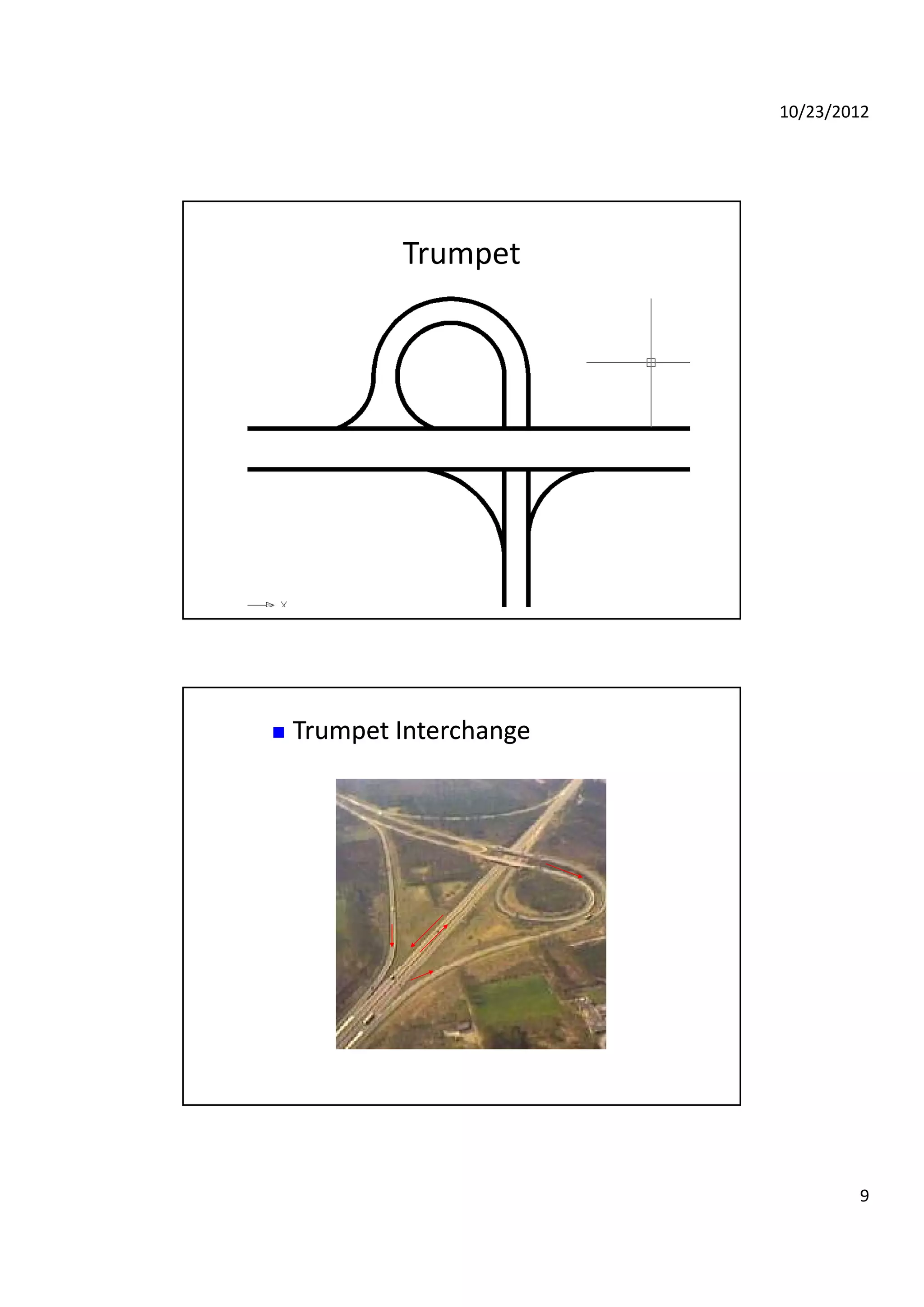
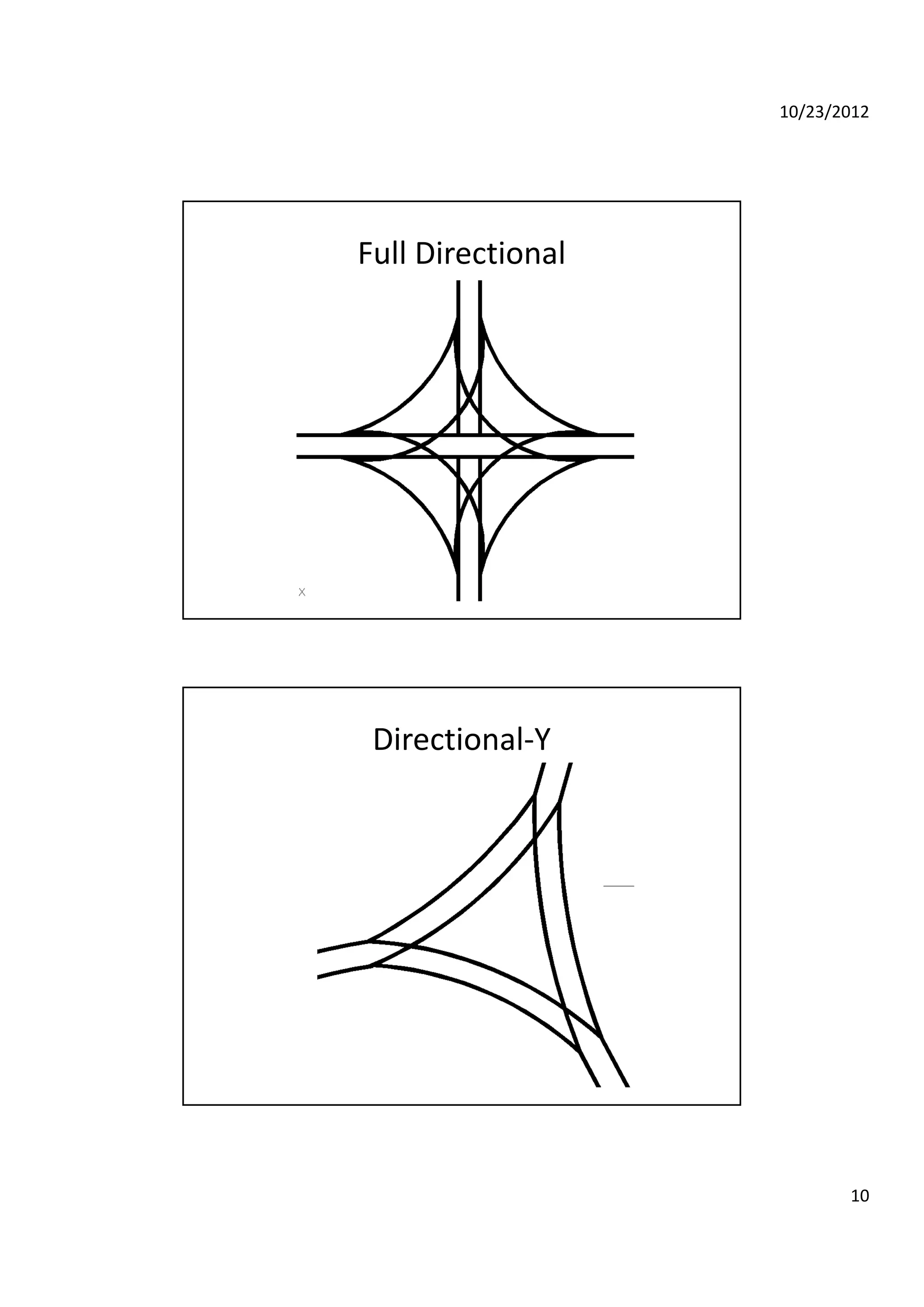
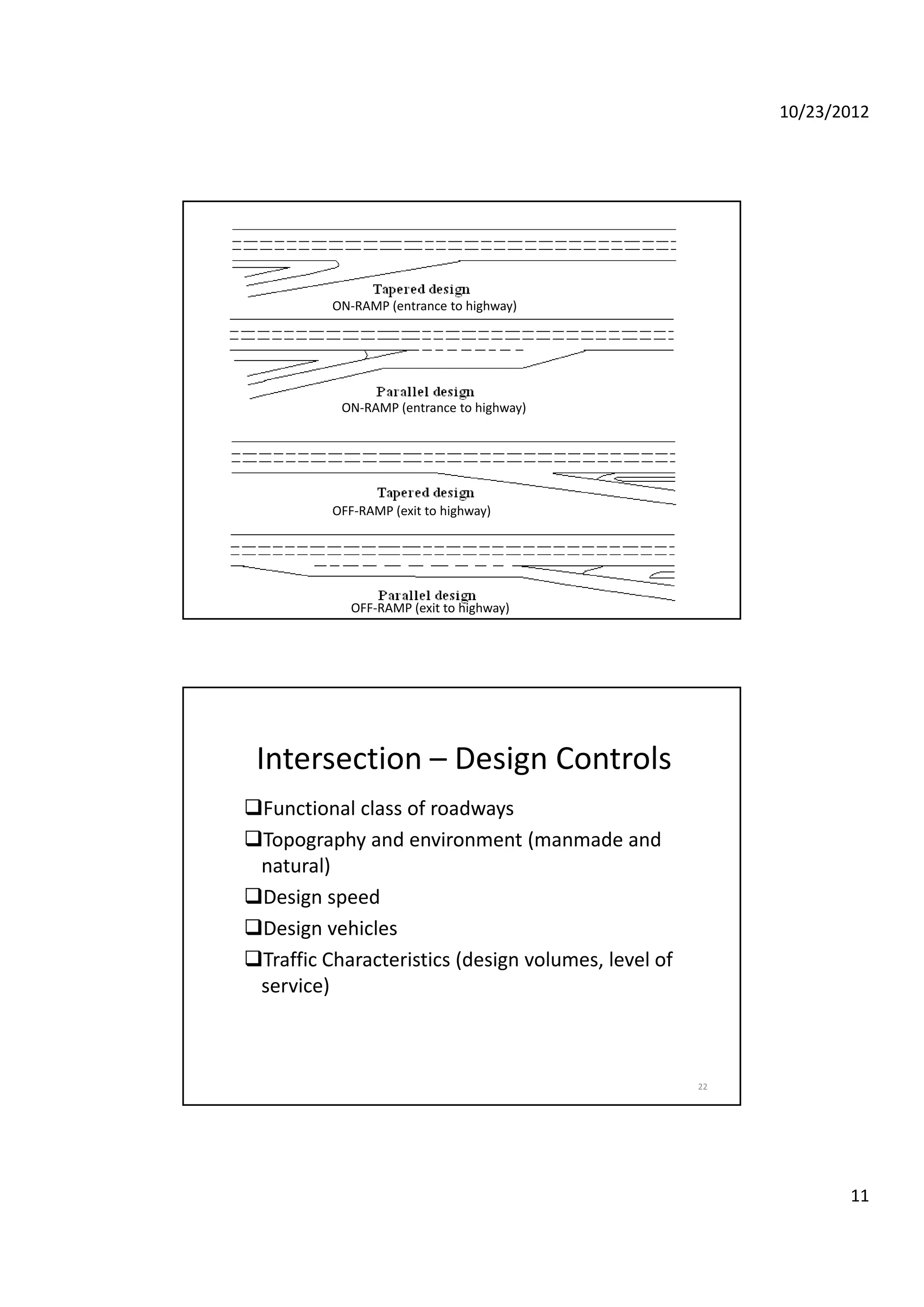
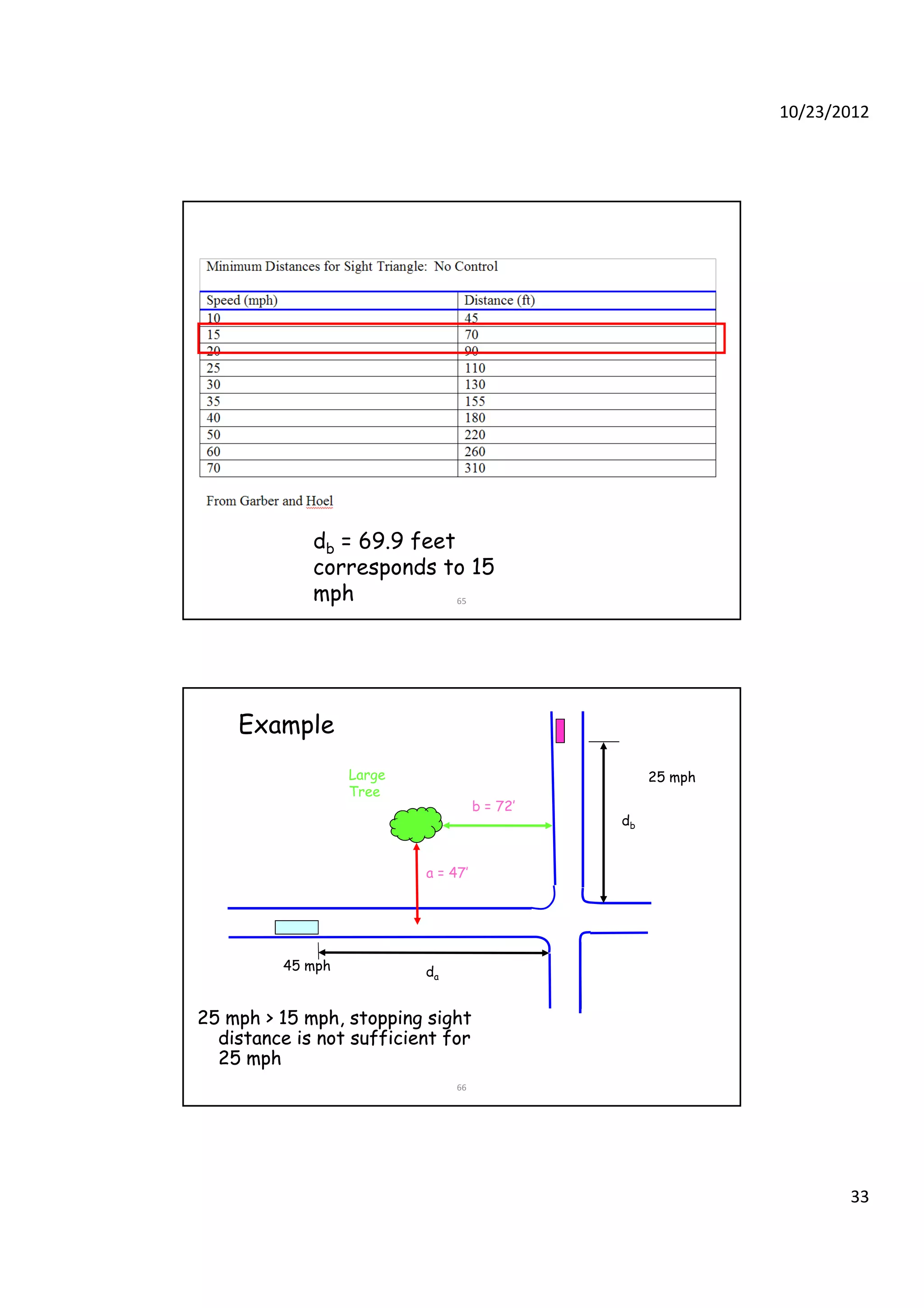
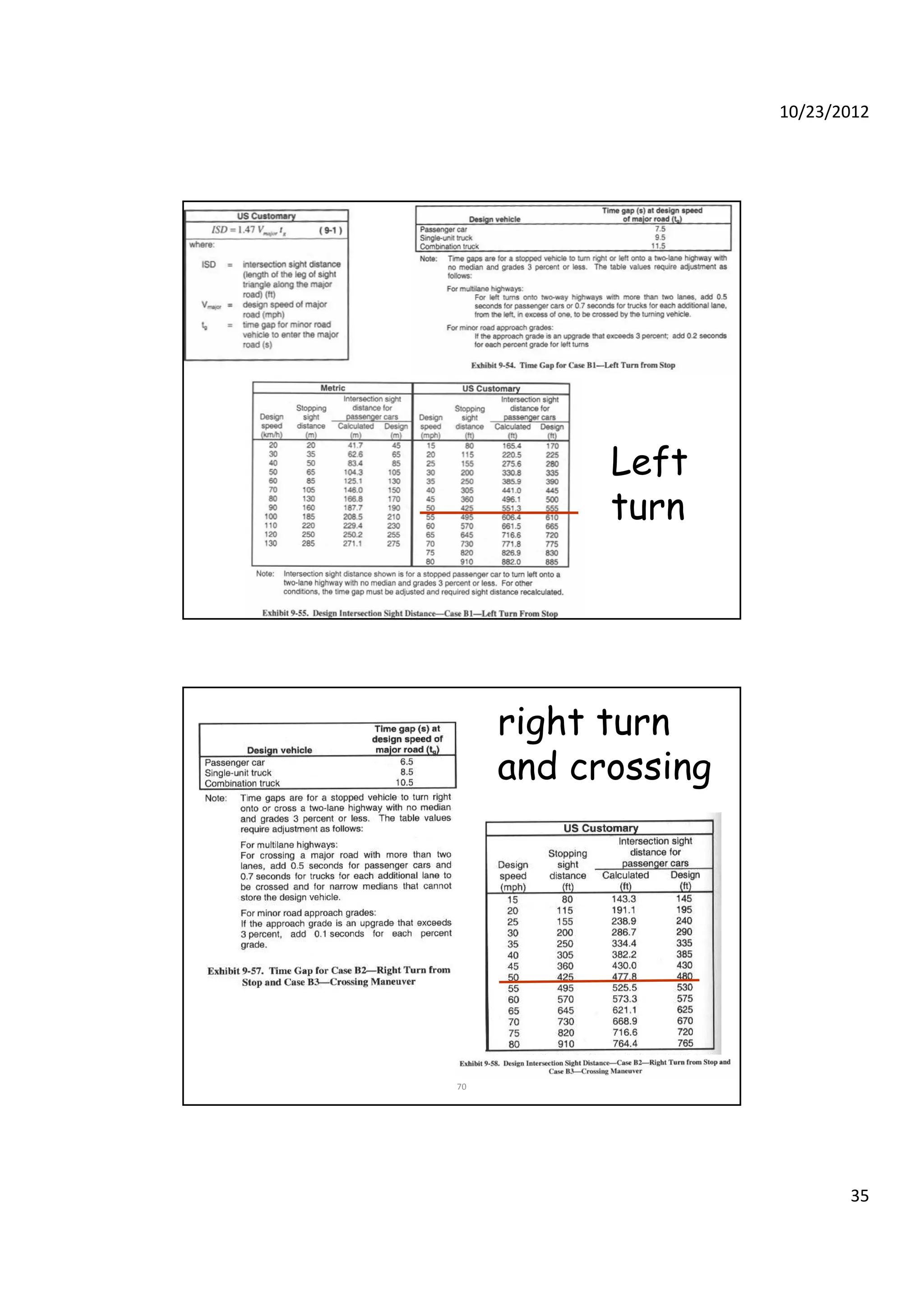

This document discusses different types of intersections and interchanges, including their key elements and design considerations. It describes at-grade intersections, channelization techniques, and different interchange configurations like diamonds, cloverleafs, and trumpets. The document also covers factors in curb radius, turn lane, and sight distance design, and provides examples of determining sufficient sight distance at intersections.


![11 Geometric Design of Railway Track [Vertical Alignment] (Railway Engineerin...](https://cdn.slidesharecdn.com/ss_thumbnails/geometricdesignofrailwaytrack-ii-200415172410-thumbnail.jpg?width=640&height=640&fit=bounds)
![10 Geometric Design of Railway Track [Horizontal Alignment] (Railway Engineer...](https://cdn.slidesharecdn.com/ss_thumbnails/geometricdesignofrailwaytrack-i-200415171932-thumbnail.jpg?width=640&height=640&fit=bounds)


