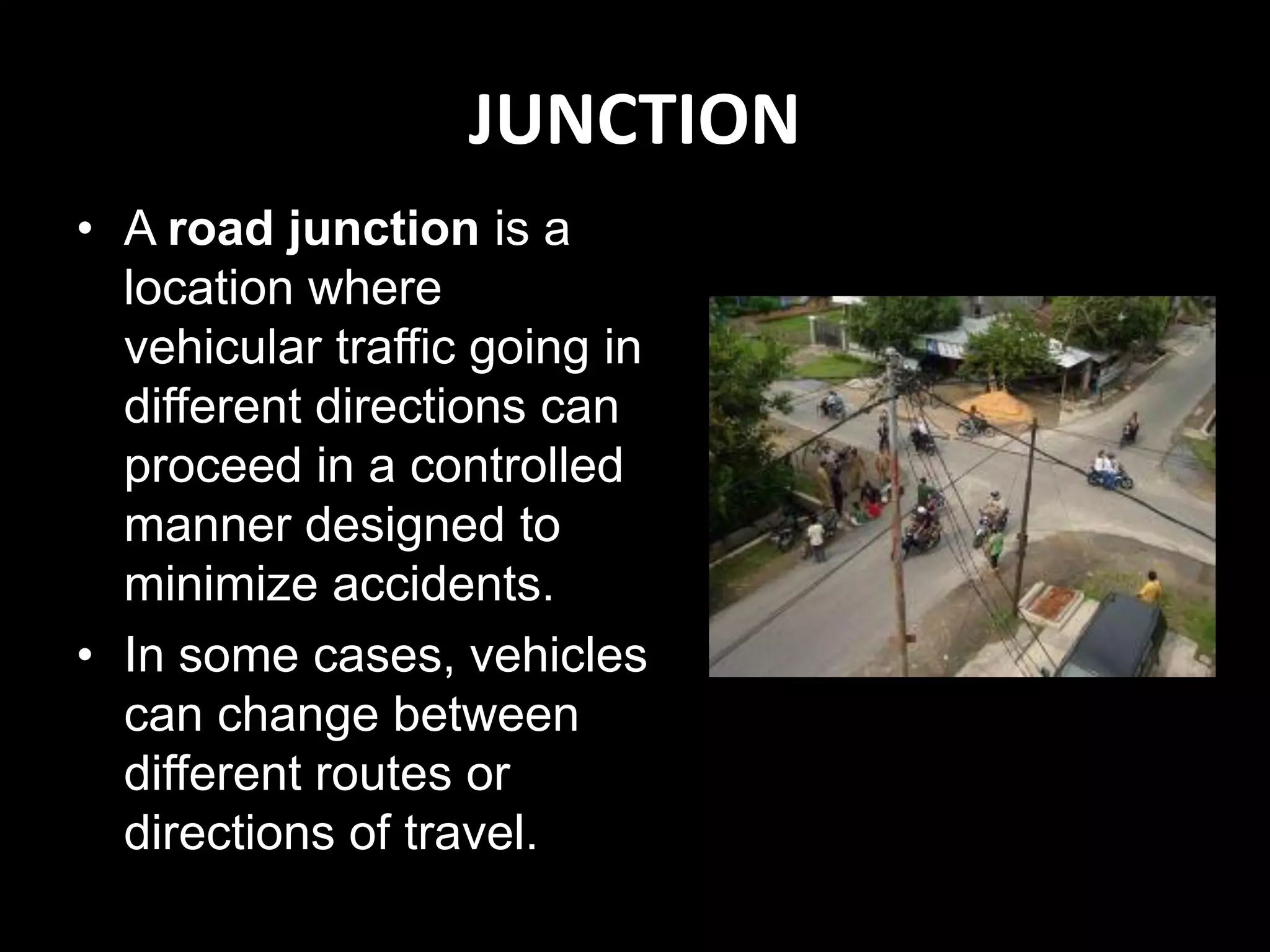
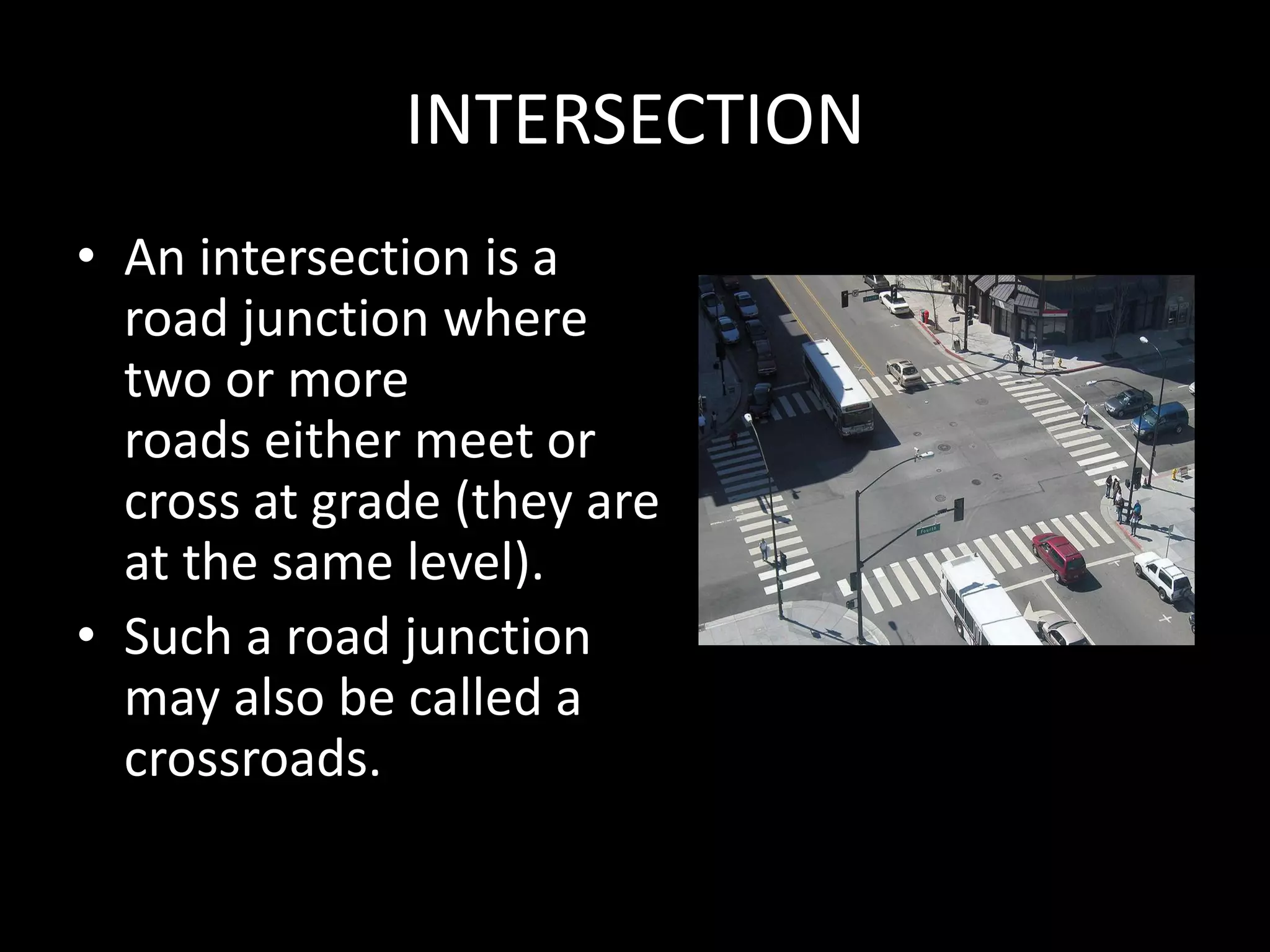
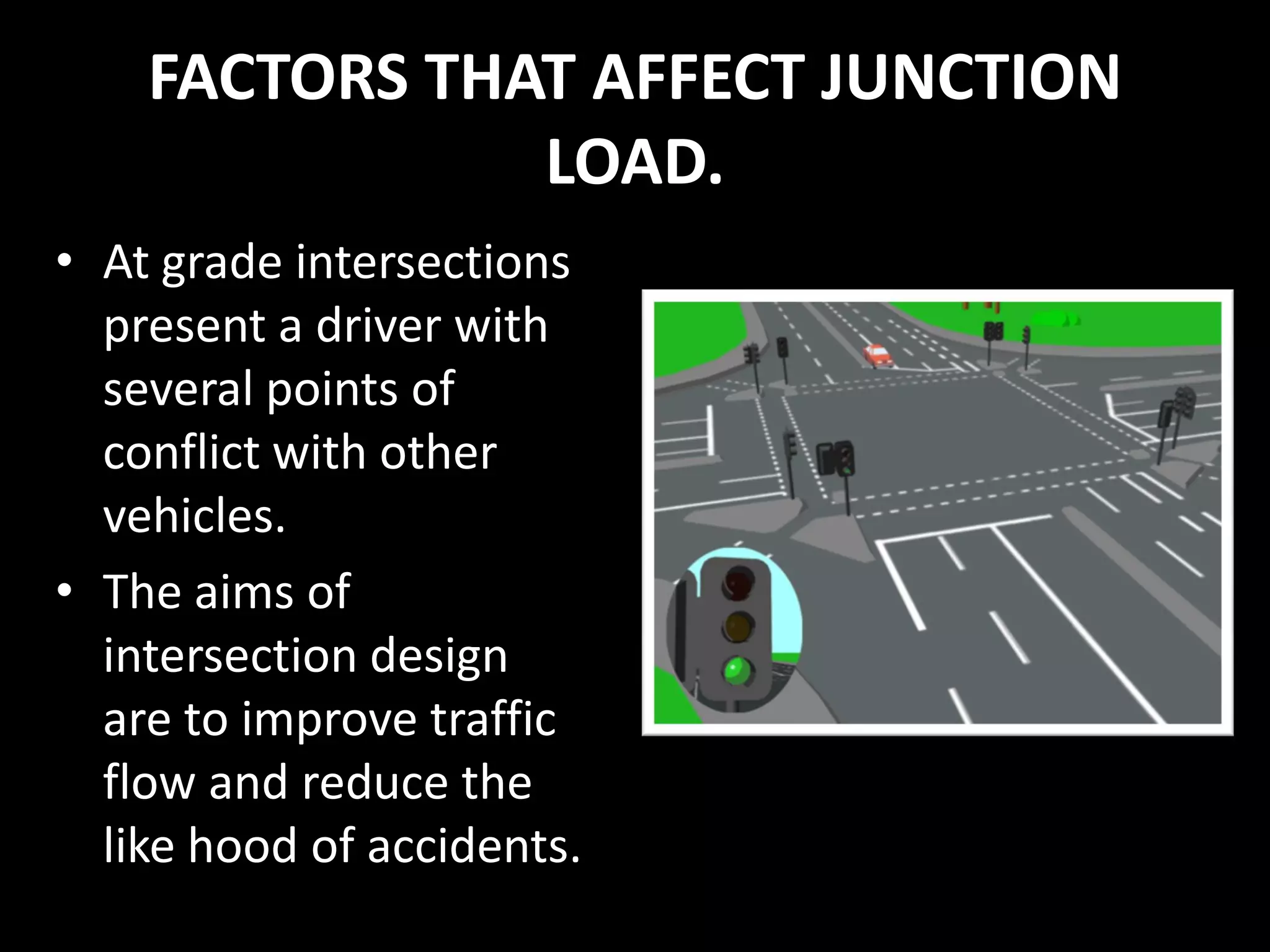
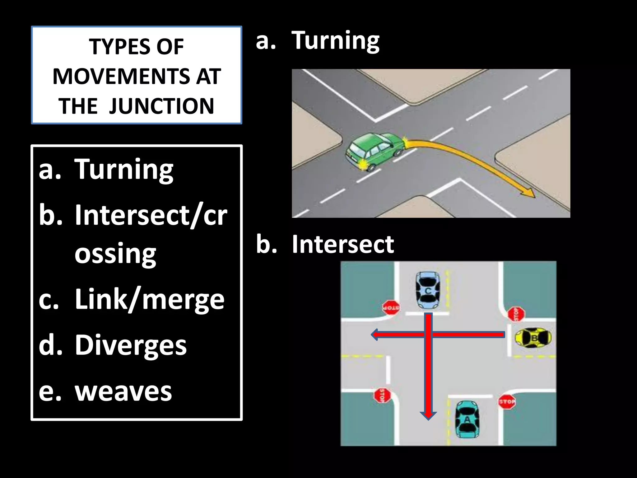
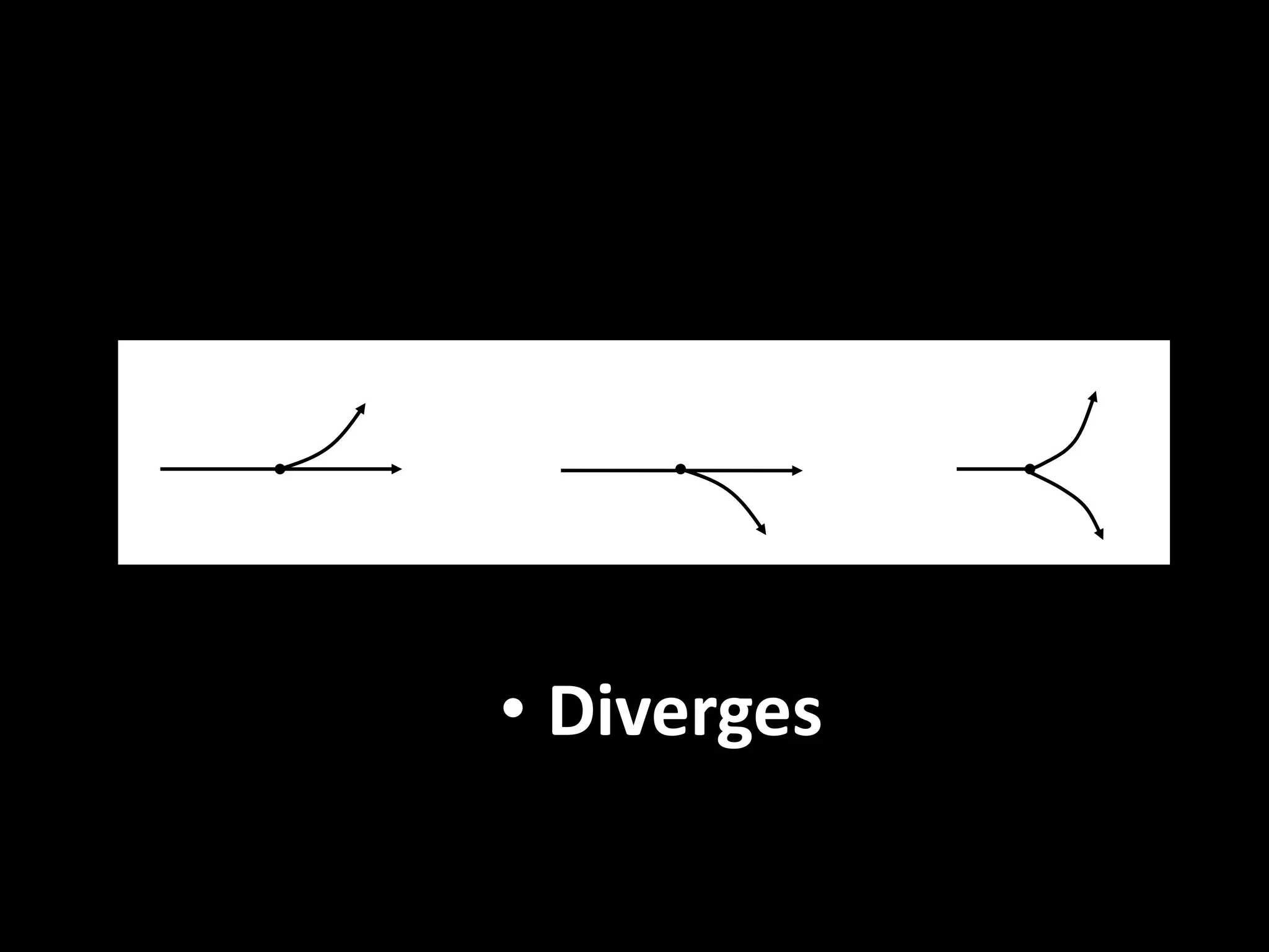
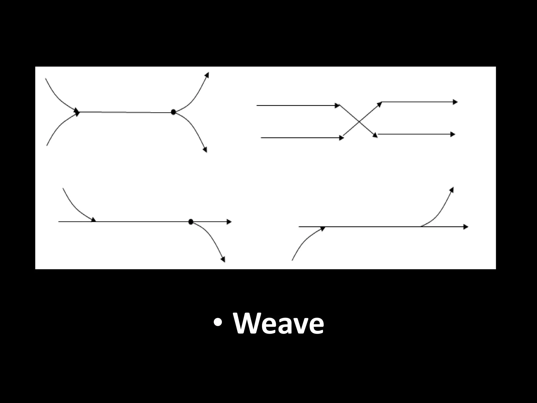
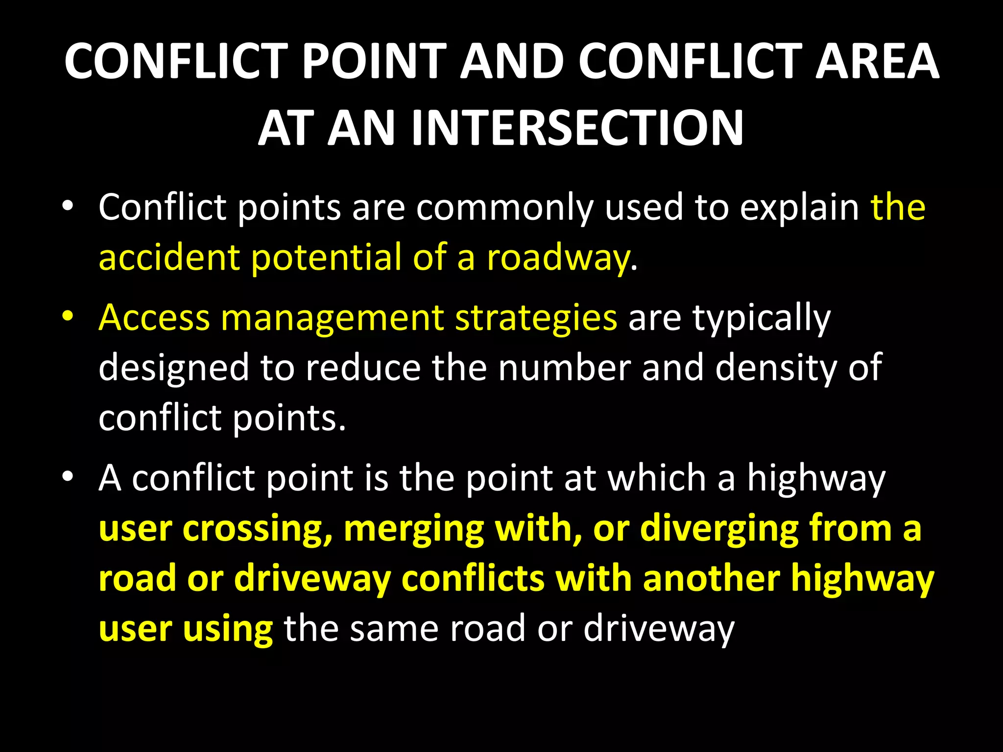
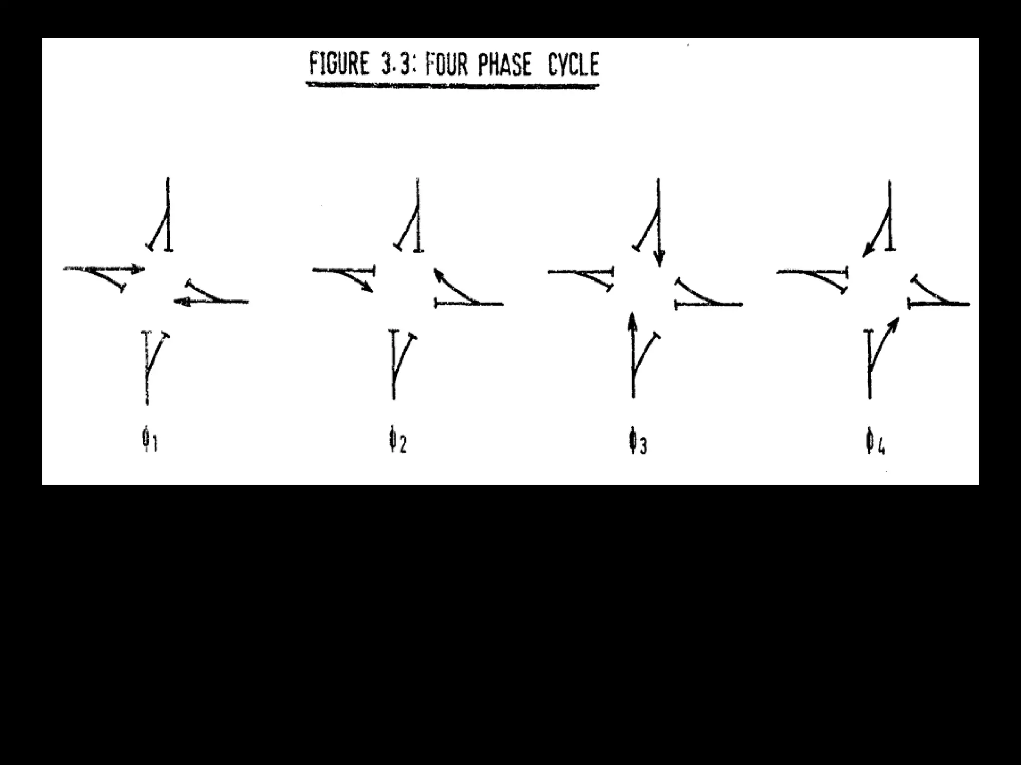
This document discusses junction design and traffic engineering. It defines different types of junctions including intersections and interchanges. Factors that affect junction loads are discussed. The types of movements at junctions like turning, merging, and diverging are also outlined. Conflict points and areas at intersections are explained. Methods to reduce conflicts at four-leg junctions using techniques like channelization are presented. Selection factors for junction types and different types of sight distances at junctions are also summarized. Finally, traffic light design and terminology used in traffic light phasing are covered.

![SIGNALIZED INTERSECTION
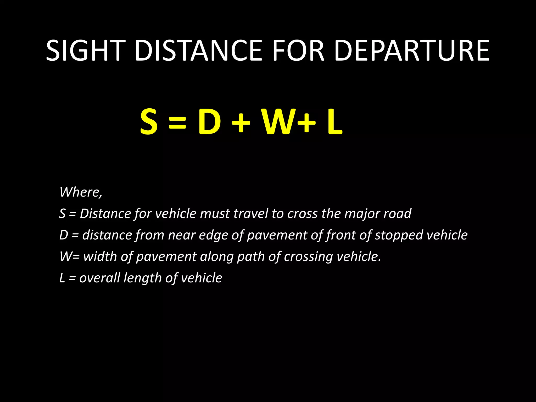
• The sight distance is the sum of a distance travelled
during the total reaction time which is the interval
between the instant that the driver recognizes the
traffic signals of the intersection ahead and the instant
that the driver actually applies the brakes, and a
distance to stop the vehicle at the stop line with
applying brake.
S = (Vt/3.6) + [ (1/2)*(V/3.6)2 ]
Where, t = 10 sec. (rural), t = 6 sec (urban),
= 0.2 x g = 0.2 x 9.8 = 1.96 m/sec2](https://image.slidesharecdn.com/chapter3-junctiondesign-140501004135-phpapp02/75/Chapter-3-junction-design-37-2048.jpg)
![STOP CONTROLLED INTERSECTION
• In this case, time for decision making as in
signalized intersection is not necessary
because every driver must stop.
S = (Vt/3.6) + [ (1/2)*(V/3.6)2 ]
Where, V= speed (km/h), t = 2 sec,
= 1.96 m/sec2](https://image.slidesharecdn.com/chapter3-junctiondesign-140501004135-phpapp02/75/Chapter-3-junction-design-38-2048.jpg)
![Example
• A vehicle travel before hit to collision point has 2
sec of reaction time to stop, deceleration of
vehicle is 1.96 m/s2 and the speed of vehicle is
100 km/hr. Determine the sight distance for a
vehicle before it hit the collision point.
Solution
S = (Vt/3.6) + [ (1/2)*(V/3.6)2 ]
= (100 x 2)/3.6 + [(1/2 x 1.96) x (100/3.6)2]
= 252.4 m](https://image.slidesharecdn.com/chapter3-junctiondesign-140501004135-phpapp02/75/Chapter-3-junction-design-41-2048.jpg)
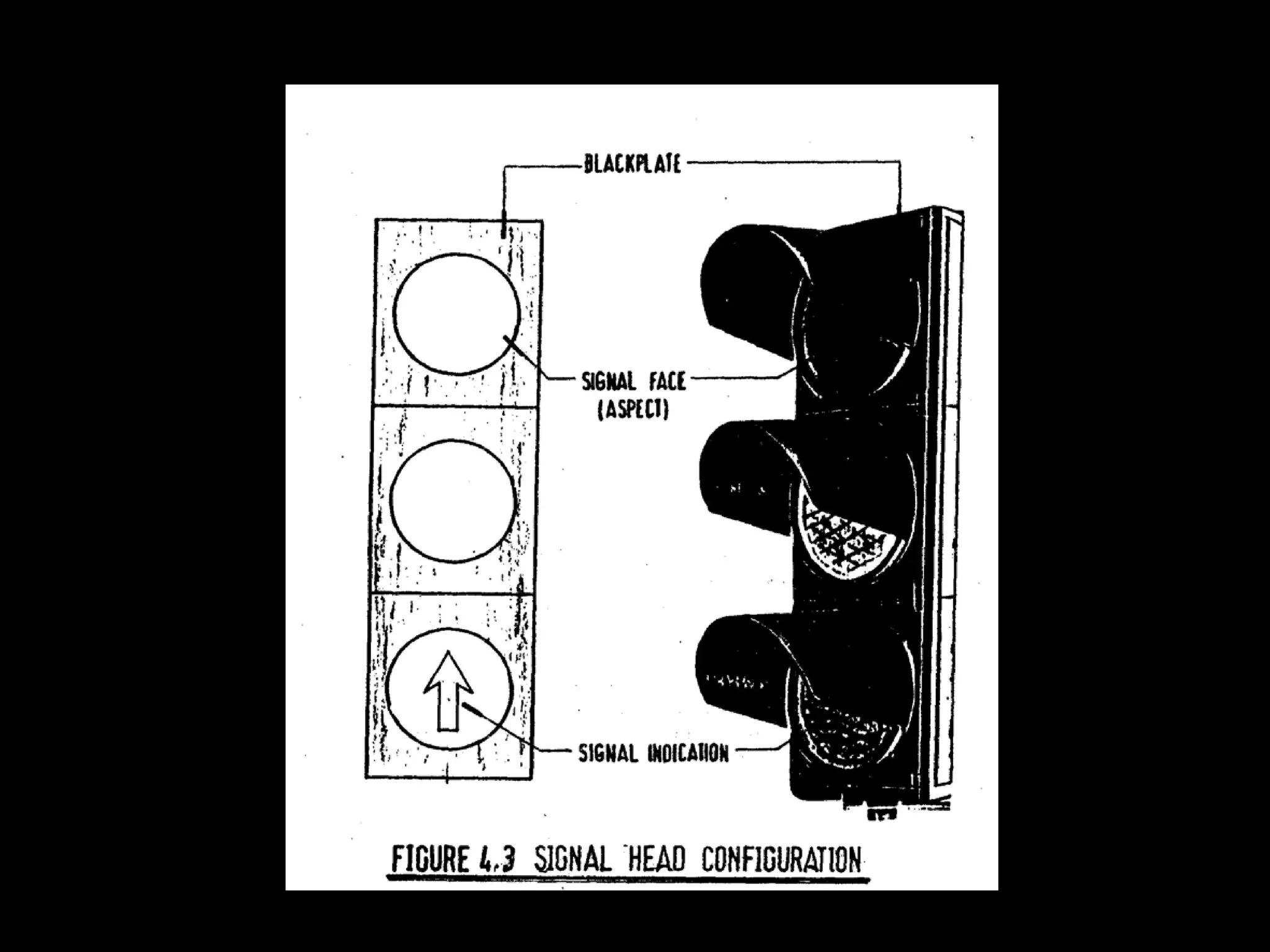
![TRAFFIC LIGHT TERM
7. CYCLE LENGTH, C
One complete sequence ( for all approaches of
signal indications [green, yellow, red] ).
Cycle time maximum (Cm) is 120 second (2
minutes) is considered as good practice.
Normally, the cycle time will lie within the range
of 30 – 90 s.](https://image.slidesharecdn.com/chapter3-junctiondesign-140501004135-phpapp02/75/Chapter-3-junction-design-53-2048.jpg)


