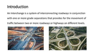
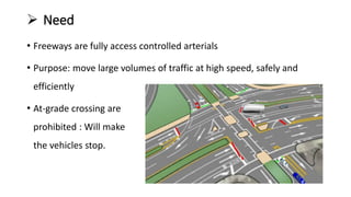
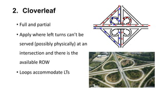
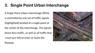
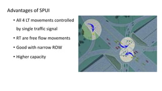
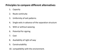
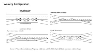
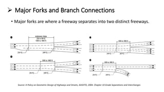
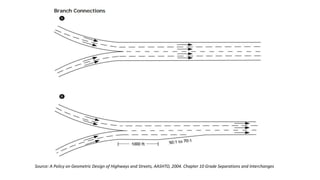
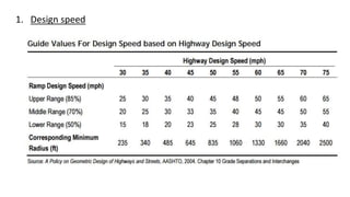
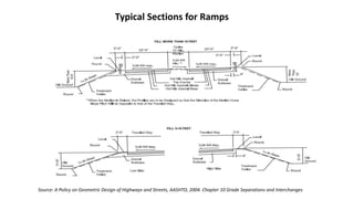
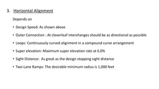
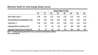
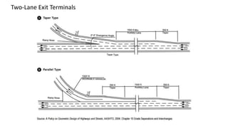
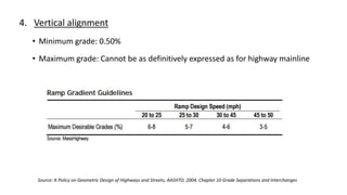
Interchange design
Raghupathi
Outline
1. Introduction & Need
2. Types of Interchanges
3. Components of interchange
4. Interchange design considerations
5. Design specifications
6. Lane balancing & weaving area
7. Ramp design
Introduction
An Interchange is a system of interconnecting roadways in conjunction
with one or more grade separations that provides for the movement of
traffic between two or more roadways or highways on different levels.
 Need
• Freeways are fully access controlled arterials
• Purpose: move large volumes of traffic at high speed, safely and
efficiently
• At-grade crossing are
prohibited : Will make
the vehicles stop.
 Interchange Warrants
1. Design Designation
2. Congestion
3. Safety
4. Topography
5. Traffic Volume
6. Road-User Benefits
Greatest efficiency,
safety and capacity
are attained
 Types of interchanges
1. Diamond
2. Cloverleaf
3. Directional
1. Diamond
• Use where intersection can handle left turns
• Simplest
• One-way diagonal ramp in each quadrant
for all turning movements
• Ramp originates/terminates at either
at-grade intersection with cross street
or junction with frontage road
Source: A Policy on Geometric
Design of Highways and Streets,
AASHTO, 2004. Chapter 10 Grade
Separations and Interchanges
Overpass or underpass?
• Depends on topography, economy, and other
minor factors
• Underpass better for deceleration/acceleration,
cost, and advance warning
• Overpass better for aesthetics
2. Cloverleaf
• Full and partial
• Apply where left turns can’t be
served (possibly physically) at an
intersection and there is the
available ROW
• Loops accommodate LTs
Advantages of Diamond Over
cloverleaf
• Requires less RW
• Left-turns travel less distance
• High speed exit/entrance
• Has expected exit/enter pattern
(versus cloverleaf with
unexpected pattern and weave
section)
• No weaving section
Advantages of Cloverleaf
over Diamond
•Left turns merge at acute angles
•Higher left turn capacity
•Turning vehicles may not have to
stop
•Don’t need median/signs to
prevent wrong way entrance
3. Single Point Urban Interchange
A Single Point Urban Interchange (SPUI)
is controlled by one set of traffic signals
(highlighted) located at a single point at
the center of the interchange. The signals
direct thru-traffic, as well as all traffic that
must turn left to enter or leave the
freeway
Advantages of SPUI
• All 4 LT movements controlled
by single traffic signal
• RT are free flow movements
• Good with narrow ROW
• Higher capacity
Disadvantages of SPUI
• High construction costs
• Difficult for pedestrians and bicyclists to negotiate
• Complex intersection and signal phases may be unfamiliar to drivers
• Streets can lead to very large areas of uncontrolled pavement
• Vehicle clearance time is longer
• Require larger bridge girder
• More free-flow motor vehicle movements
4. Directional/Semi-Directional
• Apply: freeway to freeway or other intersecting roadways with major
turning movements (where diamond, cloverleaf or SPUI can’t handle
the volumes)
• Allows higher LOS
• Advantages over cloverleaf
• Higher speed left turn
• less weaving (often none)
• normal exit/entrance patterns
Characteristics/Comparison of Basic Interchange Types
Different Configuration of interchanges
Source: A Policy on Geometric Design of Highways and Streets, AASHTO, 2004. Chapter 10 Grade Separations and Interchanges
Ramp Types
• Diagonal
• One-quadrant ramp
• Semi directional
• Outer connection
• Directional
• Loops
Source: A Policy on Geometric Design of Highways and Streets,
AASHTO, 2004. Chapter 10 Grade Separations and Interchanges
 Interchange components
https://www.fhwa.dot.gov/publications
Factors effecting to select the type of interchange are
1. Highway classification
2. Character and composition of traffic
3. Design speed
4. Degree of access control
 Interchange Design Considerations
1. Determination of Interchange Configuration
• Interchange configurations are covered in two categories,
 System interchanges: interchanges that connect two or more freeways
 Service interchanges: interchanges that connect a freeway to lesser facilities
• Different alternates are prepared based on the land use and are
compared to figure out the best
 Standard: System (freeway to freeway – directional)
Service (freeway to arterial or collector – diamond, cloverleaf, etc.)
Principles to compare different alternatives
1. Capacity
2. Route continuity
3. Uniformity of exit patterns
4. Single exits in advance of the separation structure
5. With or without weaving
6. Potential for signing
7. Cost
8. Availability of right-of-way
9. Constructability
10. compatibility with the environment.
2. Alignment, Profile and Cross Section
• The design speed, alignment, profile and cross section in the interchange area
should be consistent with those on the approaching highways.
• Four-lane roadways should be divided at interchanges
• At-grade left turns preferably should be accommodated within a suitably wide
median
3. Sight Distance
• Sight distance on the roadways through an interchange should be at a minimum
the required stopping sight distance preferably “Decision Sight Distance”
4. Interchange Spacing
• Minimum spacing is determined by
• Weaving requirements
• Ability to sign
• Lengths of speed change lanes
• Capacity of the main facility
• Interchanges an average minimum spacing of
• Urban areas: 2 miles
• Suburban sections 4 miles
• Rural areas 8 miles.
• In urban areas, the minimum distance between adjacent interchanges
should not be less than 1 mile, and in rural areas not less than 3 miles
5. Uniformity of Interchange Patterns
• Interchanges along a freeway should be reasonably uniform in geometric layout
and general appearance.
• Provides the appropriate LOS and maximum safety in conjunction.
• Highly special cases, all entrance and exit ramps should be on the right.
6. Route Continuity
• Simplifies the driving task
 Reduces lane changes
 Simplifies signing
 Delineates the through route
7. Signing and Marking
• Safety, efficiency and clarity of paths largely depends on Signing and Marking
• Signing and marking should conform to the OMUTCD (Ohio Manual of Uniform Traffic
Control Devices)
8. Basic Number of Lanes
• The minimum number of lanes needed over a significant length of a highway
based on the overall capacity needs of that section.
• The number of lanes should remain constant over short distances
Interchanges on Freeways as Related to Types of Intersecting Facilities
and Surrounding Area are shown
Source: A Policy on Geometric Design of Highways and Streets, AASHTO, 2004. Chapter 10 Grade Separations and Interchanges
 Design specifications
1. Cross slope and shoulder
• Minimum 2 through lanes 1.5 to 2% cross-slope
• Continuous paved shoulder
 Right: 10 ft
 Left: 4 to 8 ft
2. Clearance
• Vertical clearance: at least 16 ft over entire cross-section
(Consider future resurfacing)
• Horizontal: clear zone consistent with operating speed and side slopes
Medians:
Rural: 50 to 100 ft
Urban
For 4 lane use 10 ft (2x4 ft shoulder + barrier)
For 6 lane use 22 ft (2x10 ft shoulder + barrier)
3. Minimum Grades for urban and rural freeways
Source: A Policy on Geometric Design of Highways and Streets, AASHTO, 2004. Chapter 10 Grade Separations and Interchanges
Minimum distance required to attain effect grade separation
Source: A Policy on Geometric Design of Highways and Streets, AASHTO, 2004. Chapter 10 Grade Separations and Interchanges
4. Design speed:
5. Design Widths for Turning Roadways
Source: A Policy on Geometric Design of Highways and Streets, AASHTO, 2004. Chapter 10 Grade Separations and Interchanges
 Lane balance
• Number of mainline lanes leaving the diverging
nose must be equal to the number of mainline
lanes approaching the nose.
• The total number of lanes leaving the diverging
nose (mainline lanes plus diverging lanes)
must be one greater than the total number
of lanes approaching the nose to obtain
lane balance
http://onlinepubs.trb.org
Source: A Policy on Geometric Design of Highways and Streets,
AASHTO, 2004. Chapter 10 Grade Separations and Interchanges
Typical example of lane balance Coordination of lane balance and basic number of lanes
Multilane exit ramps and diverging
roadways
Source: A Policy on Geometric Design of Highways and Streets, AASHTO, 2004. Chapter 10 Grade Separations and Interchanges
High speed two-lane exit terminals
Source: A Policy on Geometric Design of Highways and Streets, AASHTO, 2004. Chapter 10 Grade Separations and Interchanges
 Weaving Areas
• Weaving occurs where one-way traffic streams cross by merging and
diverging maneuvers
Source: A Policy on Geometric Design of Highways and Streets, AASHTO, 2004. Chapter 10 Grade Separations and Interchanges
Weaving Configuration
Source: A Policy on Geometric Design of Highways and Streets, AASHTO, 2004. Chapter 10 Grade Separations and Interchanges
 Major Forks and Branch Connections
• Major forks are where a freeway separates into two distinct freeways.
Source: A Policy on Geometric Design of Highways and Streets, AASHTO, 2004. Chapter 10 Grade Separations and Interchanges
 Ramp Design
Ramp: All types, arrangements, and sizes of turning roadways that
connect two or more legs at an interchange
1. Geometric design
It includes
1. Design speed
2. Cross section
3. Horizontal alignment
4. Vertical alignment
1. Design speed
2. Cross Section
• Ramp Width –22 feet for one-lane ramps and 30 feet for two-lane ramps.
• Cross Slope – Tangent sections-uniformly sloped at 2.0% from the median edge to
the opposite edge. maximum super elevation rate at 6.0%.
• Side Slopes – should be 1:6 or flatter.
• Lateral Clearances to Obstructions (Clear Zones)
o Clear zone widths vary from 6-10 feet at 40 mph to 40-50 feet at 70 mph.
o lateral clearance on the right outside of the edge of traveled way of at least 6 feet and
preferably 8 to 10 feet,
o lateral clearance on the left of at least 4 feet beyond the edge of the traveled way
• Exit Ramp Entrance Width
o Where the through lane and exit ramp diverge, width will be 25 feet
o This width will be maintained until the gore nose is reached and transitioned to the standard 22
feet width at approximately a 12:1 rate.
• Entrance Ramp Terminal Width
o The standard 22 feet width will be transitioned to 14 feet width at the convergence with the
through lane
Typical Sections for Ramps
Source: A Policy on Geometric Design of Highways and Streets, AASHTO, 2004. Chapter 10 Grade Separations and Interchanges
3. Horizontal Alignment
Depends on
• Design Speed: As shown above
• Outer Connection : At cloverleaf interchanges should be as directional as possible
• Loops: Continuously curved alignment in a compound curve arrangement
• Super elevation: Maximum super elevation rate at 6.0%
• Sight Distance: As great as the design stopping sight distance
• Two-Lane Ramps: The desirable minimum radius is 1,000 feet
Source: A Policy on Geometric Design of Highways and Streets, AASHTO, 2004. Chapter 10 Grade Separations and Interchanges
Two-Lane Exit Terminals
4. Vertical alignment
• Minimum grade: 0.50%
• Maximum grade: Cannot be as definitively expressed as for highway mainline
Source: A Policy on Geometric Design of Highways and Streets, AASHTO, 2004. Chapter 10 Grade Separations and Interchanges
2. Capacity
• Although up to 1,700 pcph can be accommodated on a single-lane ramp,
freeway/ramp junctions are not capable of handling this volume
• 1,500 pcph should be used as a threshold.

Interchange design

  • 1.
  • 2.
    Outline 1. Introduction &Need 2. Types of Interchanges 3. Components of interchange 4. Interchange design considerations 5. Design specifications 6. Lane balancing & weaving area 7. Ramp design
  • 3.
    Introduction An Interchange isa system of interconnecting roadways in conjunction with one or more grade separations that provides for the movement of traffic between two or more roadways or highways on different levels.
  • 4.
     Need • Freewaysare fully access controlled arterials • Purpose: move large volumes of traffic at high speed, safely and efficiently • At-grade crossing are prohibited : Will make the vehicles stop.
  • 5.
     Interchange Warrants 1.Design Designation 2. Congestion 3. Safety 4. Topography 5. Traffic Volume 6. Road-User Benefits Greatest efficiency, safety and capacity are attained
  • 6.
     Types ofinterchanges 1. Diamond 2. Cloverleaf 3. Directional
  • 7.
    1. Diamond • Usewhere intersection can handle left turns • Simplest • One-way diagonal ramp in each quadrant for all turning movements • Ramp originates/terminates at either at-grade intersection with cross street or junction with frontage road Source: A Policy on Geometric Design of Highways and Streets, AASHTO, 2004. Chapter 10 Grade Separations and Interchanges
  • 8.
    Overpass or underpass? •Depends on topography, economy, and other minor factors • Underpass better for deceleration/acceleration, cost, and advance warning • Overpass better for aesthetics
  • 9.
    2. Cloverleaf • Fulland partial • Apply where left turns can’t be served (possibly physically) at an intersection and there is the available ROW • Loops accommodate LTs
  • 10.
    Advantages of DiamondOver cloverleaf • Requires less RW • Left-turns travel less distance • High speed exit/entrance • Has expected exit/enter pattern (versus cloverleaf with unexpected pattern and weave section) • No weaving section Advantages of Cloverleaf over Diamond •Left turns merge at acute angles •Higher left turn capacity •Turning vehicles may not have to stop •Don’t need median/signs to prevent wrong way entrance
  • 11.
    3. Single PointUrban Interchange A Single Point Urban Interchange (SPUI) is controlled by one set of traffic signals (highlighted) located at a single point at the center of the interchange. The signals direct thru-traffic, as well as all traffic that must turn left to enter or leave the freeway
  • 12.
    Advantages of SPUI •All 4 LT movements controlled by single traffic signal • RT are free flow movements • Good with narrow ROW • Higher capacity
  • 13.
    Disadvantages of SPUI •High construction costs • Difficult for pedestrians and bicyclists to negotiate • Complex intersection and signal phases may be unfamiliar to drivers • Streets can lead to very large areas of uncontrolled pavement • Vehicle clearance time is longer • Require larger bridge girder • More free-flow motor vehicle movements
  • 14.
    4. Directional/Semi-Directional • Apply:freeway to freeway or other intersecting roadways with major turning movements (where diamond, cloverleaf or SPUI can’t handle the volumes) • Allows higher LOS • Advantages over cloverleaf • Higher speed left turn • less weaving (often none) • normal exit/entrance patterns
  • 15.
  • 16.
    Different Configuration ofinterchanges Source: A Policy on Geometric Design of Highways and Streets, AASHTO, 2004. Chapter 10 Grade Separations and Interchanges
  • 17.
    Ramp Types • Diagonal •One-quadrant ramp • Semi directional • Outer connection • Directional • Loops Source: A Policy on Geometric Design of Highways and Streets, AASHTO, 2004. Chapter 10 Grade Separations and Interchanges
  • 18.
  • 19.
    Factors effecting toselect the type of interchange are 1. Highway classification 2. Character and composition of traffic 3. Design speed 4. Degree of access control
  • 20.
     Interchange DesignConsiderations 1. Determination of Interchange Configuration • Interchange configurations are covered in two categories,  System interchanges: interchanges that connect two or more freeways  Service interchanges: interchanges that connect a freeway to lesser facilities • Different alternates are prepared based on the land use and are compared to figure out the best  Standard: System (freeway to freeway – directional) Service (freeway to arterial or collector – diamond, cloverleaf, etc.)
  • 21.
    Principles to comparedifferent alternatives 1. Capacity 2. Route continuity 3. Uniformity of exit patterns 4. Single exits in advance of the separation structure 5. With or without weaving 6. Potential for signing 7. Cost 8. Availability of right-of-way 9. Constructability 10. compatibility with the environment.
  • 22.
    2. Alignment, Profileand Cross Section • The design speed, alignment, profile and cross section in the interchange area should be consistent with those on the approaching highways. • Four-lane roadways should be divided at interchanges • At-grade left turns preferably should be accommodated within a suitably wide median 3. Sight Distance • Sight distance on the roadways through an interchange should be at a minimum the required stopping sight distance preferably “Decision Sight Distance”
  • 23.
    4. Interchange Spacing •Minimum spacing is determined by • Weaving requirements • Ability to sign • Lengths of speed change lanes • Capacity of the main facility • Interchanges an average minimum spacing of • Urban areas: 2 miles • Suburban sections 4 miles • Rural areas 8 miles. • In urban areas, the minimum distance between adjacent interchanges should not be less than 1 mile, and in rural areas not less than 3 miles
  • 24.
    5. Uniformity ofInterchange Patterns • Interchanges along a freeway should be reasonably uniform in geometric layout and general appearance. • Provides the appropriate LOS and maximum safety in conjunction. • Highly special cases, all entrance and exit ramps should be on the right. 6. Route Continuity • Simplifies the driving task  Reduces lane changes  Simplifies signing  Delineates the through route
  • 25.
    7. Signing andMarking • Safety, efficiency and clarity of paths largely depends on Signing and Marking • Signing and marking should conform to the OMUTCD (Ohio Manual of Uniform Traffic Control Devices) 8. Basic Number of Lanes • The minimum number of lanes needed over a significant length of a highway based on the overall capacity needs of that section. • The number of lanes should remain constant over short distances
  • 26.
    Interchanges on Freewaysas Related to Types of Intersecting Facilities and Surrounding Area are shown Source: A Policy on Geometric Design of Highways and Streets, AASHTO, 2004. Chapter 10 Grade Separations and Interchanges
  • 27.
     Design specifications 1.Cross slope and shoulder • Minimum 2 through lanes 1.5 to 2% cross-slope • Continuous paved shoulder  Right: 10 ft  Left: 4 to 8 ft 2. Clearance • Vertical clearance: at least 16 ft over entire cross-section (Consider future resurfacing) • Horizontal: clear zone consistent with operating speed and side slopes
  • 28.
    Medians: Rural: 50 to100 ft Urban For 4 lane use 10 ft (2x4 ft shoulder + barrier) For 6 lane use 22 ft (2x10 ft shoulder + barrier) 3. Minimum Grades for urban and rural freeways Source: A Policy on Geometric Design of Highways and Streets, AASHTO, 2004. Chapter 10 Grade Separations and Interchanges
  • 29.
    Minimum distance requiredto attain effect grade separation Source: A Policy on Geometric Design of Highways and Streets, AASHTO, 2004. Chapter 10 Grade Separations and Interchanges
  • 30.
  • 31.
    5. Design Widthsfor Turning Roadways Source: A Policy on Geometric Design of Highways and Streets, AASHTO, 2004. Chapter 10 Grade Separations and Interchanges
  • 32.
     Lane balance •Number of mainline lanes leaving the diverging nose must be equal to the number of mainline lanes approaching the nose. • The total number of lanes leaving the diverging nose (mainline lanes plus diverging lanes) must be one greater than the total number of lanes approaching the nose to obtain lane balance http://onlinepubs.trb.org
  • 33.
    Source: A Policyon Geometric Design of Highways and Streets, AASHTO, 2004. Chapter 10 Grade Separations and Interchanges Typical example of lane balance Coordination of lane balance and basic number of lanes
  • 34.
    Multilane exit rampsand diverging roadways Source: A Policy on Geometric Design of Highways and Streets, AASHTO, 2004. Chapter 10 Grade Separations and Interchanges
  • 35.
    High speed two-laneexit terminals Source: A Policy on Geometric Design of Highways and Streets, AASHTO, 2004. Chapter 10 Grade Separations and Interchanges
  • 36.
     Weaving Areas •Weaving occurs where one-way traffic streams cross by merging and diverging maneuvers Source: A Policy on Geometric Design of Highways and Streets, AASHTO, 2004. Chapter 10 Grade Separations and Interchanges
  • 37.
    Weaving Configuration Source: APolicy on Geometric Design of Highways and Streets, AASHTO, 2004. Chapter 10 Grade Separations and Interchanges
  • 38.
     Major Forksand Branch Connections • Major forks are where a freeway separates into two distinct freeways. Source: A Policy on Geometric Design of Highways and Streets, AASHTO, 2004. Chapter 10 Grade Separations and Interchanges
  • 39.
    Source: A Policyon Geometric Design of Highways and Streets, AASHTO, 2004. Chapter 10 Grade Separations and Interchanges
  • 40.
     Ramp Design Ramp:All types, arrangements, and sizes of turning roadways that connect two or more legs at an interchange 1. Geometric design It includes 1. Design speed 2. Cross section 3. Horizontal alignment 4. Vertical alignment
  • 41.
  • 42.
    2. Cross Section •Ramp Width –22 feet for one-lane ramps and 30 feet for two-lane ramps. • Cross Slope – Tangent sections-uniformly sloped at 2.0% from the median edge to the opposite edge. maximum super elevation rate at 6.0%. • Side Slopes – should be 1:6 or flatter. • Lateral Clearances to Obstructions (Clear Zones) o Clear zone widths vary from 6-10 feet at 40 mph to 40-50 feet at 70 mph. o lateral clearance on the right outside of the edge of traveled way of at least 6 feet and preferably 8 to 10 feet, o lateral clearance on the left of at least 4 feet beyond the edge of the traveled way
  • 43.
    • Exit RampEntrance Width o Where the through lane and exit ramp diverge, width will be 25 feet o This width will be maintained until the gore nose is reached and transitioned to the standard 22 feet width at approximately a 12:1 rate. • Entrance Ramp Terminal Width o The standard 22 feet width will be transitioned to 14 feet width at the convergence with the through lane
  • 44.
    Typical Sections forRamps Source: A Policy on Geometric Design of Highways and Streets, AASHTO, 2004. Chapter 10 Grade Separations and Interchanges
  • 45.
    3. Horizontal Alignment Dependson • Design Speed: As shown above • Outer Connection : At cloverleaf interchanges should be as directional as possible • Loops: Continuously curved alignment in a compound curve arrangement • Super elevation: Maximum super elevation rate at 6.0% • Sight Distance: As great as the design stopping sight distance • Two-Lane Ramps: The desirable minimum radius is 1,000 feet
  • 46.
    Source: A Policyon Geometric Design of Highways and Streets, AASHTO, 2004. Chapter 10 Grade Separations and Interchanges
  • 47.
  • 48.
    4. Vertical alignment •Minimum grade: 0.50% • Maximum grade: Cannot be as definitively expressed as for highway mainline Source: A Policy on Geometric Design of Highways and Streets, AASHTO, 2004. Chapter 10 Grade Separations and Interchanges
  • 49.
    2. Capacity • Althoughup to 1,700 pcph can be accommodated on a single-lane ramp, freeway/ramp junctions are not capable of handling this volume • 1,500 pcph should be used as a threshold.

Editor's Notes