This document discusses key aspects of highway geometric design, including:
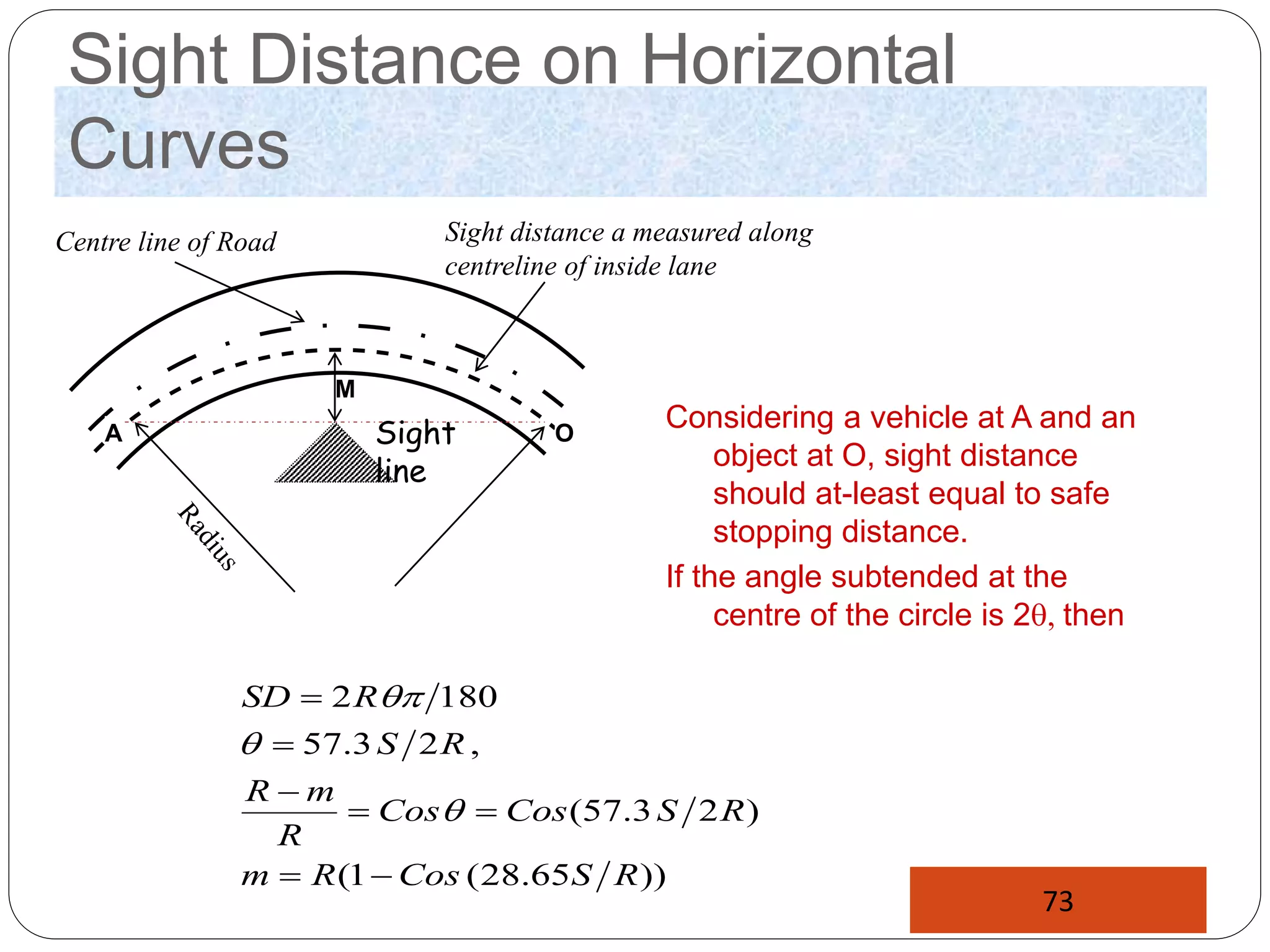
- Highway geometric design involves designing elements like cross-sections, horizontal and vertical alignments, sight distances, and intersections within economic limitations and traffic requirements.
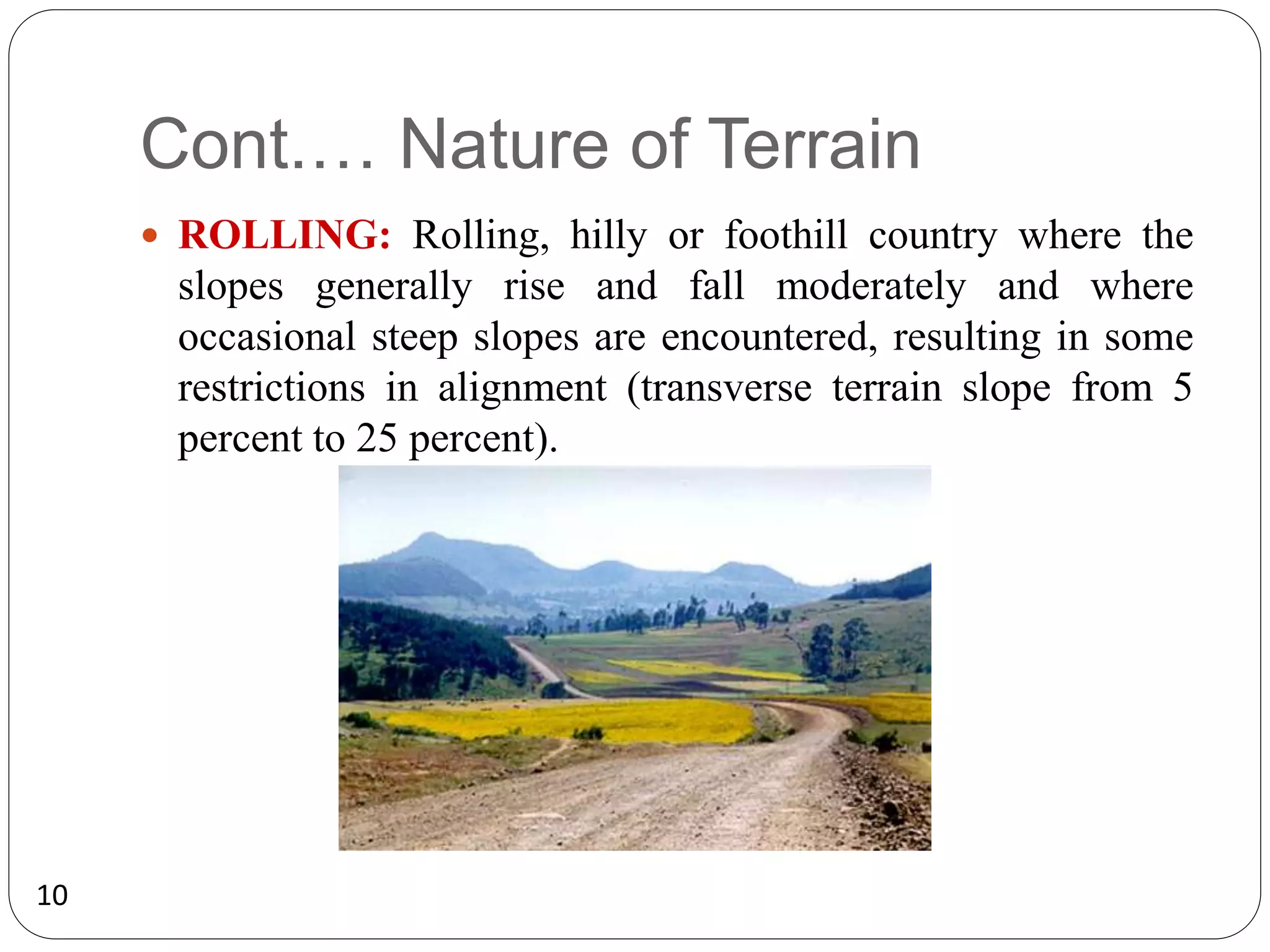
- Design controls and criteria are influenced by factors such as road classification, terrain, traffic volumes, design vehicle, design speed, sight distance, and land use.
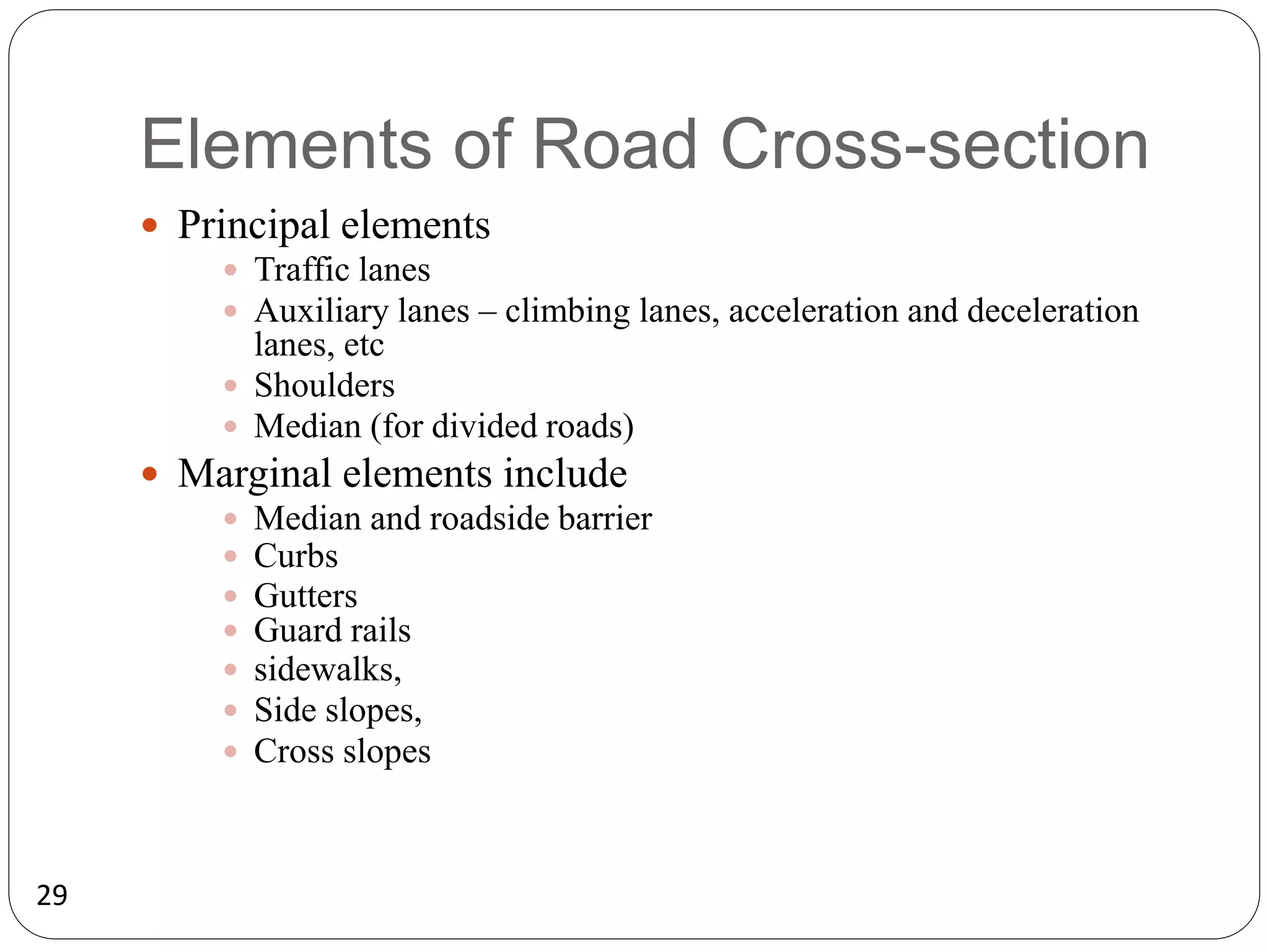
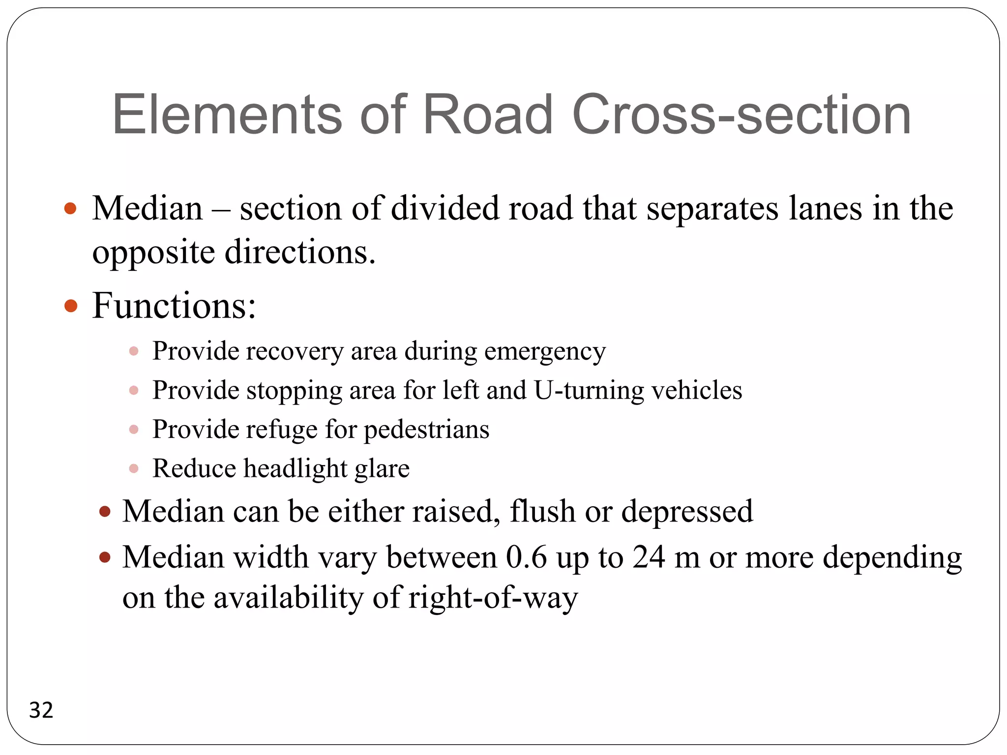
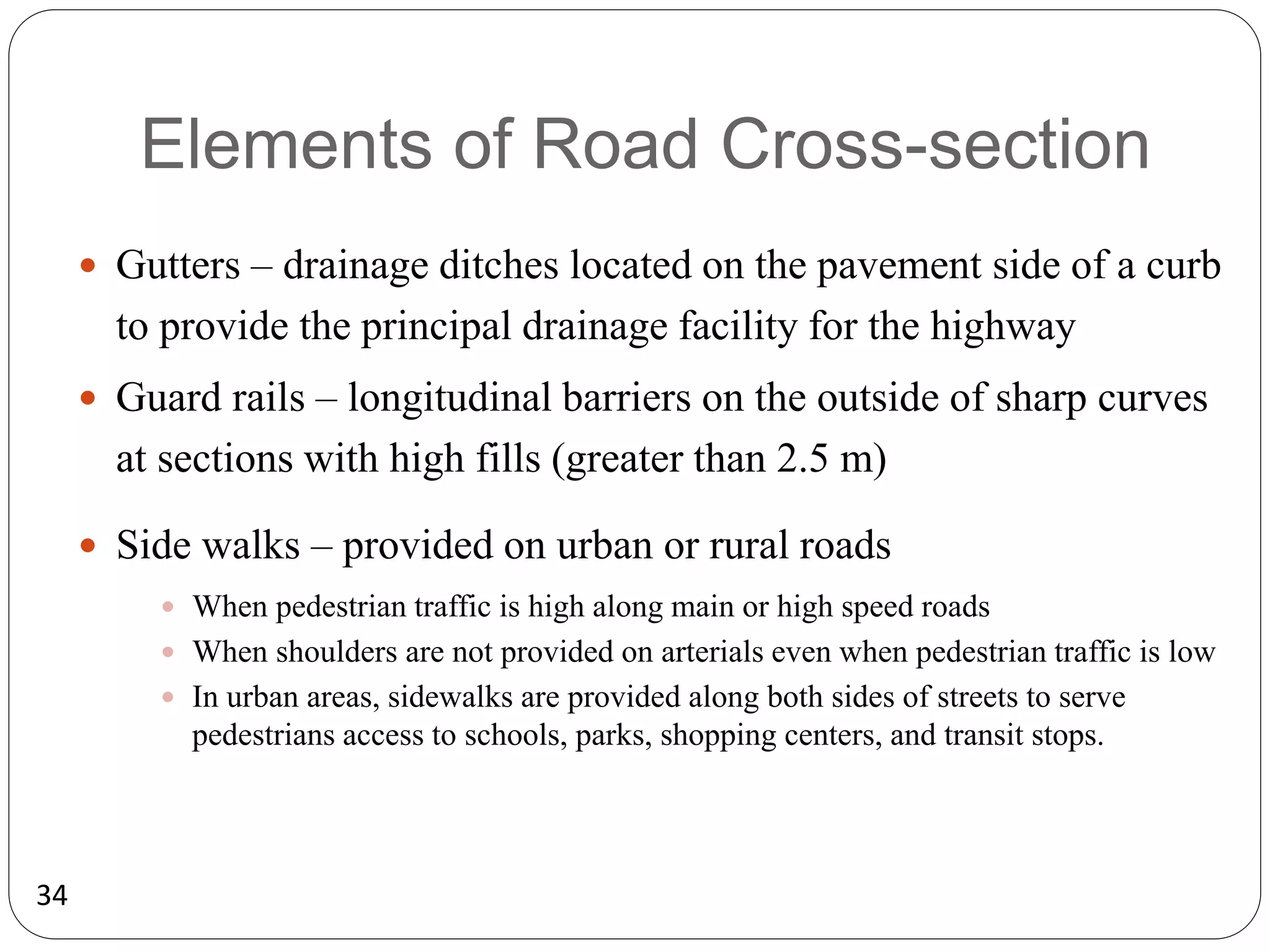
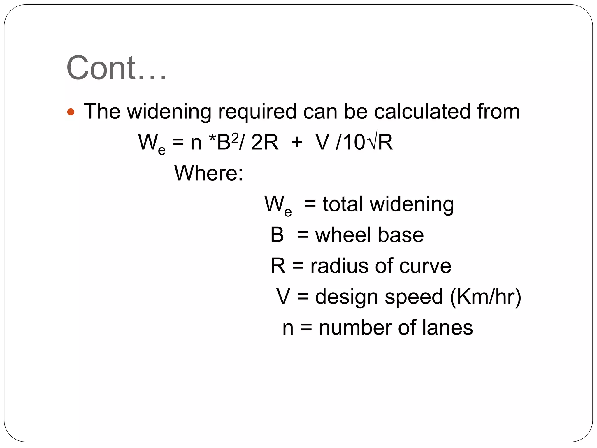
- Elements of road cross-sections include traffic lanes, shoulders, medians, barriers, curbs, gutters, and sidewalks. Lane and shoulder widths vary based on road type and conditions.
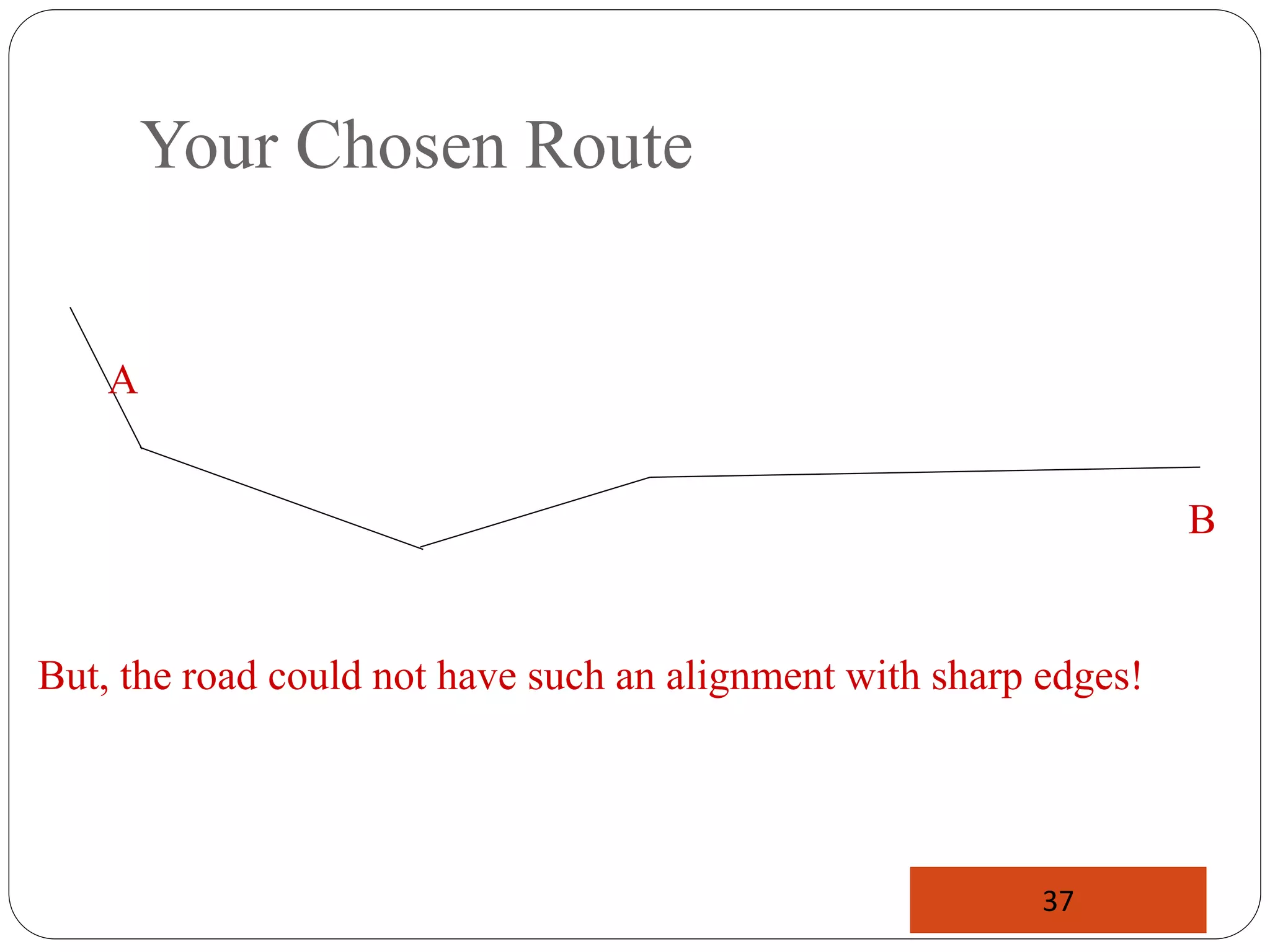
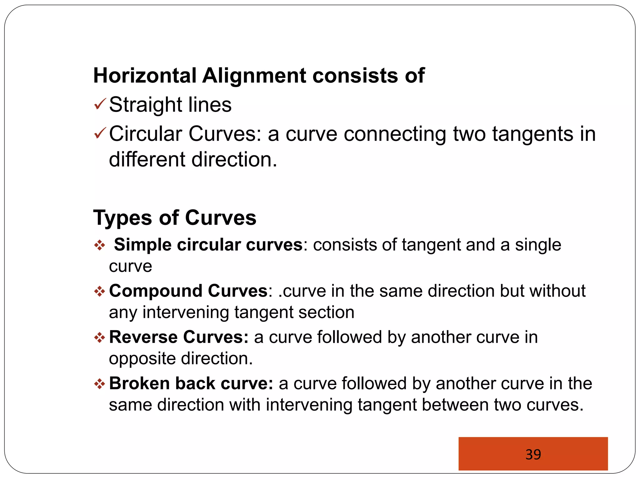
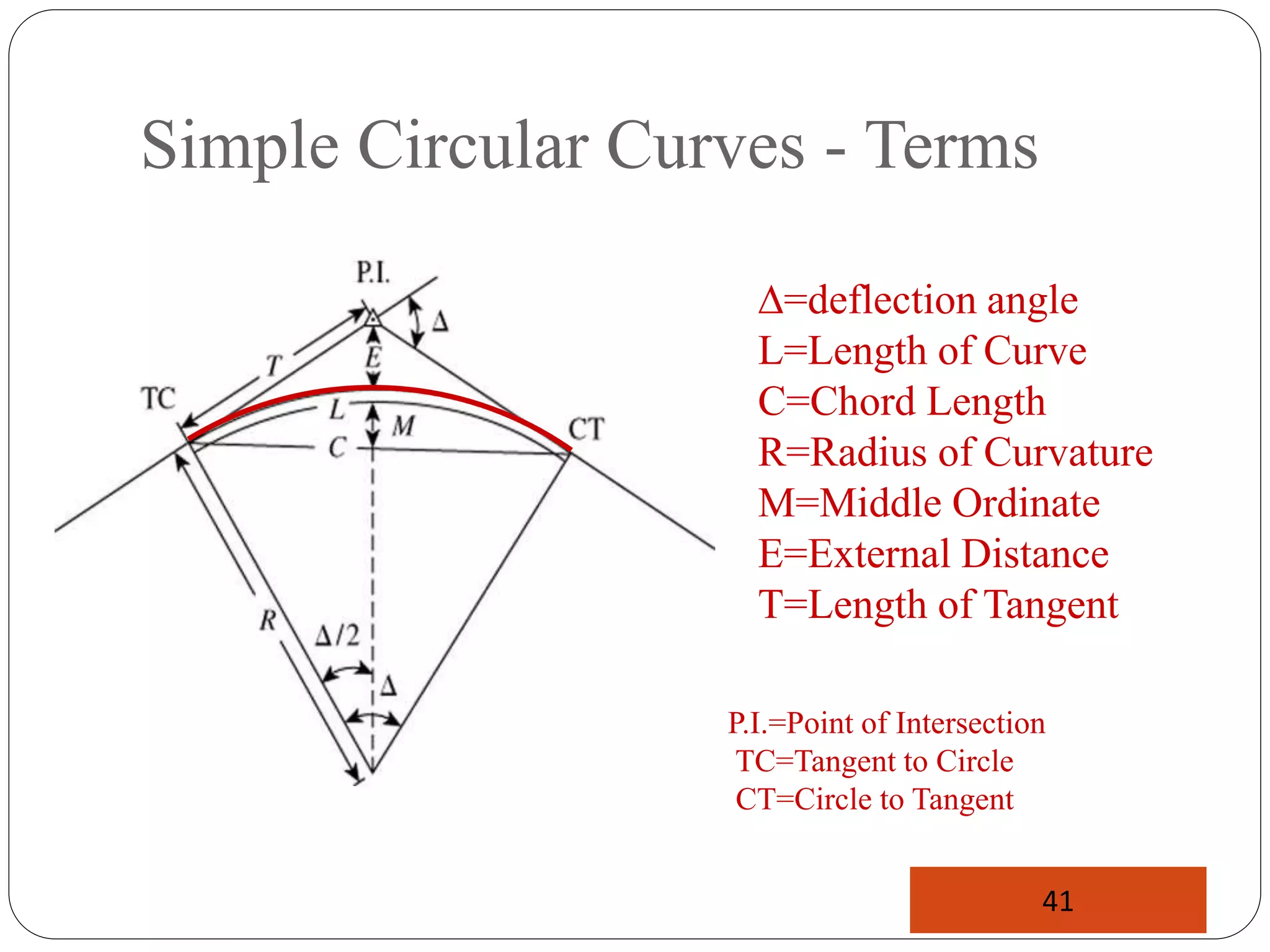
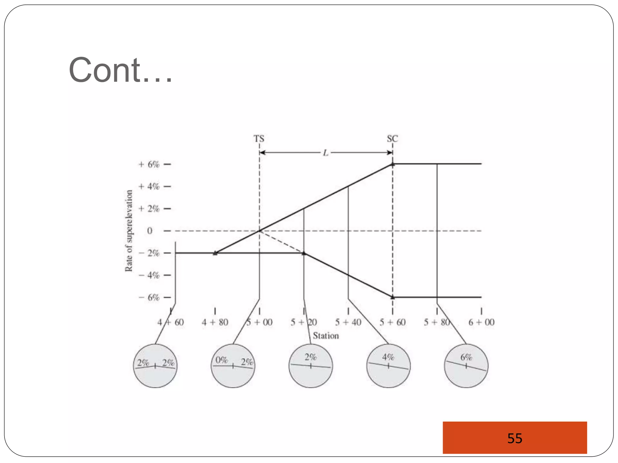
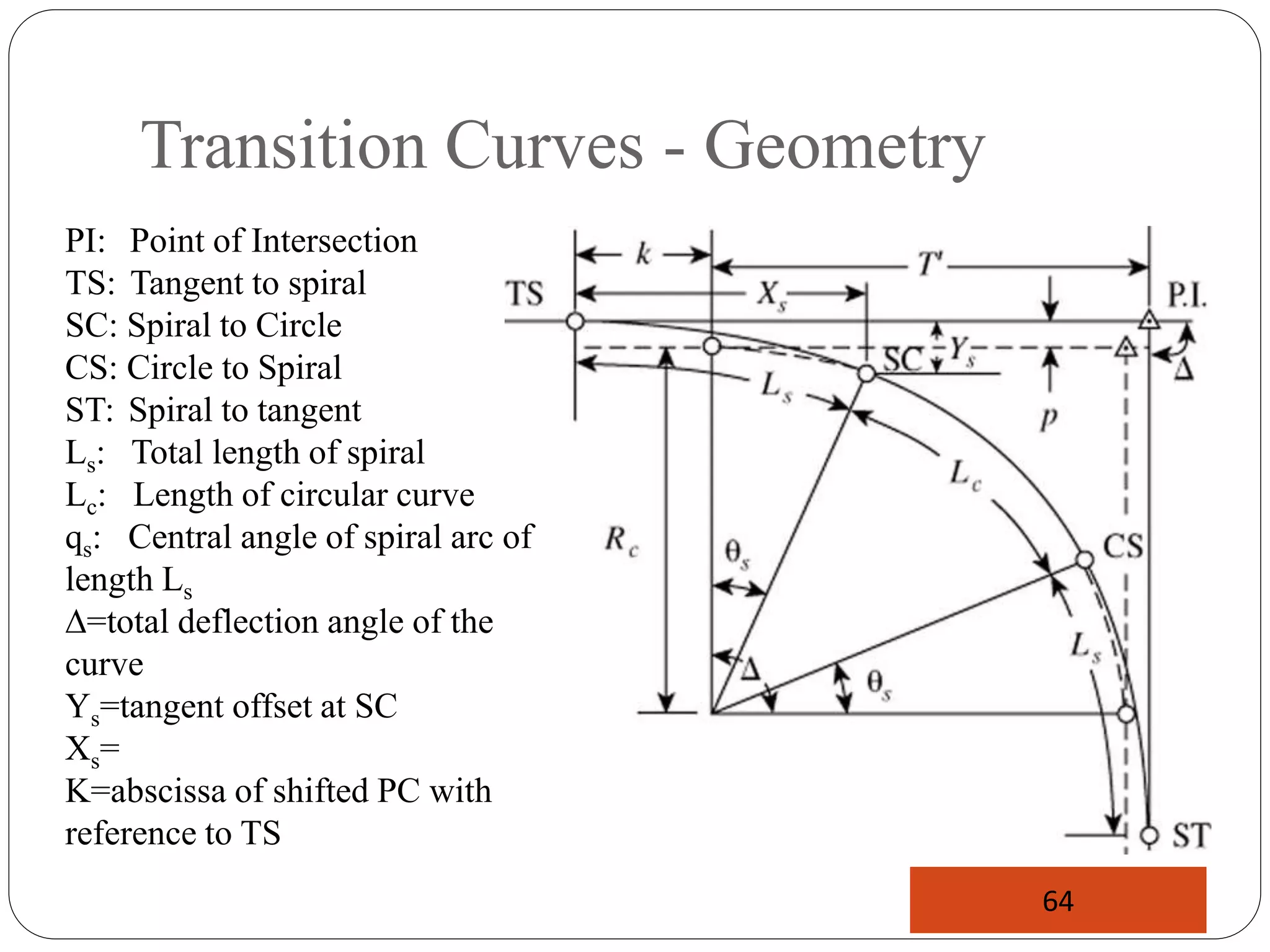
- Horizontal alignment connects straight sections and uses circular curves, which are classified as simple, compound, reverse, or broken back curves based on curvature