Downloaded 225 times
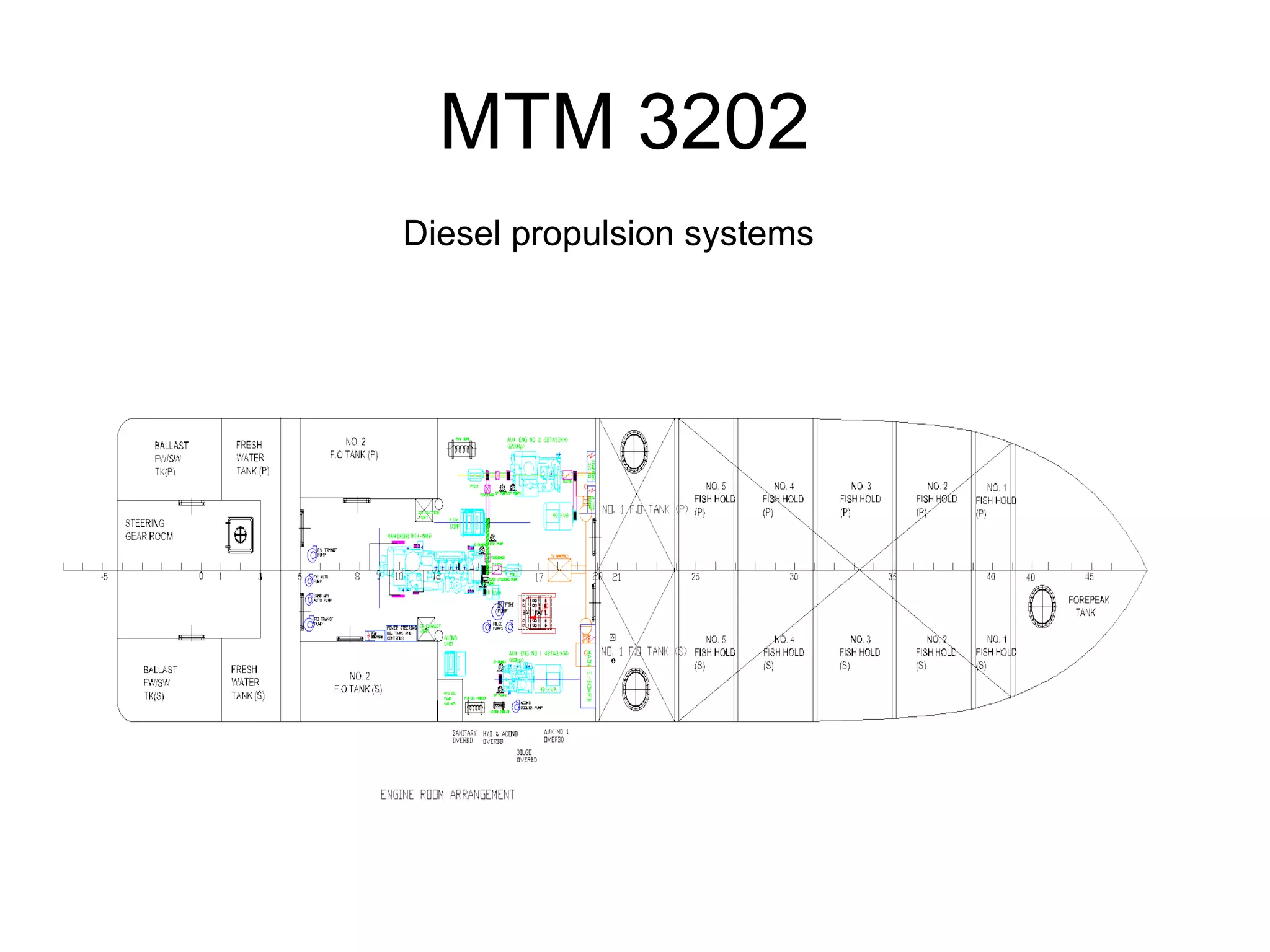
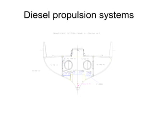
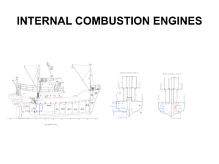
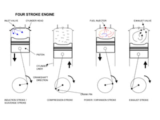
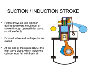
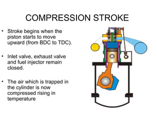
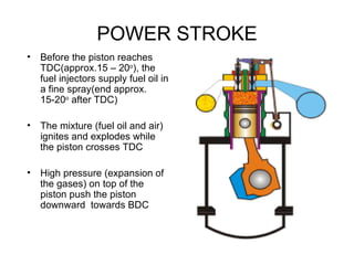
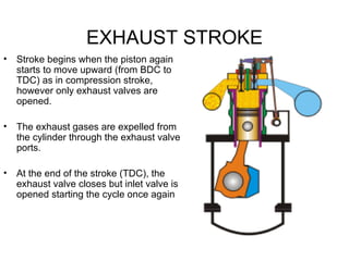
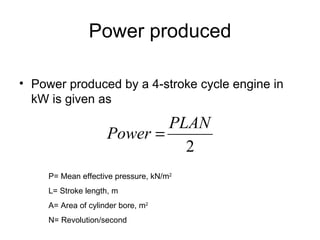
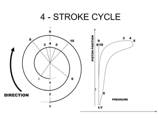
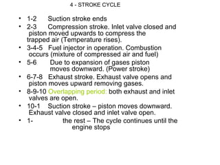
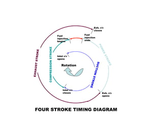
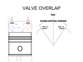
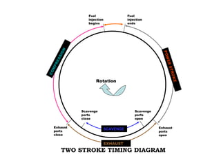


This document provides information on diesel propulsion systems and two-stroke diesel engines. It begins with learning objectives about familiarizing students with marine diesel engines. It then describes the operating cycles of internal combustion engines, including the Otto, Diesel, and dual cycles. It explains the four-stroke cycle and two-stroke cycle of compression ignition engines. Details are provided on the intake, compression, power, and exhaust strokes. The timing diagrams of the four-stroke and two-stroke cycles are illustrated. Valve timing and overlapping are also discussed.