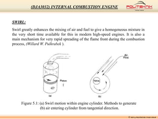
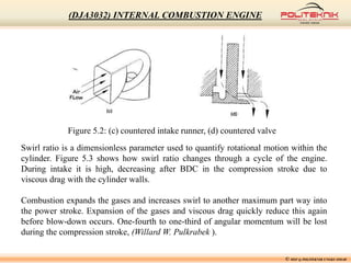
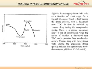
SlideShare a Scribd company logo
CHAPTER 5: FLUID MOTION IN
COMBUSTION CHAMBER AND EXHAUST FLOW
by
MOHD SAHRIL BIN MOHD FOUZI, Grad. IEM (G 27763)
DEPARTMENT OF MECHANICAL ENGINEERING
© MSF @ POLITEKNIK UNGKU OMAR
(DJA3032) INTERNAL COMBUSTION ENGINE
Introduction:
This chapter discusses air, fuel, and exhaust gas motion that occurs within the
cylinders during the compression stroke, combustion, and power stroke of the
cycle. It is important to have this motion to speed evaporation of the fuel, to
enhance air-fuel mixing, and to increase combustion speed and efficiency. In
addition to the normal desired turbulence, a rotational motion called swirl is
generated on the air-fuel mixture during intake.
Near the end of the compression stroke, two additional mass motions are generated:
squish and tumble. Squish is a radial motion towards the center-line of the cylinder,
while tumble is a rotational motion around a circumferential axis. One additional
flow motion will be discussed: that of crevice flow and blow-by. This is the flow
into the very small crevices of the combustion chamber due to the very high
pressures generated during compression and combustion,(Willard W. Pulkrabek ).
© MSF @ POLITEKNIK UNGKU OMAR
(DJA3032) INTERNAL COMBUSTION ENGINE
© MSF @ POLITEKNIK UNGKU OMAR
(DJA3032) INTERNAL COMBUSTION ENGINE
SWIRL:
Swirl greatly enhances the mixing of air and fuel to give a homogeneous mixture in
the very short time available for this in modern high-speed engines. It is also a
main mechanism for very rapid spreading of the flame front during the combustion
process, (Willard W. Pulkrabek ).
Figure 5.1: (a) Swirl motion within engine cylinder. Methods to generate
(b) air entering cylinder from tangential direction.
© MSF @ POLITEKNIK UNGKU OMAR
(DJA3032) INTERNAL COMBUSTION ENGINE
Figure 5.2: (c) countered intake runner, (d) countered valve
Swirl ratio is a dimensionless parameter used to quantify rotational motion within the
cylinder. Figure 5.3 shows how swirl ratio changes through a cycle of the engine.
During intake it is high, decreasing after BDC in the compression stroke due to
viscous drag with the cylinder walls.
Combustion expands the gases and increases swirl to another maximum part way into
the power stroke. Expansion of the gases and viscous drag quickly reduce this again
before blow-down occurs. One-fourth to one-third of angular momentum will be lost
during the compression stroke, (Willard W. Pulkrabek ).
© MSF @ POLITEKNIK UNGKU OMAR
(DJA3032) INTERNAL COMBUSTION ENGINE
Figure 5.3: Average cylinder swirl ratio
as a function of crank angle for a
typical SI engine. Swirl is high during
the intake process, with a maximum
near TDC. It then is reduced by
viscous drag during the compression
stroke. There is a second maximum
near ~e end of compression when the
radius of rotation is decreased near
TDC and expansion from combustion
occurs. Viscous drag with the cylinder
walls during the expansion stroke
quickly reduces this again before blow-
down occurs, (Willard W. Pulkrabek ).
© MSF @ POLITEKNIK UNGKU OMAR
(DJA3032) INTERNAL COMBUSTION ENGINE
TURBULENCE:
Due to the high velocities involved, all flows into, out of, and within engine
cylinders are turbulent flows. The exception to this are those flows in the corners and
small crevices of the combustion chamber where the close proximity of the walls
dampens out turbulence. As a result of turbulence, thermodynamic transfer rates
within an engine are increased by an order of magnitude.
When flow is turbulent, particles experience random fluctuations in motion
superimposed on their main bulk velocity. These fluctuations occur in all directions,
perpendicular to the flow and in the flow direction. This makes it impossible to
predict the exact flow conditions at any given time and position.
There are many levels of turbulence within an engine. Large-scale turbulence occurs
with eddies on the order of the size of the flow passage (e.g., valve opening,
diameter of intake runner, height of clearance volume, etc.),(Willard W. Pulkrabek ).
© MSF @ POLITEKNIK UNGKU OMAR
(DJA3032) INTERNAL COMBUSTION ENGINE
Turbulence in a cylinder is high during intake, but then decreases as the flow rate slows
near BDC. It increases again during compression as swirl, squish, and tumble increase
near TDC. Swirl makes turbulence more homogeneous throughout the cylinder.
The high turbulence near TDC when ignition occurs is very desirable for combustion. It
breaks up and spreads the flame front many times faster than that of a laminar flame.
The air-fuel is consumed in a very short time, and self-ignition and knock are avoided.
Local flame speed depends on the turbulence immediately in front of the flame. This
turbulence is enhanced by the expansion of the cylinder gases during the combustion
process. The shape of the combustion chamber is extremely important in generating
maximum turbulence and increasing the desired rapid combustion, (Willard W.
Pulkrabek ).
© MSF @ POLITEKNIK UNGKU OMAR
(DJA3032) INTERNAL COMBUSTION ENGINE
Figure 5.4: Turbulence level of gas flows in engines
as a function of engine speed.
Turbulence intensity is a strong function of engine speed (Fig. 5.4). As speed is
increased, turbulence increases, and this increases the rate of evaporation, mixing, and
combustion. One result of this is that all engine speeds have about the same burn angle
(i.e., the crank angle through which the engine turns as combustion takes place). The
one phase of this process which is not totally changed by the increase in turbulence is
ignition delay, (Willard W. Pulkrabek ).
© MSF @ POLITEKNIK UNGKU OMAR
(DJA3032) INTERNAL COMBUSTION ENGINE
SQUISH AND TUMBLE:
As the piston approaches TDC, the gas mixture occupying the volume at the outer
radius of the cylinder is forced radially inward as this outer volume is reduced to
near zero. This radial inward motion of the gas mixture is called squish. It adds to
other mass motions within the cylinder to mix the air and fuel, and to quickly spread
the flame front. Maximum squish velocity usually occurs at about 10° BTDC.
During combustion, the expansion stroke begins and the volume of the combustion
chamber increases. As the piston moves away from TDC, the burning gases are
propelled radially outward to fill the now-increasing outer volume along the cylinder.
walls. This reverse squish helps to spread the flame front during the latter part of
combustion.
As the piston nears TDC, squish motion generates a secondary rotational flow
called tumble. This rotation occurs about a circumferential axis near the outer edge
of the piston bowl as shown in Fig. 5.5, (Willard W. Pulkrabek ).
© MSF @ POLITEKNIK UNGKU OMAR
(DJA3032) INTERNAL COMBUSTION ENGINE
Figure 5.5: Tumble action caused by squish as piston
approaches TDC. Tumble is a rotational motion about a
circumferential axis near the edge of the clearance
volume in the piston bowl or in the cylinder head.
© MSF @ POLITEKNIK UNGKU OMAR
(DJA3032) INTERNAL COMBUSTION ENGINE
BLOWDOWN:
Exhaust blowdown occurs when the exhaust valve starts to open towards the end of
the power stroke, somewhere around 60° to 40° bBDC. At this time, pressure in the
cylinder is still at about 4-5 atmospheres and the temperature is upwards of 1000 K.
Pressure in the exhaust system is about one atmosphere, and when the valve is
opened the resulting pressure differential causes a rapid flow of exhaust gases from
the cylinder, through the valve, into the exhaust system (i.e., exhaust blowdown),
In an ideal air-standard Otto cycle or Diesel cycle, the exhaust valve opens at BDC
and blowdown occurs instantaneously at constant volume (process 4-5 in Fig. 5.6).
This does not happen in a real engine, where blowdown takes a finite length of time.
So that the pressure in the cylinder has been fully reduced by BDC when the exhaust
stroke starts, the exhaust valve starts to open somewhere around 60° to 40° bBDC.
When this happens, the pressure is quickly reduced, and what would have been
additional useful work is lost during the last part of the expansion stroke, (Willard W.
Pulkrabek ).
© MSF @ POLITEKNIK UNGKU OMAR
(DJA3032) INTERNAL COMBUSTION ENGINE
Figure 5.6: Air-standard Otto cycle in P-V coordinates
showing exhaust gas after blowdown at hypothetical state 7.
© MSF @ POLITEKNIK UNGKU OMAR
(DJA3032) INTERNAL COMBUSTION ENGINE
EXHAUST MANIFOLD:
After leaving the cylinders by passing out of the exhaust valves, exhaust gases pass
through the exhaust manifold, a piping system that directs the flow into one or more
exhaust pipes. Exhaust manifolds are usually made of cast iron and are sometimes
designed to have close thermal contact with the intake manifold. This is to provide
heating and vaporization in the intake manifold.
From the exhaust manifold, the gases flow through an exhaust pipe to the emission
control system of the engine, which may consist of thermal and/or catalytic
converters. One argument says these should be as close to the engine as space allows
to minimize heat losses. On the other hand, this creates high temperature problems in
the engine compartment. These converters promote reduction of emissions in the
exhaust gases by additional chemical reaction. They are discussed in the next
chapter, (Willard W. Pulkrabek ).
© MSF @ POLITEKNIK UNGKU OMAR
(DJA3032) INTERNAL COMBUSTION ENGINE
CATALYTIC CONVERTERS:
The most effective after treatment system for reducing engine emissions is the catalytic
converter found on most automobiles and other modern engines of medium or large
size. HC and CO can be oxidized to Hz 0 and COz in exhaust systems and thermal
converters if the temperature is held at 600°-700°C.
If certain catalysts are present, the temperature needed to sustain these oxidation
processes is reduced to 250°-300°C, making for a much more attractive system. A
catalyst is a substance that accelerates a chemical reaction by lowering the energy
needed for it to proceed. The catalyst is not consumed in the reaction and so functions
indefinitely unless degraded by heat, age, contaminants, or other factors.
Catalytic converters are chambers mounted in the flow system through which the
exhaust gases flow. These chambers contain catalytic material, which promotes the
oxidation of the emissions contained in the exhaust flow.
Generally, catalytic converters are called three-way converters because they promote the
reduction of CO, HC, and NOx. Most consist of a stainless steel container mounted
somewhere along the exhaust pipe of the engine. In most converters, the ceramic is a
single honeycomb structure with many flow passages, (Willard W. Pulkrabek ).
© MSF @ POLITEKNIK UNGKU OMAR
(DJA3032) INTERNAL COMBUSTION ENGINE
The surface of the ceramic passages contains small embedded particles of catalytic
material that promote the oxidation reactions in the exhaust gas as it passes. Aluminum
oxide (alumina) is the base ceramic material used for most catalytic converters.
Alumina can withstand the high temperatures, it remains chemically neutral, it has very
low thermal expansion, and it does not thermally degrade with age. The catalyst
materials most commonly used are platinum, palladium, and rhodium.
© MSF @ POLITEKNIK UNGKU OMAR
(DJA3032) INTERNAL COMBUSTION ENGINE
TAILPIPE AND MUFFLER:
After exiting the catalytic converter, exhaust gases flow through a tailpipe that ducts the
flow away from the passenger compartment of the vehicle and vents it to the
surroundings. This is usually under and out the back (or side) of an automobile and
often upward behind the cab of large trucks.
Somewhere in the tailpipe section there is usually a larger flow chamber called the
mumer. This is a sound chamber designed to reduce the operating noise of the engine,
most of which is carried out with the exhaust flow. Mufflers use two general methods of
sound reduction. One method absorbs the energy of sound pulses by flow through a
porous medium. Other mufflers reduce sound by the cancellation of waves. Instead of
fully dampening all engine noise, some mufflers are designed to give a louder, sporty
sound.
© MSF @ POLITEKNIK UNGKU OMAR
(DJA3032) INTERNAL COMBUSTION ENGINE

More Related Content

What's hot

CRDI ENGINE
CRDI ENGINE CRDI ENGINE
CRDI ENGINE
HOME
 
Turbo charger
Turbo chargerTurbo charger
Turbo charger
C Prathush
 
Complete guide to Internal Combustion engines (IC engines)
Complete guide to Internal Combustion engines (IC engines)Complete guide to Internal Combustion engines (IC engines)
Complete guide to Internal Combustion engines (IC engines)
Syed Yaseen
 
COMMON RAIL DIESEL INJECTION (CRDI;CRDe)
COMMON RAIL DIESEL INJECTION (CRDI;CRDe)COMMON RAIL DIESEL INJECTION (CRDI;CRDe)
COMMON RAIL DIESEL INJECTION (CRDI;CRDe)
Ananda Murugan M
 
Presentation on Petrol Engine
Presentation on Petrol Engine Presentation on Petrol Engine
Presentation on Petrol Engine
Ashraf Rizvi
 
i c engines efficiencies
i c engines efficienciesi c engines efficiencies
i c engines efficiencies
mp poonia
 
Turboprop
TurbopropTurboprop
Turboprop
kivancgunendi
 
FMP Fram Machinary And Power numericals
FMP Fram Machinary And Power numericalsFMP Fram Machinary And Power numericals
FMP Fram Machinary And Power numericals
Mehran Iqbal
 
4 stroke diesel engine
4 stroke diesel engine4 stroke diesel engine
4 stroke diesel engine
raxit varmora
 
Fluid couplin gppt
Fluid couplin gpptFluid couplin gppt
Fluid couplin gppt
Vikash Kumar
 
VERTICAL PRESSURE VESSEL DESIGN 5.docx
VERTICAL PRESSURE VESSEL DESIGN 5.docxVERTICAL PRESSURE VESSEL DESIGN 5.docx
VERTICAL PRESSURE VESSEL DESIGN 5.docx
TesemaTeshome
 
Variable speed hydraulic drive
Variable speed hydraulic driveVariable speed hydraulic drive
Variable speed hydraulic drivemitravanu mishra
 
Chapter 5 internal_combustion_engine
Chapter 5 internal_combustion_engineChapter 5 internal_combustion_engine
Chapter 5 internal_combustion_engine
Hashem Yahya Almahdi
 
Piston Engines: Operation
Piston Engines: OperationPiston Engines: Operation
Piston Engines: Operation
Jess Peters
 
IGNITION SYSTEM IN CARS
IGNITION SYSTEM IN CARSIGNITION SYSTEM IN CARS
IGNITION SYSTEM IN CARS
vishal gupta
 
Combustion in si engine
Combustion in si engineCombustion in si engine
Combustion in si engine
INDIAN INSTITUTE OF TECHNOLOGY Delhi
 
Air compressor
Air compressorAir compressor
Air compressor
sureshkcet
 
Variable valve timing in internal combustion engine
Variable valve timing in internal combustion engineVariable valve timing in internal combustion engine
Variable valve timing in internal combustion engine
risnathani
 
Wankel engine
Wankel engineWankel engine
Wankel engine
Amar Borkute
 
Turbocharging
TurbochargingTurbocharging
Turbocharging
Shubham Patel
 

What's hot (20)

CRDI ENGINE
CRDI ENGINE CRDI ENGINE
CRDI ENGINE
 
Turbo charger
Turbo chargerTurbo charger
Turbo charger
 
Complete guide to Internal Combustion engines (IC engines)
Complete guide to Internal Combustion engines (IC engines)Complete guide to Internal Combustion engines (IC engines)
Complete guide to Internal Combustion engines (IC engines)
 
COMMON RAIL DIESEL INJECTION (CRDI;CRDe)
COMMON RAIL DIESEL INJECTION (CRDI;CRDe)COMMON RAIL DIESEL INJECTION (CRDI;CRDe)
COMMON RAIL DIESEL INJECTION (CRDI;CRDe)
 
Presentation on Petrol Engine
Presentation on Petrol Engine Presentation on Petrol Engine
Presentation on Petrol Engine
 
i c engines efficiencies
i c engines efficienciesi c engines efficiencies
i c engines efficiencies
 
Turboprop
TurbopropTurboprop
Turboprop
 
FMP Fram Machinary And Power numericals
FMP Fram Machinary And Power numericalsFMP Fram Machinary And Power numericals
FMP Fram Machinary And Power numericals
 
4 stroke diesel engine
4 stroke diesel engine4 stroke diesel engine
4 stroke diesel engine
 
Fluid couplin gppt
Fluid couplin gpptFluid couplin gppt
Fluid couplin gppt
 
VERTICAL PRESSURE VESSEL DESIGN 5.docx
VERTICAL PRESSURE VESSEL DESIGN 5.docxVERTICAL PRESSURE VESSEL DESIGN 5.docx
VERTICAL PRESSURE VESSEL DESIGN 5.docx
 
Variable speed hydraulic drive
Variable speed hydraulic driveVariable speed hydraulic drive
Variable speed hydraulic drive
 
Chapter 5 internal_combustion_engine
Chapter 5 internal_combustion_engineChapter 5 internal_combustion_engine
Chapter 5 internal_combustion_engine
 
Piston Engines: Operation
Piston Engines: OperationPiston Engines: Operation
Piston Engines: Operation
 
IGNITION SYSTEM IN CARS
IGNITION SYSTEM IN CARSIGNITION SYSTEM IN CARS
IGNITION SYSTEM IN CARS
 
Combustion in si engine
Combustion in si engineCombustion in si engine
Combustion in si engine
 
Air compressor
Air compressorAir compressor
Air compressor
 
Variable valve timing in internal combustion engine
Variable valve timing in internal combustion engineVariable valve timing in internal combustion engine
Variable valve timing in internal combustion engine
 
Wankel engine
Wankel engineWankel engine
Wankel engine
 
Turbocharging
TurbochargingTurbocharging
Turbocharging
 

Viewers also liked

Internal combustion engine (ja304) chapter 4
Internal combustion engine (ja304) chapter 4Internal combustion engine (ja304) chapter 4
Internal combustion engine (ja304) chapter 4mechanical86
 
Internal combustion engine (ja304) chapter 2
Internal combustion engine (ja304) chapter 2Internal combustion engine (ja304) chapter 2
Internal combustion engine (ja304) chapter 2mechanical86
 
JA304 chapter 1
JA304 chapter 1JA304 chapter 1
JA304 chapter 1
mechanical86
 
INTERNAL COMBUSTION ENGINES PPT
INTERNAL COMBUSTION ENGINES PPT INTERNAL COMBUSTION ENGINES PPT
INTERNAL COMBUSTION ENGINES PPT
AKASH1001
 
Air-Motion in Engine Cylinder
Air-Motion in Engine CylinderAir-Motion in Engine Cylinder
Air-Motion in Engine Cylinder
Rajat Seth
 
Internal Combustion Engine & Gas Turbines
Internal Combustion Engine & Gas TurbinesInternal Combustion Engine & Gas Turbines
Internal Combustion Engine & Gas Turbines
FellowBuddy.com
 
Combustion Chambers
Combustion ChambersCombustion Chambers
Combustion Chambers
Rajat Seth
 
solution manual to basic and engineering thermodynamics by P K NAG 4th edition
solution manual to basic and engineering thermodynamics by P K NAG 4th editionsolution manual to basic and engineering thermodynamics by P K NAG 4th edition
solution manual to basic and engineering thermodynamics by P K NAG 4th edition
Chandu Kolli
 
3
33
Functional Fuels for Advanced Engine Technology
Functional Fuels for Advanced Engine TechnologyFunctional Fuels for Advanced Engine Technology
Functional Fuels for Advanced Engine Technology
Afton Chemical
 
heat engine information detail
heat engine information detailheat engine information detail
heat engine information detail
pratik darji
 
TANGENTIAL GROOVES IN PISTON CROWN FOR SWIRLING ACTION
TANGENTIAL GROOVES IN PISTON CROWN FOR SWIRLING ACTIONTANGENTIAL GROOVES IN PISTON CROWN FOR SWIRLING ACTION
TANGENTIAL GROOVES IN PISTON CROWN FOR SWIRLING ACTION
Kartik Paliwal
 
Measuring of different parameter of IC engine
Measuring of different parameter of IC engineMeasuring of different parameter of IC engine
Measuring of different parameter of IC engine
bhavesh patwa
 
Knocking & detonation
Knocking & detonationKnocking & detonation
Knocking & detonation
Qabool Ahmed Memon
 
ELECTRONIC FUEL INJECTOR
ELECTRONIC FUEL INJECTORELECTRONIC FUEL INJECTOR
ELECTRONIC FUEL INJECTOR
Debashish Bose
 
Moteurs thermiques alternatifs
Moteurs thermiques alternatifsMoteurs thermiques alternatifs
Moteurs thermiques alternatifszinoha
 
Combustion phenomenon in c.i engine
Combustion phenomenon in  c.i engineCombustion phenomenon in  c.i engine
Combustion phenomenon in c.i engineAjay Yedla
 

Viewers also liked (19)

Internal combustion engine (ja304) chapter 4
Internal combustion engine (ja304) chapter 4Internal combustion engine (ja304) chapter 4
Internal combustion engine (ja304) chapter 4
 
Internal combustion engine (ja304) chapter 2
Internal combustion engine (ja304) chapter 2Internal combustion engine (ja304) chapter 2
Internal combustion engine (ja304) chapter 2
 
JA304 chapter 1
JA304 chapter 1JA304 chapter 1
JA304 chapter 1
 
INTERNAL COMBUSTION ENGINES PPT
INTERNAL COMBUSTION ENGINES PPT INTERNAL COMBUSTION ENGINES PPT
INTERNAL COMBUSTION ENGINES PPT
 
Air-Motion in Engine Cylinder
Air-Motion in Engine CylinderAir-Motion in Engine Cylinder
Air-Motion in Engine Cylinder
 
Internal Combustion Engine & Gas Turbines
Internal Combustion Engine & Gas TurbinesInternal Combustion Engine & Gas Turbines
Internal Combustion Engine & Gas Turbines
 
Combustion Chambers
Combustion ChambersCombustion Chambers
Combustion Chambers
 
solution manual to basic and engineering thermodynamics by P K NAG 4th edition
solution manual to basic and engineering thermodynamics by P K NAG 4th editionsolution manual to basic and engineering thermodynamics by P K NAG 4th edition
solution manual to basic and engineering thermodynamics by P K NAG 4th edition
 
3
33
3
 
Functional Fuels for Advanced Engine Technology
Functional Fuels for Advanced Engine TechnologyFunctional Fuels for Advanced Engine Technology
Functional Fuels for Advanced Engine Technology
 
heat engine information detail
heat engine information detailheat engine information detail
heat engine information detail
 
Session 34 Per Stålhammar
Session 34 Per StålhammarSession 34 Per Stålhammar
Session 34 Per Stålhammar
 
TANGENTIAL GROOVES IN PISTON CROWN FOR SWIRLING ACTION
TANGENTIAL GROOVES IN PISTON CROWN FOR SWIRLING ACTIONTANGENTIAL GROOVES IN PISTON CROWN FOR SWIRLING ACTION
TANGENTIAL GROOVES IN PISTON CROWN FOR SWIRLING ACTION
 
Measuring of different parameter of IC engine
Measuring of different parameter of IC engineMeasuring of different parameter of IC engine
Measuring of different parameter of IC engine
 
Knocking & detonation
Knocking & detonationKnocking & detonation
Knocking & detonation
 
ELECTRONIC FUEL INJECTOR
ELECTRONIC FUEL INJECTORELECTRONIC FUEL INJECTOR
ELECTRONIC FUEL INJECTOR
 
Moteurs thermiques alternatifs
Moteurs thermiques alternatifsMoteurs thermiques alternatifs
Moteurs thermiques alternatifs
 
Combustion phenomenon in c.i engine
Combustion phenomenon in  c.i engineCombustion phenomenon in  c.i engine
Combustion phenomenon in c.i engine
 
Detonation
DetonationDetonation
Detonation
 

Similar to DJA3032 CHAPTER 5

A Critical Review on the Concept of Effect on Scavenging and Fuel Injection T...
A Critical Review on the Concept of Effect on Scavenging and Fuel Injection T...A Critical Review on the Concept of Effect on Scavenging and Fuel Injection T...
A Critical Review on the Concept of Effect on Scavenging and Fuel Injection T...
ijsrd.com
 
engines
enginesengines
engines
Senthil Kumar
 
Design and Analysis of the Effect of a Modified Valve with Helical Guideways ...
Design and Analysis of the Effect of a Modified Valve with Helical Guideways ...Design and Analysis of the Effect of a Modified Valve with Helical Guideways ...
Design and Analysis of the Effect of a Modified Valve with Helical Guideways ...
IJERA Editor
 
Combustion in Internal Combustion (IC) Engines
Combustion in Internal Combustion (IC) EnginesCombustion in Internal Combustion (IC) Engines
Combustion in Internal Combustion (IC) Engines
iMentor Education
 
4 stroke petrol engine
4 stroke petrol engine4 stroke petrol engine
4 stroke petrol engine
HarisRiaz25
 
Four stoke engines
Four stoke enginesFour stoke engines
Four stoke engines
JIBRIN HABIBU
 
Fundamental of ic engine by asnh
Fundamental of ic engine by asnhFundamental of ic engine by asnh
Fundamental of ic engine by asnh
Avesahemad Husainy
 
Thermodynamicsbycengelandyunuscimbalpladean
ThermodynamicsbycengelandyunuscimbalpladeanThermodynamicsbycengelandyunuscimbalpladean
Thermodynamicsbycengelandyunuscimbalpladean
David850003
 
Chapter 1 internal combustion engine
Chapter 1 internal combustion engineChapter 1 internal combustion engine
Chapter 1 internal combustion engine
Muhd Taufik Muhammad
 
Chapter 2 - Force Induction System.pptx
Chapter 2 - Force Induction System.pptxChapter 2 - Force Induction System.pptx
Chapter 2 - Force Induction System.pptx
NemoKoh
 
SCUDERI SPLIT CYCLE ENGINE: REVOLUTIONARY TECHNOLOGY & EVOLUTIONARY DESIGN RE...
SCUDERI SPLIT CYCLE ENGINE: REVOLUTIONARY TECHNOLOGY & EVOLUTIONARY DESIGN RE...SCUDERI SPLIT CYCLE ENGINE: REVOLUTIONARY TECHNOLOGY & EVOLUTIONARY DESIGN RE...
SCUDERI SPLIT CYCLE ENGINE: REVOLUTIONARY TECHNOLOGY & EVOLUTIONARY DESIGN RE...
ijiert bestjournal
 
To Study the Properties of Self Compacting Concrete Using Recycled Aggregate ...
To Study the Properties of Self Compacting Concrete Using Recycled Aggregate ...To Study the Properties of Self Compacting Concrete Using Recycled Aggregate ...
To Study the Properties of Self Compacting Concrete Using Recycled Aggregate ...
paperpublications3
 
Study of Tumble Measurement on a Steady State Flow Rig
Study of Tumble Measurement on a Steady State Flow RigStudy of Tumble Measurement on a Steady State Flow Rig
Study of Tumble Measurement on a Steady State Flow Rig
paperpublications3
 
Six stroke engine using gasoline and r 123
Six stroke engine using gasoline and r 123Six stroke engine using gasoline and r 123
Six stroke engine using gasoline and r 123
eSAT Journals
 
A COMPREHENSIVE REVIEW ON COMBUSTION OF COMPRESSION IGNITION ENGINES USING BI...
A COMPREHENSIVE REVIEW ON COMBUSTION OF COMPRESSION IGNITION ENGINES USING BI...A COMPREHENSIVE REVIEW ON COMBUSTION OF COMPRESSION IGNITION ENGINES USING BI...
A COMPREHENSIVE REVIEW ON COMBUSTION OF COMPRESSION IGNITION ENGINES USING BI...
IAEME Publication
 
Power plant engineering
Power plant engineeringPower plant engineering
Power plant engineering
india
 
A report on Diesel Power Plant
A report on Diesel Power PlantA report on Diesel Power Plant
A report on Diesel Power Plant
Sangeeth Soman
 
Vikash Kr Mahato9(sharda university) Presentation on ic engine
Vikash Kr Mahato9(sharda university) Presentation on ic engineVikash Kr Mahato9(sharda university) Presentation on ic engine
Vikash Kr Mahato9(sharda university) Presentation on ic engine
Dude I'm still student
 
12000721061.pdf
12000721061.pdf12000721061.pdf
12000721061.pdf
SubhojitDas48
 

Similar to DJA3032 CHAPTER 5 (20)

A Critical Review on the Concept of Effect on Scavenging and Fuel Injection T...
A Critical Review on the Concept of Effect on Scavenging and Fuel Injection T...A Critical Review on the Concept of Effect on Scavenging and Fuel Injection T...
A Critical Review on the Concept of Effect on Scavenging and Fuel Injection T...
 
engines
enginesengines
engines
 
Design and Analysis of the Effect of a Modified Valve with Helical Guideways ...
Design and Analysis of the Effect of a Modified Valve with Helical Guideways ...Design and Analysis of the Effect of a Modified Valve with Helical Guideways ...
Design and Analysis of the Effect of a Modified Valve with Helical Guideways ...
 
Combustion in Internal Combustion (IC) Engines
Combustion in Internal Combustion (IC) EnginesCombustion in Internal Combustion (IC) Engines
Combustion in Internal Combustion (IC) Engines
 
4 stroke petrol engine
4 stroke petrol engine4 stroke petrol engine
4 stroke petrol engine
 
Conceptos basicos
Conceptos basicosConceptos basicos
Conceptos basicos
 
Four stoke engines
Four stoke enginesFour stoke engines
Four stoke engines
 
Fundamental of ic engine by asnh
Fundamental of ic engine by asnhFundamental of ic engine by asnh
Fundamental of ic engine by asnh
 
Thermodynamicsbycengelandyunuscimbalpladean
ThermodynamicsbycengelandyunuscimbalpladeanThermodynamicsbycengelandyunuscimbalpladean
Thermodynamicsbycengelandyunuscimbalpladean
 
Chapter 1 internal combustion engine
Chapter 1 internal combustion engineChapter 1 internal combustion engine
Chapter 1 internal combustion engine
 
Chapter 2 - Force Induction System.pptx
Chapter 2 - Force Induction System.pptxChapter 2 - Force Induction System.pptx
Chapter 2 - Force Induction System.pptx
 
SCUDERI SPLIT CYCLE ENGINE: REVOLUTIONARY TECHNOLOGY & EVOLUTIONARY DESIGN RE...
SCUDERI SPLIT CYCLE ENGINE: REVOLUTIONARY TECHNOLOGY & EVOLUTIONARY DESIGN RE...SCUDERI SPLIT CYCLE ENGINE: REVOLUTIONARY TECHNOLOGY & EVOLUTIONARY DESIGN RE...
SCUDERI SPLIT CYCLE ENGINE: REVOLUTIONARY TECHNOLOGY & EVOLUTIONARY DESIGN RE...
 
To Study the Properties of Self Compacting Concrete Using Recycled Aggregate ...
To Study the Properties of Self Compacting Concrete Using Recycled Aggregate ...To Study the Properties of Self Compacting Concrete Using Recycled Aggregate ...
To Study the Properties of Self Compacting Concrete Using Recycled Aggregate ...
 
Study of Tumble Measurement on a Steady State Flow Rig
Study of Tumble Measurement on a Steady State Flow RigStudy of Tumble Measurement on a Steady State Flow Rig
Study of Tumble Measurement on a Steady State Flow Rig
 
Six stroke engine using gasoline and r 123
Six stroke engine using gasoline and r 123Six stroke engine using gasoline and r 123
Six stroke engine using gasoline and r 123
 
A COMPREHENSIVE REVIEW ON COMBUSTION OF COMPRESSION IGNITION ENGINES USING BI...
A COMPREHENSIVE REVIEW ON COMBUSTION OF COMPRESSION IGNITION ENGINES USING BI...A COMPREHENSIVE REVIEW ON COMBUSTION OF COMPRESSION IGNITION ENGINES USING BI...
A COMPREHENSIVE REVIEW ON COMBUSTION OF COMPRESSION IGNITION ENGINES USING BI...
 
Power plant engineering
Power plant engineeringPower plant engineering
Power plant engineering
 
A report on Diesel Power Plant
A report on Diesel Power PlantA report on Diesel Power Plant
A report on Diesel Power Plant
 
Vikash Kr Mahato9(sharda university) Presentation on ic engine
Vikash Kr Mahato9(sharda university) Presentation on ic engineVikash Kr Mahato9(sharda university) Presentation on ic engine
Vikash Kr Mahato9(sharda university) Presentation on ic engine
 
12000721061.pdf
12000721061.pdf12000721061.pdf
12000721061.pdf
 

Recently uploaded

Lapbook sobre os Regimes Totalitários.pdf
Lapbook sobre os Regimes Totalitários.pdfLapbook sobre os Regimes Totalitários.pdf
Lapbook sobre os Regimes Totalitários.pdf
Jean Carlos Nunes Paixão
 
TESDA TM1 REVIEWER FOR NATIONAL ASSESSMENT WRITTEN AND ORAL QUESTIONS WITH A...
TESDA TM1 REVIEWER  FOR NATIONAL ASSESSMENT WRITTEN AND ORAL QUESTIONS WITH A...TESDA TM1 REVIEWER  FOR NATIONAL ASSESSMENT WRITTEN AND ORAL QUESTIONS WITH A...
TESDA TM1 REVIEWER FOR NATIONAL ASSESSMENT WRITTEN AND ORAL QUESTIONS WITH A...
EugeneSaldivar
 
The basics of sentences session 5pptx.pptx
The basics of sentences session 5pptx.pptxThe basics of sentences session 5pptx.pptx
The basics of sentences session 5pptx.pptx
heathfieldcps1
 
Digital Artifact 1 - 10VCD Environments Unit
Digital Artifact 1 - 10VCD Environments UnitDigital Artifact 1 - 10VCD Environments Unit
Digital Artifact 1 - 10VCD Environments Unit
chanes7
 
Group Presentation 2 Economics.Ariana Buscigliopptx
Group Presentation 2 Economics.Ariana BuscigliopptxGroup Presentation 2 Economics.Ariana Buscigliopptx
Group Presentation 2 Economics.Ariana Buscigliopptx
ArianaBusciglio
 
Unit 2- Research Aptitude (UGC NET Paper I).pdf
Unit 2- Research Aptitude (UGC NET Paper I).pdfUnit 2- Research Aptitude (UGC NET Paper I).pdf
Unit 2- Research Aptitude (UGC NET Paper I).pdf
Thiyagu K
 
Natural birth techniques - Mrs.Akanksha Trivedi Rama University
Natural birth techniques - Mrs.Akanksha Trivedi Rama UniversityNatural birth techniques - Mrs.Akanksha Trivedi Rama University
Natural birth techniques - Mrs.Akanksha Trivedi Rama University
Akanksha trivedi rama nursing college kanpur.
 
World environment day ppt For 5 June 2024
World environment day ppt For 5 June 2024World environment day ppt For 5 June 2024
World environment day ppt For 5 June 2024
ak6969907
 
Azure Interview Questions and Answers PDF By ScholarHat
Azure Interview Questions and Answers PDF By ScholarHatAzure Interview Questions and Answers PDF By ScholarHat
Azure Interview Questions and Answers PDF By ScholarHat
Scholarhat
 
RPMS TEMPLATE FOR SCHOOL YEAR 2023-2024 FOR TEACHER 1 TO TEACHER 3
RPMS TEMPLATE FOR SCHOOL YEAR 2023-2024 FOR TEACHER 1 TO TEACHER 3RPMS TEMPLATE FOR SCHOOL YEAR 2023-2024 FOR TEACHER 1 TO TEACHER 3
RPMS TEMPLATE FOR SCHOOL YEAR 2023-2024 FOR TEACHER 1 TO TEACHER 3
IreneSebastianRueco1
 
Digital Artefact 1 - Tiny Home Environmental Design
Digital Artefact 1 - Tiny Home Environmental DesignDigital Artefact 1 - Tiny Home Environmental Design
Digital Artefact 1 - Tiny Home Environmental Design
amberjdewit93
 
S1-Introduction-Biopesticides in ICM.pptx
S1-Introduction-Biopesticides in ICM.pptxS1-Introduction-Biopesticides in ICM.pptx
S1-Introduction-Biopesticides in ICM.pptx
tarandeep35
 
PIMS Job Advertisement 2024.pdf Islamabad
PIMS Job Advertisement 2024.pdf IslamabadPIMS Job Advertisement 2024.pdf Islamabad
PIMS Job Advertisement 2024.pdf Islamabad
AyyanKhan40
 
Thesis Statement for students diagnonsed withADHD.ppt
Thesis Statement for students diagnonsed withADHD.pptThesis Statement for students diagnonsed withADHD.ppt
Thesis Statement for students diagnonsed withADHD.ppt
EverAndrsGuerraGuerr
 
Landownership in the Philippines under the Americans-2-pptx.pptx
Landownership in the Philippines under the Americans-2-pptx.pptxLandownership in the Philippines under the Americans-2-pptx.pptx
Landownership in the Philippines under the Americans-2-pptx.pptx
JezreelCabil2
 
Unit 8 - Information and Communication Technology (Paper I).pdf
Unit 8 - Information and Communication Technology (Paper I).pdfUnit 8 - Information and Communication Technology (Paper I).pdf
Unit 8 - Information and Communication Technology (Paper I).pdf
Thiyagu K
 
Executive Directors Chat Leveraging AI for Diversity, Equity, and Inclusion
Executive Directors Chat  Leveraging AI for Diversity, Equity, and InclusionExecutive Directors Chat  Leveraging AI for Diversity, Equity, and Inclusion
Executive Directors Chat Leveraging AI for Diversity, Equity, and Inclusion
TechSoup
 
"Protectable subject matters, Protection in biotechnology, Protection of othe...
"Protectable subject matters, Protection in biotechnology, Protection of othe..."Protectable subject matters, Protection in biotechnology, Protection of othe...
"Protectable subject matters, Protection in biotechnology, Protection of othe...
SACHIN R KONDAGURI
 
Exploiting Artificial Intelligence for Empowering Researchers and Faculty, In...
Exploiting Artificial Intelligence for Empowering Researchers and Faculty, In...Exploiting Artificial Intelligence for Empowering Researchers and Faculty, In...
Exploiting Artificial Intelligence for Empowering Researchers and Faculty, In...
Dr. Vinod Kumar Kanvaria
 
CACJapan - GROUP Presentation 1- Wk 4.pdf
CACJapan - GROUP Presentation 1- Wk 4.pdfCACJapan - GROUP Presentation 1- Wk 4.pdf
CACJapan - GROUP Presentation 1- Wk 4.pdf
camakaiclarkmusic
 

Recently uploaded (20)

Lapbook sobre os Regimes Totalitários.pdf
Lapbook sobre os Regimes Totalitários.pdfLapbook sobre os Regimes Totalitários.pdf
Lapbook sobre os Regimes Totalitários.pdf
 
TESDA TM1 REVIEWER FOR NATIONAL ASSESSMENT WRITTEN AND ORAL QUESTIONS WITH A...
TESDA TM1 REVIEWER  FOR NATIONAL ASSESSMENT WRITTEN AND ORAL QUESTIONS WITH A...TESDA TM1 REVIEWER  FOR NATIONAL ASSESSMENT WRITTEN AND ORAL QUESTIONS WITH A...
TESDA TM1 REVIEWER FOR NATIONAL ASSESSMENT WRITTEN AND ORAL QUESTIONS WITH A...
 
The basics of sentences session 5pptx.pptx
The basics of sentences session 5pptx.pptxThe basics of sentences session 5pptx.pptx
The basics of sentences session 5pptx.pptx
 
Digital Artifact 1 - 10VCD Environments Unit
Digital Artifact 1 - 10VCD Environments UnitDigital Artifact 1 - 10VCD Environments Unit
Digital Artifact 1 - 10VCD Environments Unit
 
Group Presentation 2 Economics.Ariana Buscigliopptx
Group Presentation 2 Economics.Ariana BuscigliopptxGroup Presentation 2 Economics.Ariana Buscigliopptx
Group Presentation 2 Economics.Ariana Buscigliopptx
 
Unit 2- Research Aptitude (UGC NET Paper I).pdf
Unit 2- Research Aptitude (UGC NET Paper I).pdfUnit 2- Research Aptitude (UGC NET Paper I).pdf
Unit 2- Research Aptitude (UGC NET Paper I).pdf
 
Natural birth techniques - Mrs.Akanksha Trivedi Rama University
Natural birth techniques - Mrs.Akanksha Trivedi Rama UniversityNatural birth techniques - Mrs.Akanksha Trivedi Rama University
Natural birth techniques - Mrs.Akanksha Trivedi Rama University
 
World environment day ppt For 5 June 2024
World environment day ppt For 5 June 2024World environment day ppt For 5 June 2024
World environment day ppt For 5 June 2024
 
Azure Interview Questions and Answers PDF By ScholarHat
Azure Interview Questions and Answers PDF By ScholarHatAzure Interview Questions and Answers PDF By ScholarHat
Azure Interview Questions and Answers PDF By ScholarHat
 
RPMS TEMPLATE FOR SCHOOL YEAR 2023-2024 FOR TEACHER 1 TO TEACHER 3
RPMS TEMPLATE FOR SCHOOL YEAR 2023-2024 FOR TEACHER 1 TO TEACHER 3RPMS TEMPLATE FOR SCHOOL YEAR 2023-2024 FOR TEACHER 1 TO TEACHER 3
RPMS TEMPLATE FOR SCHOOL YEAR 2023-2024 FOR TEACHER 1 TO TEACHER 3
 
Digital Artefact 1 - Tiny Home Environmental Design
Digital Artefact 1 - Tiny Home Environmental DesignDigital Artefact 1 - Tiny Home Environmental Design
Digital Artefact 1 - Tiny Home Environmental Design
 
S1-Introduction-Biopesticides in ICM.pptx
S1-Introduction-Biopesticides in ICM.pptxS1-Introduction-Biopesticides in ICM.pptx
S1-Introduction-Biopesticides in ICM.pptx
 
PIMS Job Advertisement 2024.pdf Islamabad
PIMS Job Advertisement 2024.pdf IslamabadPIMS Job Advertisement 2024.pdf Islamabad
PIMS Job Advertisement 2024.pdf Islamabad
 
Thesis Statement for students diagnonsed withADHD.ppt
Thesis Statement for students diagnonsed withADHD.pptThesis Statement for students diagnonsed withADHD.ppt
Thesis Statement for students diagnonsed withADHD.ppt
 
Landownership in the Philippines under the Americans-2-pptx.pptx
Landownership in the Philippines under the Americans-2-pptx.pptxLandownership in the Philippines under the Americans-2-pptx.pptx
Landownership in the Philippines under the Americans-2-pptx.pptx
 
Unit 8 - Information and Communication Technology (Paper I).pdf
Unit 8 - Information and Communication Technology (Paper I).pdfUnit 8 - Information and Communication Technology (Paper I).pdf
Unit 8 - Information and Communication Technology (Paper I).pdf
 
Executive Directors Chat Leveraging AI for Diversity, Equity, and Inclusion
Executive Directors Chat  Leveraging AI for Diversity, Equity, and InclusionExecutive Directors Chat  Leveraging AI for Diversity, Equity, and Inclusion
Executive Directors Chat Leveraging AI for Diversity, Equity, and Inclusion
 
"Protectable subject matters, Protection in biotechnology, Protection of othe...
"Protectable subject matters, Protection in biotechnology, Protection of othe..."Protectable subject matters, Protection in biotechnology, Protection of othe...
"Protectable subject matters, Protection in biotechnology, Protection of othe...
 
Exploiting Artificial Intelligence for Empowering Researchers and Faculty, In...
Exploiting Artificial Intelligence for Empowering Researchers and Faculty, In...Exploiting Artificial Intelligence for Empowering Researchers and Faculty, In...
Exploiting Artificial Intelligence for Empowering Researchers and Faculty, In...
 
CACJapan - GROUP Presentation 1- Wk 4.pdf
CACJapan - GROUP Presentation 1- Wk 4.pdfCACJapan - GROUP Presentation 1- Wk 4.pdf
CACJapan - GROUP Presentation 1- Wk 4.pdf
 

DJA3032 CHAPTER 5

  • 1. CHAPTER 5: FLUID MOTION IN COMBUSTION CHAMBER AND EXHAUST FLOW by MOHD SAHRIL BIN MOHD FOUZI, Grad. IEM (G 27763) DEPARTMENT OF MECHANICAL ENGINEERING © MSF @ POLITEKNIK UNGKU OMAR (DJA3032) INTERNAL COMBUSTION ENGINE
  • 2. Introduction: This chapter discusses air, fuel, and exhaust gas motion that occurs within the cylinders during the compression stroke, combustion, and power stroke of the cycle. It is important to have this motion to speed evaporation of the fuel, to enhance air-fuel mixing, and to increase combustion speed and efficiency. In addition to the normal desired turbulence, a rotational motion called swirl is generated on the air-fuel mixture during intake. Near the end of the compression stroke, two additional mass motions are generated: squish and tumble. Squish is a radial motion towards the center-line of the cylinder, while tumble is a rotational motion around a circumferential axis. One additional flow motion will be discussed: that of crevice flow and blow-by. This is the flow into the very small crevices of the combustion chamber due to the very high pressures generated during compression and combustion,(Willard W. Pulkrabek ). © MSF @ POLITEKNIK UNGKU OMAR (DJA3032) INTERNAL COMBUSTION ENGINE
  • 3. © MSF @ POLITEKNIK UNGKU OMAR (DJA3032) INTERNAL COMBUSTION ENGINE SWIRL: Swirl greatly enhances the mixing of air and fuel to give a homogeneous mixture in the very short time available for this in modern high-speed engines. It is also a main mechanism for very rapid spreading of the flame front during the combustion process, (Willard W. Pulkrabek ). Figure 5.1: (a) Swirl motion within engine cylinder. Methods to generate (b) air entering cylinder from tangential direction.
  • 4. © MSF @ POLITEKNIK UNGKU OMAR (DJA3032) INTERNAL COMBUSTION ENGINE Figure 5.2: (c) countered intake runner, (d) countered valve Swirl ratio is a dimensionless parameter used to quantify rotational motion within the cylinder. Figure 5.3 shows how swirl ratio changes through a cycle of the engine. During intake it is high, decreasing after BDC in the compression stroke due to viscous drag with the cylinder walls. Combustion expands the gases and increases swirl to another maximum part way into the power stroke. Expansion of the gases and viscous drag quickly reduce this again before blow-down occurs. One-fourth to one-third of angular momentum will be lost during the compression stroke, (Willard W. Pulkrabek ).
  • 5. © MSF @ POLITEKNIK UNGKU OMAR (DJA3032) INTERNAL COMBUSTION ENGINE Figure 5.3: Average cylinder swirl ratio as a function of crank angle for a typical SI engine. Swirl is high during the intake process, with a maximum near TDC. It then is reduced by viscous drag during the compression stroke. There is a second maximum near ~e end of compression when the radius of rotation is decreased near TDC and expansion from combustion occurs. Viscous drag with the cylinder walls during the expansion stroke quickly reduces this again before blow- down occurs, (Willard W. Pulkrabek ).
  • 6. © MSF @ POLITEKNIK UNGKU OMAR (DJA3032) INTERNAL COMBUSTION ENGINE TURBULENCE: Due to the high velocities involved, all flows into, out of, and within engine cylinders are turbulent flows. The exception to this are those flows in the corners and small crevices of the combustion chamber where the close proximity of the walls dampens out turbulence. As a result of turbulence, thermodynamic transfer rates within an engine are increased by an order of magnitude. When flow is turbulent, particles experience random fluctuations in motion superimposed on their main bulk velocity. These fluctuations occur in all directions, perpendicular to the flow and in the flow direction. This makes it impossible to predict the exact flow conditions at any given time and position. There are many levels of turbulence within an engine. Large-scale turbulence occurs with eddies on the order of the size of the flow passage (e.g., valve opening, diameter of intake runner, height of clearance volume, etc.),(Willard W. Pulkrabek ).
  • 7. © MSF @ POLITEKNIK UNGKU OMAR (DJA3032) INTERNAL COMBUSTION ENGINE Turbulence in a cylinder is high during intake, but then decreases as the flow rate slows near BDC. It increases again during compression as swirl, squish, and tumble increase near TDC. Swirl makes turbulence more homogeneous throughout the cylinder. The high turbulence near TDC when ignition occurs is very desirable for combustion. It breaks up and spreads the flame front many times faster than that of a laminar flame. The air-fuel is consumed in a very short time, and self-ignition and knock are avoided. Local flame speed depends on the turbulence immediately in front of the flame. This turbulence is enhanced by the expansion of the cylinder gases during the combustion process. The shape of the combustion chamber is extremely important in generating maximum turbulence and increasing the desired rapid combustion, (Willard W. Pulkrabek ).
  • 8. © MSF @ POLITEKNIK UNGKU OMAR (DJA3032) INTERNAL COMBUSTION ENGINE Figure 5.4: Turbulence level of gas flows in engines as a function of engine speed. Turbulence intensity is a strong function of engine speed (Fig. 5.4). As speed is increased, turbulence increases, and this increases the rate of evaporation, mixing, and combustion. One result of this is that all engine speeds have about the same burn angle (i.e., the crank angle through which the engine turns as combustion takes place). The one phase of this process which is not totally changed by the increase in turbulence is ignition delay, (Willard W. Pulkrabek ).
  • 9. © MSF @ POLITEKNIK UNGKU OMAR (DJA3032) INTERNAL COMBUSTION ENGINE SQUISH AND TUMBLE: As the piston approaches TDC, the gas mixture occupying the volume at the outer radius of the cylinder is forced radially inward as this outer volume is reduced to near zero. This radial inward motion of the gas mixture is called squish. It adds to other mass motions within the cylinder to mix the air and fuel, and to quickly spread the flame front. Maximum squish velocity usually occurs at about 10° BTDC. During combustion, the expansion stroke begins and the volume of the combustion chamber increases. As the piston moves away from TDC, the burning gases are propelled radially outward to fill the now-increasing outer volume along the cylinder. walls. This reverse squish helps to spread the flame front during the latter part of combustion. As the piston nears TDC, squish motion generates a secondary rotational flow called tumble. This rotation occurs about a circumferential axis near the outer edge of the piston bowl as shown in Fig. 5.5, (Willard W. Pulkrabek ).
  • 10. © MSF @ POLITEKNIK UNGKU OMAR (DJA3032) INTERNAL COMBUSTION ENGINE Figure 5.5: Tumble action caused by squish as piston approaches TDC. Tumble is a rotational motion about a circumferential axis near the edge of the clearance volume in the piston bowl or in the cylinder head.
  • 11. © MSF @ POLITEKNIK UNGKU OMAR (DJA3032) INTERNAL COMBUSTION ENGINE BLOWDOWN: Exhaust blowdown occurs when the exhaust valve starts to open towards the end of the power stroke, somewhere around 60° to 40° bBDC. At this time, pressure in the cylinder is still at about 4-5 atmospheres and the temperature is upwards of 1000 K. Pressure in the exhaust system is about one atmosphere, and when the valve is opened the resulting pressure differential causes a rapid flow of exhaust gases from the cylinder, through the valve, into the exhaust system (i.e., exhaust blowdown), In an ideal air-standard Otto cycle or Diesel cycle, the exhaust valve opens at BDC and blowdown occurs instantaneously at constant volume (process 4-5 in Fig. 5.6). This does not happen in a real engine, where blowdown takes a finite length of time. So that the pressure in the cylinder has been fully reduced by BDC when the exhaust stroke starts, the exhaust valve starts to open somewhere around 60° to 40° bBDC. When this happens, the pressure is quickly reduced, and what would have been additional useful work is lost during the last part of the expansion stroke, (Willard W. Pulkrabek ).
  • 12. © MSF @ POLITEKNIK UNGKU OMAR (DJA3032) INTERNAL COMBUSTION ENGINE Figure 5.6: Air-standard Otto cycle in P-V coordinates showing exhaust gas after blowdown at hypothetical state 7.
  • 13. © MSF @ POLITEKNIK UNGKU OMAR (DJA3032) INTERNAL COMBUSTION ENGINE EXHAUST MANIFOLD: After leaving the cylinders by passing out of the exhaust valves, exhaust gases pass through the exhaust manifold, a piping system that directs the flow into one or more exhaust pipes. Exhaust manifolds are usually made of cast iron and are sometimes designed to have close thermal contact with the intake manifold. This is to provide heating and vaporization in the intake manifold. From the exhaust manifold, the gases flow through an exhaust pipe to the emission control system of the engine, which may consist of thermal and/or catalytic converters. One argument says these should be as close to the engine as space allows to minimize heat losses. On the other hand, this creates high temperature problems in the engine compartment. These converters promote reduction of emissions in the exhaust gases by additional chemical reaction. They are discussed in the next chapter, (Willard W. Pulkrabek ).
  • 14. © MSF @ POLITEKNIK UNGKU OMAR (DJA3032) INTERNAL COMBUSTION ENGINE CATALYTIC CONVERTERS: The most effective after treatment system for reducing engine emissions is the catalytic converter found on most automobiles and other modern engines of medium or large size. HC and CO can be oxidized to Hz 0 and COz in exhaust systems and thermal converters if the temperature is held at 600°-700°C. If certain catalysts are present, the temperature needed to sustain these oxidation processes is reduced to 250°-300°C, making for a much more attractive system. A catalyst is a substance that accelerates a chemical reaction by lowering the energy needed for it to proceed. The catalyst is not consumed in the reaction and so functions indefinitely unless degraded by heat, age, contaminants, or other factors. Catalytic converters are chambers mounted in the flow system through which the exhaust gases flow. These chambers contain catalytic material, which promotes the oxidation of the emissions contained in the exhaust flow. Generally, catalytic converters are called three-way converters because they promote the reduction of CO, HC, and NOx. Most consist of a stainless steel container mounted somewhere along the exhaust pipe of the engine. In most converters, the ceramic is a single honeycomb structure with many flow passages, (Willard W. Pulkrabek ).
  • 15. © MSF @ POLITEKNIK UNGKU OMAR (DJA3032) INTERNAL COMBUSTION ENGINE The surface of the ceramic passages contains small embedded particles of catalytic material that promote the oxidation reactions in the exhaust gas as it passes. Aluminum oxide (alumina) is the base ceramic material used for most catalytic converters. Alumina can withstand the high temperatures, it remains chemically neutral, it has very low thermal expansion, and it does not thermally degrade with age. The catalyst materials most commonly used are platinum, palladium, and rhodium.
  • 16. © MSF @ POLITEKNIK UNGKU OMAR (DJA3032) INTERNAL COMBUSTION ENGINE TAILPIPE AND MUFFLER: After exiting the catalytic converter, exhaust gases flow through a tailpipe that ducts the flow away from the passenger compartment of the vehicle and vents it to the surroundings. This is usually under and out the back (or side) of an automobile and often upward behind the cab of large trucks. Somewhere in the tailpipe section there is usually a larger flow chamber called the mumer. This is a sound chamber designed to reduce the operating noise of the engine, most of which is carried out with the exhaust flow. Mufflers use two general methods of sound reduction. One method absorbs the energy of sound pulses by flow through a porous medium. Other mufflers reduce sound by the cancellation of waves. Instead of fully dampening all engine noise, some mufflers are designed to give a louder, sporty sound.
  • 17. © MSF @ POLITEKNIK UNGKU OMAR (DJA3032) INTERNAL COMBUSTION ENGINE