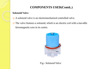
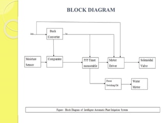
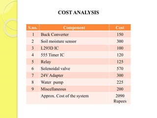
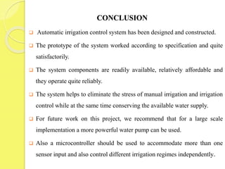
A
presentation
on
INTELLIGENT AUTOMATIC PLANT IRRIGATION SYSTEM
Guide Presented by
Mr. Sunny Kumar Paswan Deepesh Kumar Dubey
Faculty, Electronics Deptt. Ram Babu Gupta
I.E.T. Lucknow Susheel Kumar
CONTENTS
 Introduction
 Components used
 Block Diagram
 Working Principal
 Advantage
 Disadvantage
 Application
 Cost analysis
 Conclusion
 References
INTRODUCTION
 Irrigation is an artificial supplying of water to the root of plant.
 The old method used for irrigation was the use of watering cans, water
channels that have to be opened and closed manually or backpack
sprinklers.
 In this case, a lot of water is wasted in the process.
 An automated irrigation system needs to be developed to optimize water
use for agricultural crops.
 An intelligent automatic irrigation system has to have all the components
that autonomously monitor and control the level of water available to the
plants without any failure or human intervention.
COMPONENTS USED
 Buck Converter
 Moisture Sensor
 Comparator
 NE 555 Timer
 Motor Driver IC ( L293D )
 Solenoid Valve
 Relay
 Water Motor
 Resistors ( 10K, 1K, 1M)
 Capacitors
 Light Emitting Diode
COMPONENTS USED (Contd...)
Buck Converter:- A buck converter (step-down converter) is a DC-to-DC
power converter which steps down voltage (while stepping up current)
from its input (supply) to its output (load).
Fig:- Buck Converter
COMPONENTS USED(Contd..)
Soil Moisture Sensor
 The Soil Moisture Sensor is a simple breakout for measuring the moisture in
soil and similar materials.
 The two large exposed pads function as probes for the sensor, together acting
as a variable resistor.
 The more water that is in the soil means the better the conductivity between
the probes will be and will result in a lower resistance, and a higher
conductivity.
Fig:- Soil moisture sensor
COMPONENTS USED(Contd..)
Comparator
 The Op-amp comparator compares one analogue voltage level with
another analogue voltage level, or some preset reference voltage.
Fig:- Comparator
COMPONENTS USED(Contd..)
NE555 Timer IC
The 555 Timer is a simple timer to generate single pulses or long time
delays, or as a relaxation oscillator producing stabilized waveforms of
varying duty cycles from 50 to 100%.
Fig.3.4:- NE555 Timer
COMPONENTS USED(Contd..)
Motor Driver
 Here L293D IC is used as motor driver.
 It is used here to drive three solenoid valve.
Fig:- L293D pin diagram
COMPONENTS USED(Contd..)
Solenoid Valve
 A solenoid valve is an electromechanical controlled valve.
 The valve features a solenoid, which is an electric coil with a movable
ferromagnetic core in its centre.
Fig:- Solenoid Valve
BLOCK DIAGRAM
WORKING PRINCIPLE
 When the soil is dry the resistivity of the soil increases and current
flowing between probes of moisture sensor decreases.
 This leads to less voltage sensed at non-inverting terminal than inverting
terminal of comparator.
 The output pin of the op-amp is connected to the pin no.2 of NE555
timer.
 A positive pulse of time duration 1.1RC is generated at the output of 555
timer.
 The output of 555 timer is connected to the motor driver input pin as well
as to the relay circuit which switch on the water motor as well as
solenoidal valve.
ADVANTAGES
 Highly sensitive
 Works according to the soil condition
 Fit and Forget system
 Low cost and reliable circuit
 Complete elimination of manpower
 System can be switched into manual mode whenever required.
Disadvantages
 There are costs in purchasing, installing and maintaining automatic
equipment.
 Sometimes failures will occur.
 There is a need to increase maintenance of channels and equipment to
ensure the system works correctly.
APPLICATIONS
 Roof Gardens
 Lawns
 Agriculture Lands
 Home Gardens
COST ANALYSIS
S.no. Component Cost
1 Buck Converter 150
2 Soil moisture sensor 300
3 L293D IC 100
4 555 Timer IC 120
5 Relay 125
6 Solenoidal valve 570
7 24V Adapter 300
8 Water pump 225
9 Miscellaneous 200
Approx. Cost of the system 2090
Rupees
CONCLUSION
 Automatic irrigation control system has been designed and constructed.
 The prototype of the system worked according to specification and quite
satisfactorily.
 The system components are readily available, relatively affordable and
they operate quite reliably.
 The system helps to eliminate the stress of manual irrigation and irrigation
control while at the same time conserving the available water supply.
 For future work on this project, we recommend that for a large scale
implementation a more powerful water pump can be used.
 Also a microcontroller should be used to accommodate more than one
sensor input and also control different irrigation regimes independently.
REFERENCES
[1].Pavithra D.S, Srinath M.S “GSM based automatic irrigation control system
for efficient use of resources and crop planning by using an Android
mobile” IOSR Journal of Mechanical and Civil Engineering Volume 11,
Issue 4 Ver.1 July-August 2014 p. 49-55.
[2]. Abhinav Rajpal, Sumit Jain, Nistha Khare and Anil Kumar Shukla
“Microcontroller-based Automatic Irrigation System with Moisture Sensor”
Proceedings of the International Conference on Science and Engineerin
(ICSE 2011).
[3]. Gutierrez J, Villa-medina, J,F, Nieto- Garibay, A. and Porta-Gandara, M.A
Journal of Instrumentation and Measurement, IEEE Transactions Volume 63
Issue 1, p. 166-176
[4]. Qiuming K.; Yandong Z.; Chenxiang B.: “Automatic monitor and control
system of water saving irrigation”, Transactions of the Chinese Society of
Agricultural Engineering, Vol. 2007 no.6, Society of Agricultural
Engineering.
THANK YOU

Intelligent Automatic Plant Irrigation System

  • 1.
    A presentation on INTELLIGENT AUTOMATIC PLANTIRRIGATION SYSTEM Guide Presented by Mr. Sunny Kumar Paswan Deepesh Kumar Dubey Faculty, Electronics Deptt. Ram Babu Gupta I.E.T. Lucknow Susheel Kumar
  • 2.
    CONTENTS  Introduction  Componentsused  Block Diagram  Working Principal  Advantage  Disadvantage  Application  Cost analysis  Conclusion  References
  • 3.
    INTRODUCTION  Irrigation isan artificial supplying of water to the root of plant.  The old method used for irrigation was the use of watering cans, water channels that have to be opened and closed manually or backpack sprinklers.  In this case, a lot of water is wasted in the process.  An automated irrigation system needs to be developed to optimize water use for agricultural crops.  An intelligent automatic irrigation system has to have all the components that autonomously monitor and control the level of water available to the plants without any failure or human intervention.
  • 4.
    COMPONENTS USED  BuckConverter  Moisture Sensor  Comparator  NE 555 Timer  Motor Driver IC ( L293D )  Solenoid Valve  Relay  Water Motor  Resistors ( 10K, 1K, 1M)  Capacitors  Light Emitting Diode
  • 5.
    COMPONENTS USED (Contd...) BuckConverter:- A buck converter (step-down converter) is a DC-to-DC power converter which steps down voltage (while stepping up current) from its input (supply) to its output (load). Fig:- Buck Converter
  • 6.
    COMPONENTS USED(Contd..) Soil MoistureSensor  The Soil Moisture Sensor is a simple breakout for measuring the moisture in soil and similar materials.  The two large exposed pads function as probes for the sensor, together acting as a variable resistor.  The more water that is in the soil means the better the conductivity between the probes will be and will result in a lower resistance, and a higher conductivity. Fig:- Soil moisture sensor
  • 7.
    COMPONENTS USED(Contd..) Comparator  TheOp-amp comparator compares one analogue voltage level with another analogue voltage level, or some preset reference voltage. Fig:- Comparator
  • 8.
    COMPONENTS USED(Contd..) NE555 TimerIC The 555 Timer is a simple timer to generate single pulses or long time delays, or as a relaxation oscillator producing stabilized waveforms of varying duty cycles from 50 to 100%. Fig.3.4:- NE555 Timer
  • 9.
    COMPONENTS USED(Contd..) Motor Driver Here L293D IC is used as motor driver.  It is used here to drive three solenoid valve. Fig:- L293D pin diagram
  • 10.
    COMPONENTS USED(Contd..) Solenoid Valve A solenoid valve is an electromechanical controlled valve.  The valve features a solenoid, which is an electric coil with a movable ferromagnetic core in its centre. Fig:- Solenoid Valve
  • 11.
  • 12.
    WORKING PRINCIPLE  Whenthe soil is dry the resistivity of the soil increases and current flowing between probes of moisture sensor decreases.  This leads to less voltage sensed at non-inverting terminal than inverting terminal of comparator.  The output pin of the op-amp is connected to the pin no.2 of NE555 timer.  A positive pulse of time duration 1.1RC is generated at the output of 555 timer.  The output of 555 timer is connected to the motor driver input pin as well as to the relay circuit which switch on the water motor as well as solenoidal valve.
  • 13.
    ADVANTAGES  Highly sensitive Works according to the soil condition  Fit and Forget system  Low cost and reliable circuit  Complete elimination of manpower  System can be switched into manual mode whenever required.
  • 14.
    Disadvantages  There arecosts in purchasing, installing and maintaining automatic equipment.  Sometimes failures will occur.  There is a need to increase maintenance of channels and equipment to ensure the system works correctly.
  • 15.
    APPLICATIONS  Roof Gardens Lawns  Agriculture Lands  Home Gardens
  • 16.
    COST ANALYSIS S.no. ComponentCost 1 Buck Converter 150 2 Soil moisture sensor 300 3 L293D IC 100 4 555 Timer IC 120 5 Relay 125 6 Solenoidal valve 570 7 24V Adapter 300 8 Water pump 225 9 Miscellaneous 200 Approx. Cost of the system 2090 Rupees
  • 17.
    CONCLUSION  Automatic irrigationcontrol system has been designed and constructed.  The prototype of the system worked according to specification and quite satisfactorily.  The system components are readily available, relatively affordable and they operate quite reliably.  The system helps to eliminate the stress of manual irrigation and irrigation control while at the same time conserving the available water supply.  For future work on this project, we recommend that for a large scale implementation a more powerful water pump can be used.  Also a microcontroller should be used to accommodate more than one sensor input and also control different irrigation regimes independently.
  • 18.
    REFERENCES [1].Pavithra D.S, SrinathM.S “GSM based automatic irrigation control system for efficient use of resources and crop planning by using an Android mobile” IOSR Journal of Mechanical and Civil Engineering Volume 11, Issue 4 Ver.1 July-August 2014 p. 49-55. [2]. Abhinav Rajpal, Sumit Jain, Nistha Khare and Anil Kumar Shukla “Microcontroller-based Automatic Irrigation System with Moisture Sensor” Proceedings of the International Conference on Science and Engineerin (ICSE 2011). [3]. Gutierrez J, Villa-medina, J,F, Nieto- Garibay, A. and Porta-Gandara, M.A Journal of Instrumentation and Measurement, IEEE Transactions Volume 63 Issue 1, p. 166-176 [4]. Qiuming K.; Yandong Z.; Chenxiang B.: “Automatic monitor and control system of water saving irrigation”, Transactions of the Chinese Society of Agricultural Engineering, Vol. 2007 no.6, Society of Agricultural Engineering.
  • 19.