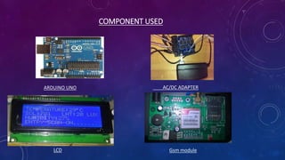
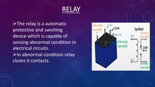
AUTOMATIC PLANT WATERING
SYSTEM
SUBMITTED BY:-
ABHISHEK AWASTHI
GUIDED BY:-
MR.DEVENDRA SINGH
CONTENTS
Introduction
Components used
PCB Designing
Block diagram
Circuit diagram
Working
Advantages
Disadvantage
Application
Future expansion
Conclusion
INTRODUCTION
Irrigation is an artificial supplying of water to the root ofplant.
In old methods, a lot of water is wasted in the process.
In a country like India, where the economy is mainly based on agriculture and
the climatic conditions are isotropic, still we are not able to make full use of
agricultural resources.
At the present era, the farmers have been using irrigation techniques in India
through manual control in which farmers irrigate the land at the regular
intervals.
Some of the sophisticated crops require fixed temperature ,light and other
factors which are satisfied using different techniques.
COMPONENT USED
ARDUINO UNO AC/DC ADAPTER
LCD Gsm module
Soil Moisture Sensor HUMIDITY SENSOR
Relay
Ultrasonic sensor
LDR
TUBE LIGHT WATER PUMP
FAN
WATER SPRINKLER BUZZER
Resistor LEDs Potentiometer
DiodeTransistor
PCB DESIGNING
PROCESSING
CLEANING
PRINTING
ETCHING
DRILLING
SOLDERING
MASKING
BLOCK DIAGRAM
ARDUINO
HUMIDITY
SENSOR
LDR
LCD
MOISTURE
SENSOR
RELAY DRIVER
RELAY DRIVER
JET MOTOR
ULTRA SONIC
SENSOR
POWER SUPPLY
RELAY DRIVER
RELAY DRIVER RELAY
RELAY
RELAY
RELAY
FAN
TUBE LIGHT
PUMP
BUZZER
Gsm module
CIRCUIT DIAGRAM
Uses capacitance to measured the water
content.
Accuracy :±5%
Operating temperature is 40 to 60 degree
celcius.
SOIL & MOISTURE SENSORS
LCD
20*4 LCD
20*4 LCD means max. 20
characters per line can be
displayed and there are two
lines.
Provide interface for inputting
or selecting.
Economical,easily
programmable
LDR
 LDR is a light dependent
resistor which indicate the
presence or absence of light.
At dark=1Mohm
light=1kohm
Follows photoconductivity
principle.
RELAY
The relay is a automatic
protective and swiching
device which is capable of
sensing abnormal condition in
electrical circuits.
In abnormal condition relay
closes it contacts.
ULTRASONIC SENSOR
triggerecho
obstacle
Trigger signal
Echo signal
HUMIDITY SENSOR
• Humidity sensor senses
,measures the relative
humidity in the air .
• Supply voltage : +5 v
• Temperature Range: 0-50
C.
• Humidity : 20-90%.
WORKING
This project uses Arduino Uno to controls the motor. The
Arduino Board is programmed using the Arduino IDE software.
The moisture sensor measures the level of moisture in the soil
and sent the signal to the Arduino if watering is required.
Relay driver circuit is on/off by the Arduino signal.
Relay circuit regulate the pump operation.
The water pump supplies water to the plants until the desired
moisture level is reached.
GSM module sent the message to user that motor will be
on/off.
• Humidity Sensor measures both air temperature and moisture. When
humidity changes from a predefined value then sensor senses the
changes and send signal to the Arduino.
• Relay Driver circuit regulate the water sprinkler and fan .
• GSM Module send the message to the user that jet or fan is on//off.
• LDR measures the light intensity and if less than predefined value then
sends signal to the Arduino.
• Relay driver circuit then regulate the operation of tube light.
• GSM Module send message to the user that tube light is on/off.
• LCD display all the operation occurring in the system and also display
the value obtained from various sensors
ADVANTAGES
Reduce the wastage of water.
Reduce the human intervention.
Fit and forget system.
Work according to the soil condition.
Highly sensitive.
DISADVANTAGES
•Sometimes failures may occur.
•Expensive due to cost of installing and maintaining
the automatic equipment.
APPLICATION
Roof of garden.
Lawn
Agriculture land.
Green city buildings.
Home gardens.
Indoor farming(vertical farming).
Green building Indoor farming
MODERN TRENDS
FUTURE EXPANSION
In future we can add the esp module to get the
real time information of system.
Also biometric & password protected system can
be added in future to start the system.
CONCLUSION
In cities it is difficult to maintain the life of plants during working
hours and in vacations when going outside.
In present days, especially farmers are facing major problems in
watering their agriculture fields, it’s because they have no proper
idea of when the power is available so that they can pump water.
Even after then they need to wait until the field is properly
watered, which makes them stop doing other activities.
Here is an idea that helps not only farmers even for watering the
gardens also, which senses the soil moisture and switches the
pump automatically when the power is ON.
Some sophisticated crops require different weather conditions
which are fulfilled from this techniques.
So automatic watering system is very useful.
automatic irrigation system ppt

automatic irrigation system ppt

  • 1.
    AUTOMATIC PLANT WATERING SYSTEM SUBMITTEDBY:- ABHISHEK AWASTHI GUIDED BY:- MR.DEVENDRA SINGH
  • 2.
    CONTENTS Introduction Components used PCB Designing Blockdiagram Circuit diagram Working Advantages Disadvantage Application Future expansion Conclusion
  • 3.
    INTRODUCTION Irrigation is anartificial supplying of water to the root ofplant. In old methods, a lot of water is wasted in the process. In a country like India, where the economy is mainly based on agriculture and the climatic conditions are isotropic, still we are not able to make full use of agricultural resources. At the present era, the farmers have been using irrigation techniques in India through manual control in which farmers irrigate the land at the regular intervals. Some of the sophisticated crops require fixed temperature ,light and other factors which are satisfied using different techniques.
  • 4.
    COMPONENT USED ARDUINO UNOAC/DC ADAPTER LCD Gsm module
  • 5.
    Soil Moisture SensorHUMIDITY SENSOR Relay Ultrasonic sensor LDR
  • 6.
    TUBE LIGHT WATERPUMP FAN WATER SPRINKLER BUZZER
  • 7.
  • 8.
  • 9.
    BLOCK DIAGRAM ARDUINO HUMIDITY SENSOR LDR LCD MOISTURE SENSOR RELAY DRIVER RELAYDRIVER JET MOTOR ULTRA SONIC SENSOR POWER SUPPLY RELAY DRIVER RELAY DRIVER RELAY RELAY RELAY RELAY FAN TUBE LIGHT PUMP BUZZER Gsm module
  • 10.
  • 11.
    Uses capacitance tomeasured the water content. Accuracy :±5% Operating temperature is 40 to 60 degree celcius. SOIL & MOISTURE SENSORS
  • 12.
    LCD 20*4 LCD 20*4 LCDmeans max. 20 characters per line can be displayed and there are two lines. Provide interface for inputting or selecting. Economical,easily programmable
  • 13.
    LDR  LDR isa light dependent resistor which indicate the presence or absence of light. At dark=1Mohm light=1kohm Follows photoconductivity principle.
  • 14.
    RELAY The relay isa automatic protective and swiching device which is capable of sensing abnormal condition in electrical circuits. In abnormal condition relay closes it contacts.
  • 15.
  • 16.
    HUMIDITY SENSOR • Humiditysensor senses ,measures the relative humidity in the air . • Supply voltage : +5 v • Temperature Range: 0-50 C. • Humidity : 20-90%.
  • 17.
    WORKING This project usesArduino Uno to controls the motor. The Arduino Board is programmed using the Arduino IDE software. The moisture sensor measures the level of moisture in the soil and sent the signal to the Arduino if watering is required. Relay driver circuit is on/off by the Arduino signal. Relay circuit regulate the pump operation. The water pump supplies water to the plants until the desired moisture level is reached. GSM module sent the message to user that motor will be on/off.
  • 18.
    • Humidity Sensormeasures both air temperature and moisture. When humidity changes from a predefined value then sensor senses the changes and send signal to the Arduino. • Relay Driver circuit regulate the water sprinkler and fan . • GSM Module send the message to the user that jet or fan is on//off. • LDR measures the light intensity and if less than predefined value then sends signal to the Arduino. • Relay driver circuit then regulate the operation of tube light. • GSM Module send message to the user that tube light is on/off. • LCD display all the operation occurring in the system and also display the value obtained from various sensors
  • 19.
    ADVANTAGES Reduce the wastageof water. Reduce the human intervention. Fit and forget system. Work according to the soil condition. Highly sensitive.
  • 20.
    DISADVANTAGES •Sometimes failures mayoccur. •Expensive due to cost of installing and maintaining the automatic equipment.
  • 21.
    APPLICATION Roof of garden. Lawn Agricultureland. Green city buildings. Home gardens. Indoor farming(vertical farming).
  • 22.
    Green building Indoorfarming MODERN TRENDS
  • 23.
    FUTURE EXPANSION In futurewe can add the esp module to get the real time information of system. Also biometric & password protected system can be added in future to start the system.
  • 24.
    CONCLUSION In cities itis difficult to maintain the life of plants during working hours and in vacations when going outside. In present days, especially farmers are facing major problems in watering their agriculture fields, it’s because they have no proper idea of when the power is available so that they can pump water. Even after then they need to wait until the field is properly watered, which makes them stop doing other activities. Here is an idea that helps not only farmers even for watering the gardens also, which senses the soil moisture and switches the pump automatically when the power is ON. Some sophisticated crops require different weather conditions which are fulfilled from this techniques. So automatic watering system is very useful.